Though it may seem premature to discuss the New Year, 2019 is fast approaching. Let's admit it: with the holiday season around the corner, we have fewer days left than the calendar indicates until we reach it.
Wouldn't you like to up your CNC game for 2019? You know, hit the ground running right from the start?
This article is all about the things you can do to get a little or a lot of advantage going into 2019. Many of them will help quickly, easily, and relatively cheaply.
If you're a hobbyist, you'll probably focus early on the list because you won't have gotten real far (unless you're an advanced hobbyist of course). You'll find the improved productivity makes your time and money go a lot further. You'll be surprised at how many more of your favorite projects you can get done by working smarter.
If you're a pro and haven't made it too far down the list, it's time to get cracking and there's no time like the present. Once you start making these changes, you'll find the savings and improved productivity will pay for themselves quickly, and they'll also pay for an accelerating ramp of further productivity investment that can make 2019 a killer year for you.
If you've mastered all of these, congratulations, you're one of the Masters of the CNC Game. Tell us what you'd add to the list in the comments.
So here goes: 15 ways to up your CNC Game for 2019.
Up Your Game 1: Better Feeds and Speeds
Are you the CNC'er who has a couple of "rule of thumb" feeds and speeds you use for everything, possibly saved in your CAM package? Are you the one who thinks they can hear good feeds and speeds? (Actually, you can only hear really bad feeds and speeds.) Maybe you're the CNC'er who is always popping up in the online forums asking what feeds and speeds others use for their jobs?
I put Better Feeds and Speeds first not just because we sell Feeds and Speeds software, but because it is ridiculously cheap and easy and it makes a huge difference for most of our customers. And because there are still a fair number of CNC'ers totally missing good feeds and speeds because they approach it wrong. They've got a solution that seems "good enough", but in reality, it's far from optimal and if they've never tried a good Feeds and Speeds Calculator, they have no idea how much better it can be.
I was shocked when I surveyed our customers and learned how much better their speeds and feeds were with G-Wizard:
What Customers Gained from G-Wizard Feeds and Speeds Calculator
56%
Longer Tool Life
46%
Faster Cutting Speed
94%
Time Saved on Feeds & Speeds
Considering the G-Wizard Feeds and Speeds Calculator can be had for as little as $79, those are some pretty amazing results that you can start experiencing in just minutes after installing a free 30-day trial. In fact, the savings from adopting better feeds and speeds can propel a significant productivity investment campaign for most shops. Give it a try.
Improve My Feeds and Speeds For

Up Your Game 2: Learn MDI

How much g-code do you know? Are you familiar with MDI? Do you always move the machine around during setup by jogging?
If you don't know anything much about g-code or MDI, this is a great opportunity to learn. MDI can save you a lot of time and trouble.
Basically, MDI is like a g-code command line. Type in a line of g-code, and your CNC Machine will immediately execute it. Why is this handy?
With jogging, you can think of your CNC machine as being like a manual machine with DRO's and Power Feeds an all axes. You can move under power and your control panel will tell you the coordinates you're moving to.
But MDI adds a whole new dimension. Instead of trying to jog to a particular location, with MDI you just tell the machine what location you want and the machine will go there. BOOM! So much faster and easier.
Come on, you know this MDI stuff is going to be handy. You know it'll save you time. But I bet you're worried it'll be hard. Or that you're more likely to crash your machine. No and no. In fact, I find MDI is often much safer for me if I just follow a couple of rules.
First, I never use rapids for MDI-I never use G00 movements. Those moves command the machine to move as fast as it can-top speed. That speed is way faster than I can hit the E-Stop if things are about to crash. So instead, the first thing I do in MDI is set the feedrate. I type something like G01 F50. That'll get motions going at 50 inches per minute. Way slower than most G00 moves and something I can keep up with.
There's a lot more tips to MDI, but it is super easy to learn. We even have an MDI ‘Cheat Sheet' you can print out and tape to your machine's enclosure to make it super easy. Check this page out for some MDI training and our free MDI cheat sheet:
Get My MDI Training and Cheat Sheet
Up Your Game 3: Proof Programs Faster With a Simulator
You do test your programs before turning them loose to run full speed on your CNC Machine, right?
Most CNC'ers do. In fact, most use a process called "cutting air" to proof their g-code programs. It's pretty easy to do, you just set your part zero so that the lowest cuts made are still above the top of your workpiece. Then you start the program and watch it run with your hand poised to slap the E-Stop if anything too crazy happens.
Sound familiar? I bet the incredible tedium is also familiar. Some programs take hours to run. Are you really able to stomach watching a program that runs for hours cut air?
Ouch!
I can't take that. Too impatient. Too eager to see some results.
Fortunately, there's a better way. You can use a CNC G-Code Simulator to proof your programs much more quickly.
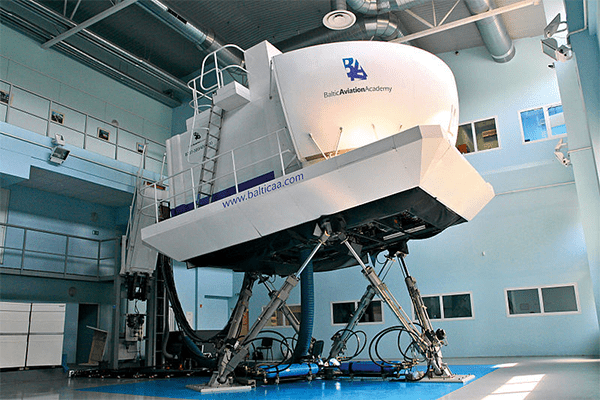
Pilots use simulators, so why not CNC'ers too?
Having a good g-code simulator can save you a ton of time proofing programs. There are basically 5 ways a g-code simulator will help you find problems in your g-code:
1. Backplot: A quick visual indication of what motions the program will make with the cutter. You'd be surprised at how often you'll see some wild move show up on the backplot, even from CAM-generated code. And it just takes a few seconds to run the backplot on your program.
2. Extents and Soft Limits: Checks to make sure the cutter will stay within the area you want it in. This is way slick. If nothing else, it'll help you with your air cutting because the extents tell you the minimum and maximum X, Y, and Z travels for the program. And, soft limits let you generate alarms if the program exceeds the limit. For example, protect your 4th axis by setting an X axis limit that won't let that cutter run into a 4th axis. Or, enter the top of your vise as your Z axis soft limit and check for problems there.
3. Alarm Checks: The backplot might look okay, but your program can still immediately alarm out on the machine. A good simulator will make many of the same tests as your machine controller ahead of time. For example, if the distance from each endpoint to the center of an arc is not the same within a tolerance, you’ll get an alarm.
4. Tooling Summary: A good simulator will compile information about the tools or cutters required by the program. Checking over this list and making sure the right tools are loaded into the machine’s toolchanger is a great test to avoid errors.
5. Subprogram and Macro Tests: A good simulator collects all sorts of information about macros, subprograms, and the variables that are in use. This information can often turn up various problems the part program may encounter.
We've prepared an in-depth article that walks you through how to use a g-code simulator to do these kinds of checks.
Get that article and grab a free 30-day trial of our G-Wizard G-Code Simulator and find out what a good simulator can do for you.
Show Me How G-Wizard Can Help With:


 Up Your Game 4: Faster Part Zero Setup
Every time you run a program on your CNC machine, you have to have some way to ensure that the CNC machine's idea of where the origin of your part is (x=0, y=0, and z=0) matches what's actually needed to properly make the part. For those just starting out, this probably conjures images of edge finders and similar tools. But there are faster and easier ways to setup part zero.
One of my favorites is to designate some part of your workholding solution as part zero so that you can slap a piece of material into it and start your program without further ado. For Example, you might make a corner of the fixed jaw of your machining vise part zero. Then you simply align the workpiece properly with that corner of the jaw and you're ready to go.
Never heard of that approach? Well, I bet you can see how it saves time.
Here are a bunch of other ways of dealing with Part Zero that may save you time.
11 Ways to Locate Part Zero on Your CNC Machine
Up Your Game 5: Faster Fixture Setup with Fixture Plates
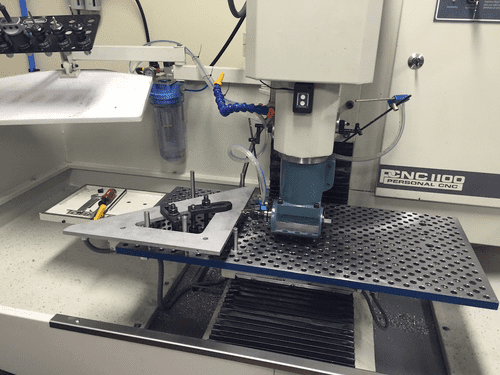
Let's talk about an even more powerful way to save time with setups-use a Fixture Plate instead of the T-Slots on your mill table.
Here's the thing: with T-Slots, there are literally an infinite number of positions on the table. But with a Fixture Plate, there are a fixed number of locations determined by the hole grid.
Here's what's even better, given a fixed number of locations, you can program for them ahead of time. You drop a fixture onto the fixture plate and position it to a pre-determined location. Next you run a short g-code program that knows about that location and automatically sets up your work offsets so that when you run your g-code program, it's all set up and ready to go.
What could be faster and easier for setup? Not much.
Learn all the ins and outs of choosing and using fixture plates from our Complete Guide to Fixture Plates:
Complete Guide to Fixture Plates
Up Your Game 6: Give Up the Vise and Embrace Fixtures
Do you always go to vises as your workholding solution? Maybe you've got some really fancy vises. They make double workstation vises and vises whose jaws are fully machinable. They're awesome workholding solutions, but for many jobs you can do even better.
Time to give up the vise and explore the world of custom fixtures.
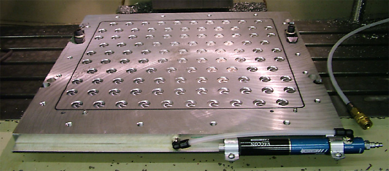
There are many possibilities such as this Plate Fixture:
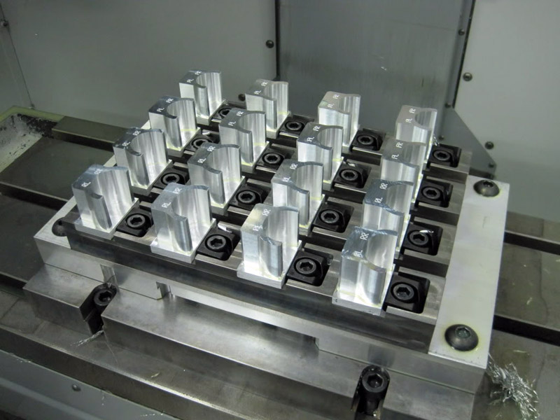
It's goal is to hold as many parts as possible using side clamps. In this case, they're Mitee Bite Clamps, a versatile and popular brand.
Custom Fixtures like the Plate Fixture usually come into play for two reasons. Either because they allow more parts to be machined per setup (and hence the spindle can run longer without attention), or they're used because a part is difficult to hold with more conventional workholding. For example, chucks and collets may make sense to hold round parts.
You'll know when your vise is unable to hold your part very effectively, but when should you choose a custom fixture to hold more parts?
It turns out there's a science to it. You want to create a custom fixture to hold more parts when the time savings involved will more than pay for the extra time spent creating the fixture. If that savings is large enough, you can make a job considerably more profitable. When there isn't enough savings, making a custom fixture kills the profitability of the job and shouldn't be done.
Fortunately we have a couple of resources to help you out here. First, check out our total guide to Workholding on the Mill for a bunch of fixturing ideas:
Total Guide to CNC Jigs, Fixtures, and Workholding
Second, we have a special ROI Calculator that will help you to determine whether it makes sense to create a custom fixture for your job:
Up Your Game 7: Conversational CNC Programming
Does your shop have manual mills and lathes for jobs that are so quick and easy you don't want to use the CNC?
What's the biggest savings you get by using those manual machines?
Some would say you get to use a cheaper spindle for the simple jobs without tying up the much more expensive CNC spindle. That's a good answer, but remember, there are cheap CNC machines available too that could replace your cheap manual machines.
I think for many the real answer is that CADCAM is too cumbersome for simple parts. Suppose you just need a simple bushing for a project? It sure is easy to slap some stock in a 3-jaw chuck on a manual lathe and whip that bushing out in a jiffy.
How about a rectangular bracket with holes in each corner?
Again, it's awfully easy to stick that in the old Bridgeport in the corner and get it done without a lot of CNC muss and fuss. Many experienced machinists will get it done before they could create a CAD drawing of the parts, let alone do the CAM, get it on the CNC machine, and make the part.
So then what's this segment about?
What if there was a way to make your CNC machine just as convenient and powerful for simple parts as a manual machine? What if it was even more powerful and required no CADCAM whatsoever?
The technology to do this is called "Conversational CNC". Basically, you answer a series of simple questions, the Conversational CNC software squirts out a quick g-code program, and you can make the part very very quickly.
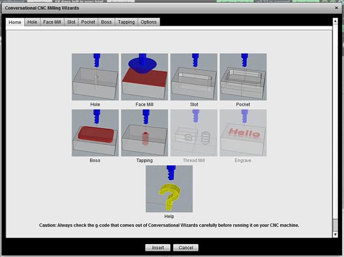
Here's a typical conversational CNC Wizard from our G-Wizard Editor, which includes a free Conversational Programming capability:
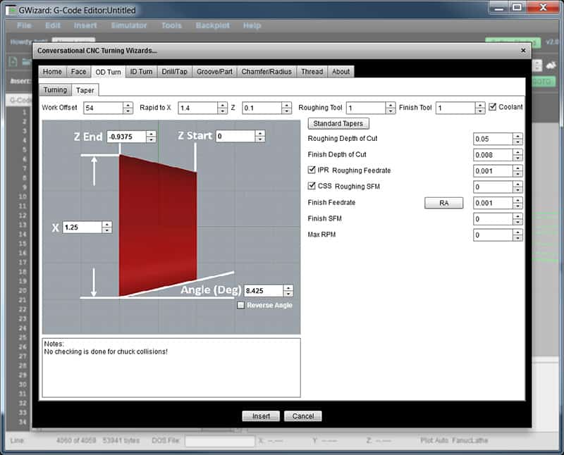
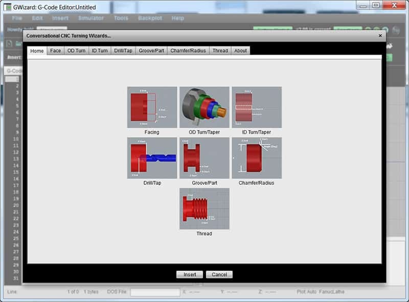
This simple Conversational Programming Wizard is for creating OD Tapers, and as you can see, it is super simple. Just answer a few questions and you get a quick g-code program to cut the taper.
G-Wizard Editor offers a bunch of these for milling machines:
And also for lathes and turning applications:
Using these Wizards you can make simple parts quickly and without needing to crack open complex CADCAM software. Save yourself some time and check them out with a free 30-day trial of our G-Wizard software. Here's more on the Conversational Wizards:
Conversational Programming Wizards
Show Me How G-Wizard Can Help With:
Up Your Game 8: Faster Setup with Pallets
If you've implemented most of the capabilities mentioned so far in your CNC Game, you're doing well. Probably better than most of your peers. So let's keep going!
You must have heard of Pallets, right?
They're the CNC equivalent of interchangeable clips on firearms. They let you load a pallet with raw materials, drop it quickly into your CNC machine, restart, machine parts, and then remove the parts very quickly. They're like trays or fixture plates that are interchangeable and drop into the same repeatable location every time.
Higher end machines, and especially Horizontal Machining Centers may have Pallets built in. They're power operated, swap out in a matter of seconds, and require the spindle to pause only momentarily before it digs into the next pallet to make parts faster than ever.
But did you know you can fit Pallet systems to virtually any milling machine? And, they don't have to be all that expensive either.
Check out this Pierson Pallet System in use by The Blower Shop to make super-chargers for hot rod, marine, and drag racing applications:
The video gives a great idea of how quickly pallets can be changed, and how the parts are changed on the pallets while the CNC machine continues to run on other parts.
The two main things required of a pallet system are:
- Quick changes
- Repeatable installation
Precision down pins or other aids take care of the repeatability. Special ball locks or in the case of Pierson, pneumatic locking systems take care of the quick changes.
You can even create a pallet system by creating small fixture plates that are held in your machining vises.
Up Your Game 9: Vacuum Fixturing
Have you tried vacuum fixturing?
If it'll work for your application, it can be one of the slickest workholding systems imaginable. In fact, for some applications, it's the only way to fly. For example, small thin plates. Say you need to engrave name plates or serial number plates. They're the devil to hold down and keep from flexing but a proper vacuum fixture can make short work of them.
There are some important ins and outs you'll need to know about vacuum fixturing to be successful such as:
- How to generate the vacuum
- How to protect your vacuum pump from coolant
- How to seal leaks to keep your vacuum working at maximum strength
- How to limit the cutting force of your tools so they don't pop the parts up off the vacuum fixture.
You can learn all that and more in our Complete Guide to Vacuum Fixtures:
Complete Guide to Vacuum Fixtures
CNC Routers often work with sheet material for projects like signs that are ideal for vacuum fixturing. See our special CNC Router guide to Vacuum Tables for more:
CNC Router Guide to Vacuum Tables
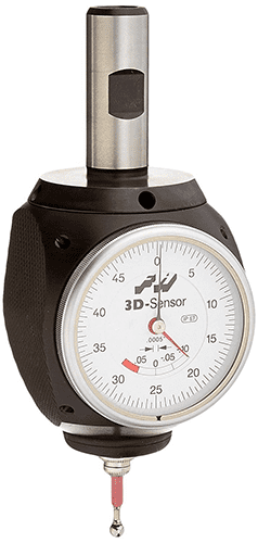
Up Your Game 10: Master Your Digital Probe
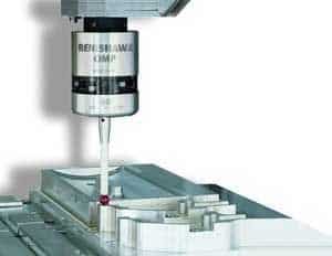
Digital Probes can be the bee's knees for saving you time and even increasing the accuracy of your CNC work.
What's so great about them?
Basically, you can automate measurements and use the results in your g-code programs. Here's a list of some of the more common ways that helps:
- Automatically find and set Part Zero. Program the g-code to locate part zero because you know it's approximate location well enough. For example, suppose you're doing a second op on a part with an existing bore. Have the operator jog so the probe tip is within the bore and then let the g-code do the rest. The probe will precisely locate the bore center and you can use the center or an offset from it as your part zero.
- Automatically adjust a CNC program so it runs square to a part feature. Ever tram a vise so it is square to the machine? You have to sweep the vise jaw with your Dial Test Indicator, then gradually tap the vise until you can sweep the jaw and the DTI needle doesn't move. With a 3D probe, you'd have the probe measure the location of the jaw at either end, calculate the jaw's angle (you want it to be 0 degrees), and then rotate the coordinate system used by the g-code to make the jaw angle zero. That can radically reduce setup time as well as making it possible for a relatively unskilled operator to get things square without having to use a DTI.
- Compensate for temperature changes to make a bore diameter fit tolerances. Expensive CNC machines use glass scales to perform various kinds of compensation. For example, they can compensate for temperature changes that make the dimensions of the machine and parts being machined change. But if you've got a probe, you can do the same thing. Suppose you need a bore that's got to be very accurate. You create a sample bore of the same material and dimensions on your fixture, and make sure it is the right size or at least a known size very close to your desired size. Now, when it's time to machine the new bore, you rough it out but leave a generous finish allowance. Then you use a probe to measure the sample bore. Suppose you're shooting for 2.000" +/- 0.0002" in diameter. The probe measures the sample as 1.998", but it is known to be 2.001". Now you know that thermal or other effects have changed that bore by 0.003". You can inject a scaling factor into the g-code that takes this into account on the finishing pass for your new bore.
- Compensate for Tool Wear. Use a probe to measure a feature when turning and apply a wear offset so the OD comes out within tolerance.
- Inspect and Stop Out of Tolerance Parts. You can use a probe to perform most any inspection you might do on the shop floor. They're not quite as accurate as a full CMM, but they can be close. So you can check key features of parts to be sure they're within tolerance and stop the machine if they're not so an operator can figure out and adjust what's wrong before you make a bunch of scrap parts.
Are you beginning to get the picture? Probes are powerful additions to CNC Machines that can accomplish a lot. But they have to be programmed. You'll need to learn what functions are available for your particular brand of probe and how to invoke them for your g-code programs.
Once you do so, you can begin to pick up these advantages.
Up Your Game 11: Sharpen Your Estimating Game
When we surveyed the CNC Cookbook audience about how the do cost estimates for quoting, we were shocked. We found CNC'ers were more unhappy with their Cost Estimation solutions than they had been with anything else we'd ever surveyed-and by a wide margin. In general, they found that the solutions they were using were very inaccurate, very time consuming, and too expensive.
Ouch! Who can blame them for being unhappy about all that!
Yet Cost Estimation is a critical area of mastery for a successful shop. Bid too low and you're leaving profits on the table, or worse, generating losses. Bid too high and the other guy undercuts you so you don't get the job. The pressure is intense to be right in the sweet spot as CNC Manufacturing is a highly competitive game.
It runs out CNCCookbook can help. We've created G-Wizard Estimator using the same Feeds and Speeds Engine thousands of the world's best manufacturers use on their Shop Floors. What could be more accurate than to use the same numbers as you'll use to manufacture the parts?
Plus, Estimator is super easy to use. Here's a quick video demo:
The demo is part of an in-depth article on how to estimate the part. It shows how easy it is to generate accurate cost estimates using G-Wizard Estimator.
Now here's the best news of all: G-Wizard Estimator is free to G-Wizard Calculator users while it is in Beta Test. That's right. You can be using G-Wizard Estimator absolutely free if you have either a valid free trial or subscription to G-Wizard Calculator.
Check it out:
Get My Free G-Wizard Estimator Trial
You'll need G-Wizard Calculator to use Estimator, so grab a Free 30-Day Trial if you don't already have access:
Get my free 30-day G-Wizard Calculator trial
Up Your Game 12: Make Your 4th Axis Sing
Do you regularly use a 4th axis?
If not, you are probably missing out on the productivity gains they can provide. Forget continuous 4th axis contouring. There are definitely projects that need that capability, but most of the advantages of 4th axis boil down to putting more parts on the table and being able to access more sides of the parts without manual intervention.
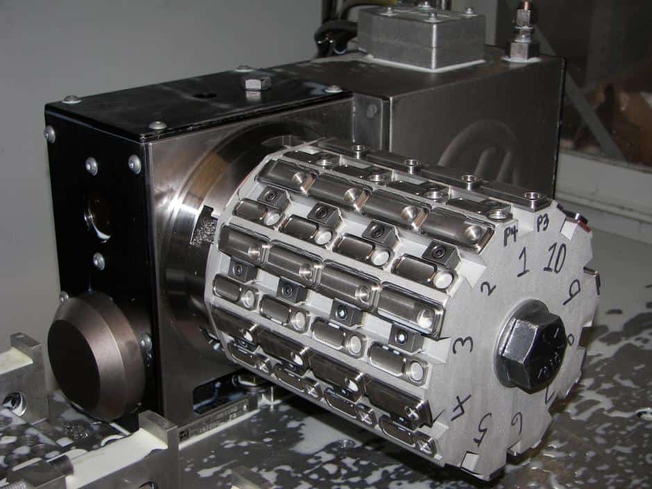
When you use a 4th axis for indexing, programming couldn't be easier. Yes, most CAM packages will handle it. But, you can also just enter the axis moves yourself to rotate the axis to a fixed degree position before you continue machining. So, for example, suppose you've got a fixture that holds 10 strips of small parts on a 4th axis like this:
Each move is 360 degees divided by 10 or 36 degrees. So, start at 0:
A0
A36
<etc.>
See how easy that is?
If the tombstone on your 4th axis is easy enough to change, it can serve as a pallet too.
Check out our article on 4th axis fixturing for more ideas:
14 Great Ideas for 4th Axis Fixturing
Up Your Game 13: Lights Out Machining

Lights Out is scary as heck for many shop owners. Anything could happen, including terrible things we've all seen happen in shops, and there's nobody there to do anything about it. This is a game that's only for very high end shops with bottomless automation budgets, right?
Actually, just a little bit of lights out can be hugely profitable for you if you let it.
For example, that 3D Profiling job that's got tiny stepovers and takes practically forever? Let it run Lights Out. So what if it finishes after 4 hours and the rest of the night is wasted. That's 4 hours your CNC Machine was making money for you and you didn't have to pay an operator. That's what I mean about it being hugely profitable.
Here's the thing. You don't want to be cautious about Lights Out, but there are baby steps you can take along the path and they can make you money right now.
Here's a quick video introduction to Lights Out Manufacturing that I did for Cutting Tool Engineering:
<span data-mce-type="bookmark" style="display: inline-block; width: 0px; overflow: hidden; line-height: 0;" class="mce_SELRES_start"></span>
Here's a trick. If your shop normally has multiple operators during the day, make the Lights Out shift keep one operator. They're just there in case something really terrible happens. Huge peace of mind and way lower overhead. That operator can change an insert, reload parts, or do whatever to keep things humming happily along.
For more on Lights Out, see our Complete Guide:
Definitive Guide to Lights Out Manufacturing
Up Your Game 14: Learn Macro Programming

The reports of my death are greatly exaggerated — Mark Twain.
The death of G-Code programming is also greatly exaggerated!
We're getting near the end of the list, but I've same some real powerhouses for last. Take Macro Programming, for example. Many CNC'ers think they'll never have to deal with g-code because CAM can do it all.
Myth: G-Code Programming is a Thing of the Past
Reality: G-Code Programming Compliments CAM Extremely Well
Like Mark Twain sort of said, “The reports of GCode’s death are greatly exaggerated.” Even MMSOnline agrees that the idea G-Code programming by people instead of CAM software is still relevant.
How can that be true though? After all, modern CAM software is pretty darned wonderful about doing things a manual g-code programmer couldn’t even attempt. Programming a complex 3D surface is trivial with software like MeshCam, but pretty well impossible to do by hand unless the surface can be described by fairly simple mathematical equations. Why would you want to program any g-code by hand?
The answer lies in finding cases that are valuable but not addressed by CAM. These fall into the following general categories:
- Simple parts can be easier with g-code than CAM. You want a rectangular cover plate with 4 holes in it. If you’re proficient with g-code you’re done before you can create a CAD model, run it through CAM, get the gcode onto the machine, and run it. With Conversational CNC, you don’t even have to be proficient at g-code. For all those cases where you thought manual machining was faster, g-code or Conversational CNC will make the CNC machine an even better choice.
- Getting a Second Opinion on Your CAM Code. Even expensive CAM software can have bugs. Or, if they’re not strictly speaking bugs in the CAM, they may be problems with the post-processor. With just a little bit of knowledge about GCode and the help of a GCode Simulator, you can get a second opinion on the CAM-generated GCode and fix minor errors before you have to discover them on the machine.
- Specialized or Downstream Tasks that Complement CAM. As great as they are, CAM programs don’t do everything. There are many specialized tasks that are difficult or impossible to do with CAM. In addition, there are downstream tasks–things that come up when the job is actually on the machine that weren’t contemplated by the CAM or Post. Sometimes these tasks are relegated to GCode because the CAM software won’t do them. Sometimes it’s because the CAM is aiming at a generalized common denominator and something special comes up on the Shop Floor–for example, a slightly different cutting tool has to be used while we wait for another shipment of the normal tools. A simple feeds and speeds change in the gcode will handle it far faster than re-running the CAM, assuming we’re capable of making such simple changes.
It’s this latter category that I want to focus on here by providing an Omnibus List of Applications for GCode Programming alongside CAM. This article talks about 37 very cool things you can do with a little g-code that most CAM software can't do for you:
37 things you can do in g-code that CAM won't help with
Show Me How G-Wizard Can Help With:
Up Your Game 15: Find the Edge of the Envelope

There's a secret that the top most profitable shops use to enhance their competitiveness and profitability. I know because I've talked to several of them and helped them implement that secret. In fact, I know of 2 different examples where the individuals would implement the secret, gain an unfair advantage for their shop, sell the shop for a premium price, and then go on to do it again in a new business.
So what is this secret?
I call it, "pushing the envelope." It requires as little as a week before you can start to take advantage of it.
Most Job Shops have profit margins in the low double digit percents. Let's just say it's 20% for this discussion. That suggests a high degree of competition and that most shops are basically doing the same thing. And it's true-most shops follow conventional wisdom, do things in relatively similar ways, and therefore get similar results.
Now suppose you can improve your cycle times by 20%. That is, your jobs run 20% faster. That savings will almost all go straight into increasing your profits. Or you can use it to lower prices and win more business for growth while still making the same margins.
Now here's the secret part-you can almost beat manufacturer's published feeds and speeds as well as the feeds and speeds produced by calculators like our G-Wizard. The trick is to know by how much and exactly when you can go faster than recommended. Good news: this is something that's relatively easy for you to systematically figure out. And, once you have it figured out, you will have created a significant competitive advantage compared to others who haven't done the same homework.
Here's what you need to do. First, grab a pen and notebook. You need to conduct experiments and record the results to learn. You may also choose to record your results in G-Wizard's Cut Knowledge Base, which was tailor-made for this kind of thing. Now choose a type of feature:
- Pocketing
- 2D Profiling
- Hole Drilling
- etc.
You'll also need to pick your CNC Machine (results will vary from one machine to the next, and even across two of the same model machine, though not by as much as for completely different machines), material you want to work on, and a cutting tool to optimize.
For example, you might have a bunch of Haas VF-2's (or some such) in your shop. And you might be looking to do a lot of high dollar titanium work for aerospace. Pick one of your VF-2's as your guinea pig, lay in a supply of titanium, and pick a cutting tool. Let's say your favorite roughing tool is a 2 flute 3/4" indexable endmill. Now you want to go to school on that cutter, and you want to do it for pocketing.
Using your CAD software, create a test pocket. You want something small enough that it isn't too expensive to test and large enough to be representative. How about something on the order of 4 x 5 inches for your 3/4" indexable tool? And, let's make it 1/2" deep as that's close the limit of what the inserts on our tool can handle anyway.
Now, using G-Wizard's CADCAM Wizards, run them a few times to figure out the highest MRR for this case. They'll give you cut depth and cut width. Be sure to specify HSM roughing if you'll use an HSM toolpath.
That's your starting point.
Your missing is to start cutting pockets, and with each pocket, up the feedrate. I recommend you go in steps of 10-20% until you break or chip an insert. Then back off to the last one that worked, and pick a point halfway between. You might wind up with a series of tests that look a bit like this in your notebook:
Feedrate
Result
Conclusion
0% (G-Wizard's recommended)
Worked Great
Try faster!
+10%
Worked Great
Try faster!
+20%
Chipped Insert
Back off!
+15%
Worked Great
Winner!
By running this series of experiments, you determined that pockets can be run with this tool up to 15% faster than recommended on your Haas VF-2. That's a nice thing to be able to use going forward!
Of course you'll want to do these experiments for most of your commonly used cutters and operations. But having done so, you'll have learned the limitations of your machines and best practices and you'll have pushed the envelop further out.
Very few shops take this step, but it can make a huge difference for you going forward. That notebook you created recording your experiments its now a valuable asset for your shop. Don't let just anyone go through it, and definitely don't let anyone copy it.
Here's another valuable use for your notebook. Once you start pushing the envelope, a lot of cutting edge aerospace practitioners will tell you chatter rapidly becomes the limiting performance factor on higher material removal rates. But chatter, while it is hard to predict absent data, is totally repeatable. There are "chatter zones" that you can map out, and once you know where they are, you can easily avoid them in advance.
Check our article on chatter for more:
Guide to Chatter in Milling and Turning
Conclusion
We've given you 15 ways to up your CNC Game. I'll be surprised if very many of you have already incorporated all of them. But, for those who have, or just those who've discovered more ways to become ever more competitive, let us know how in the comments below.
Be the first to know about updates at CNC Cookbook
Join our newsletter to get updates on what's next at CNC Cookbook.