I recently saw a post come across the Titans of CNC Facebook Group. Someone wanted to know how much to quote an aluminum part. They didn't provide much info except to say it was 1/4" thick, it's a bearing block, and it was to be made of aluminum. Plus, a couple of images of a finished part were provided:
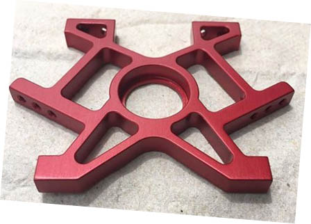
Please provide the text which needs to be rephrased.
Lastly, they only need one part, so there's no point building a bunch of fancy fixtures to mass produce them. In fact, only making one will put tremendous pressure on being able to make one cheaply enough so it's worthwhile.
This is exactly the sort of thing our G-Wizard Estimator software is good for, so I thought it'd make a good example.
CAM Work and Notes on Features
I'll start by working with CAM software to decide on what the features are and to quantify their measurements a bit.
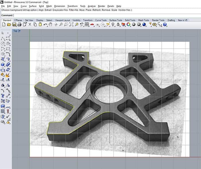
I took the image above and imported it into Photoshop. As you can see, I rotated it so it's at least square along the X and Y axes. It remains titled, and I could've corrected for that too in Photoshop, but I decided it wasn't going to affect the quote all that much.
I then set it up as a background image I could trace in Rhino3D. Most CAD software will let you trace an image.
It's hard to see the tracing, but I traced the left half of the part. Before tracing, I scaled the part so that the thickness corresponded to the 1/4" given by the original poster.
Here's what the trace looks like:
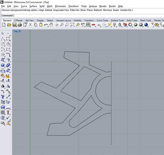
Again, not exactly correct, but close enough. All we're looking to do is latch onto the perimeter lengths of the various shapes in the CAD software.
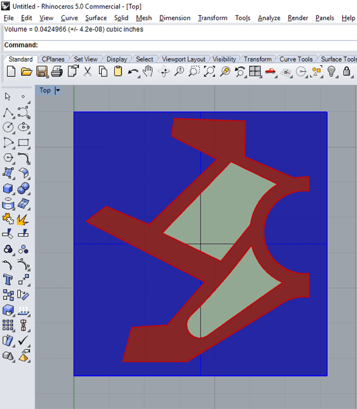
Last CAD step is to estimate the volumes of material to be removed. To do this, I stuck a bounding box around the design, extruded each area as a 3D shape, and then let the CAD tell me the volume of each.
Next question, what sort of workholding will be used?
Without knowing how many parts will be needed, I decided to just use a machining vise. We'll use stock a little thicker than 1/4", and the last step will be to flip the part and face mill off the final skin to bring thickness to 1/4". That allows us to work on all the edges.
I notice there are 4 holes in the top and bottom of each leg from the original photo, so I make the list of features and setups to be machined as follows:
- Surface top and bottom of aluminum with a Face Mill. For the estimate, I'll round this to a 4" x 4" area.
- Outside perimeter. Length is 12.434". Volume to remove is 0.55 cu inches.
- 2 internal pockets. One pocket has a perimeter of 2.226 and the other is 1.951". Volumes are 0.068 and 0.042 cu inches.
- The bearing bore in the middle, which I assume has to be relatively precise. Bearings usually want to be fit to close tolerances. Diameter of the hole is 0.6'ish.
- There is a lip at the bottom that holds the bearing axially, so that's a second bore, call it 0.5'ish diameter. No need for super-precision on that one.
- Drill 4 holes each in top and bottom.
- Drill 6 holes on the angled legs. These holes are at two different angles, so will need to figure out the workholding.
So, in terms of how many times we touch the part it's:
- Drop the raw stock in the vise and machine
- Flip stock upside down and face mill the skin off
- Stand stock up in vise and finish 3 holes on angles. We will use softjaws to sit the piece at the angle required.
- Flip to finish the other 3 holes.
- Stand stock up and do 2 holes in each of the "feet".
- Flip and do 2 more holes in each of the "feet".
Once everything is machined, it's time to run it through a vibratory polisher. The original post says no need to anodize.
It took me about 20 minutes to get this far with my notes for the Quote.
Workholding
What about workholding?
We can use whatever vise solution we like to hold the flat workpiece, but let's pick something that won't mar the aluminum so we don't need to change it on the flip. Let's just use a simple set of aluminum step jaws in a vise and assume we have raw jaws laying around.
For setup, we install the jaws in the vise and mill a clean step.
As the feet are at the correct angle, we can use that same set of jaws in the vise to flip.
Next we need to decide how to hold the workpiece as we drill the holes that are at an angle. This is where we need a little ingenuity to avoid having to make a fancy set of soft jaws or use a 4th axis to position the holes at the right angle.
I want to stand up a pair of 2-4-6 blocks in a milling vise. The part will be clamped between them, perhaps with some coke can aluminum to avoid marring the part.
I'll use a couple of precision pins on either side side of the "vertical" column that's under the holes to support the part so it is level and the holes will be drilled at the right angle. Think of a "T" supported on two pins like this:
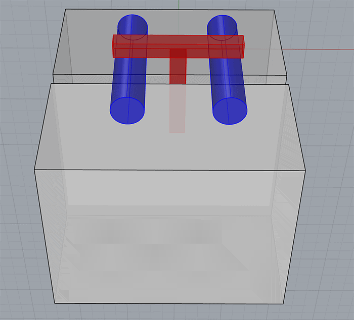
The precision pins could be dowel pins, two identical size twist drills, or whatever you have that is precise enough.
Here's an example of 2-4-6 blocks used in this way:
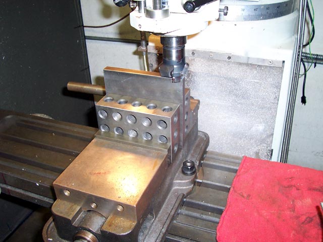
The main trick with this setup is to have enough beef below the pins and below the vise jaws to clamp while the 2-4-6 blocks remain flat. It's worth experimenting a bit with the one good "sample" part if you can to get it right.
Bingo, that'll get us our holes quickly and easily (and therefore cheaply).
It took me another 20 minutes to figure out the workholding. Keep track of time spent quoting. You can't give it away if you want to make money in your shop!
G-Wizard Estimator
We've done the all-important homework to understand what features need to be machined and what sort of workholding solution we'll use.
Now it's time to fire up G-Wizard Estimator and crank through all that. We'll start with estimating the various features I've called out, then make sure we add additional charges for material, CAM Programming, the time we spent quoting, and so on. I've captured all of this on a video so you can see G-Wizard Estimator in action to get a better idea of how it works:
Step-by-step walkthrough of quoting the part with G-WIzard Estimator...
What Could Go Wrong?
Our G-Wizard Estimator Quote should be taken as the absolute best things can go, the cheapest we can make the part, in other words. What if something goes wrong? What about a profit?
Those are two good reasons to add some pad to our quote. The average Job Shops make anywhere from low single digit to low double digit profit margins. That plus mistakes causes me to suggest a minimum pad of 20%. Knowing how much to pad will come from experience, but don't skimp. Start with a bigger pad if you haven't done many jobs. Sure, you'll lose some jobs, but at least you won't lose your shirt.
This is the worst kind of job because you're only making one part. You can't spread the cost of a quote, CAM programming, workholding and all the one-off stuff that hits any job across multiple parts. It all gets charged against that one part. That will make the part seem expensive to your customer, but that's the reality of needing a one-off part.
Conclusion
We've walked through exactly how to go about quoting a simple part using G-Wizard Estimator. Of course you can do quotes with a spreadsheet too. In fact, GW Estimator is basically a tool for creating a spreadsheet.
By building the quote in a spreadsheet you get the total flexibility and customizability of the spreadsheet, but using GW Estimator saves you a huge amount of work creating a custom spreadsheet for each job. It also ensures that your quote is based on the real world feeds and speeds that come from using the same engine as our G-Wizard Feeds and Speeds Calculator.
We surveyed CNC'ers to see how they were going about Cost Estimation and Quoting, and the results were both surprising and scary at the same time.
Here's what's scary:
- Survey respondents were unhappy and looking to switch from ALL of the software solutions they were using. I've never seen a survey come out so uniformly negative.
- The problem with existing solutions is they take a lot of effort to produce quotes and the quotes they produce are very poor quality.
Other than that, Mrs Lincoln, how did you like the play?
I set out to overcome all that with GW Estimator. You can tell from the video how easy it is to use, and that it basically "thinks" about the Estimation and Quoting problem the same way any CNC'er would. That's in contrast to other solutions that can feel very artificial. Sometimes users wonder what they have to do with the real machining processes. Not so when GW Estimator used feature-based estimation (just like your CAM software) that's based off the industry-proven G-Wizard Feeds and Speeds Calculator's underlying engine.
I've saved the best news for last. While G-Wizard Estimator is in Beta, you're welcome to use it completely free. The only catch is you must have either purchased or have a valid free trial of G-Wizard Calculator. Given that you can do everything in Estimator that Calculator does, I'd be giving away my flagship software for free if I didn't have that requirement.
If you've got GW Calculator, here's the G-Wizard Estimator home page:
[ Try G-Wizard Estimator Free ]
If you'd like to try the free trial of GW Calculator (so you can get Estimator), here's how:
[ Try G-Wizard Calculator Free ]
Be the first to know about updates at CNC Cookbook
Join our newsletter to get updates on what's next at CNC Cookbook.