This is my complete guide to 4 Axis CNC Machining.
In this guide you'll learn:
- Why to use a 4th Axis
- How a 4th Axis Works
- 4 Axis CNC Workholding
- 4 Axis for CNC Routers
- DIY 4th Axis
So if you're thinking 4 Axis CNC Machines might be for you, you'll love this guide.
Let's get started.
Chapter 1
Introduction to 4 Axis CNC
Chapter 2
Workholding on 4 Axis CNC Machines

Chapter 3
4 Axis CNC Programming: G-Codes
Chapter 4
How a 4th Axis Works
Chapter 5
4 Axis CNC Router Work
Chapter 6
4th Axis Fixture Ideas
Chapter 7
DIY 4th Axis Design Notes
CHAPTER 1:
Introduction to 4 Axis CNC
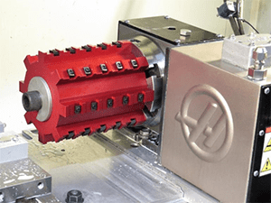
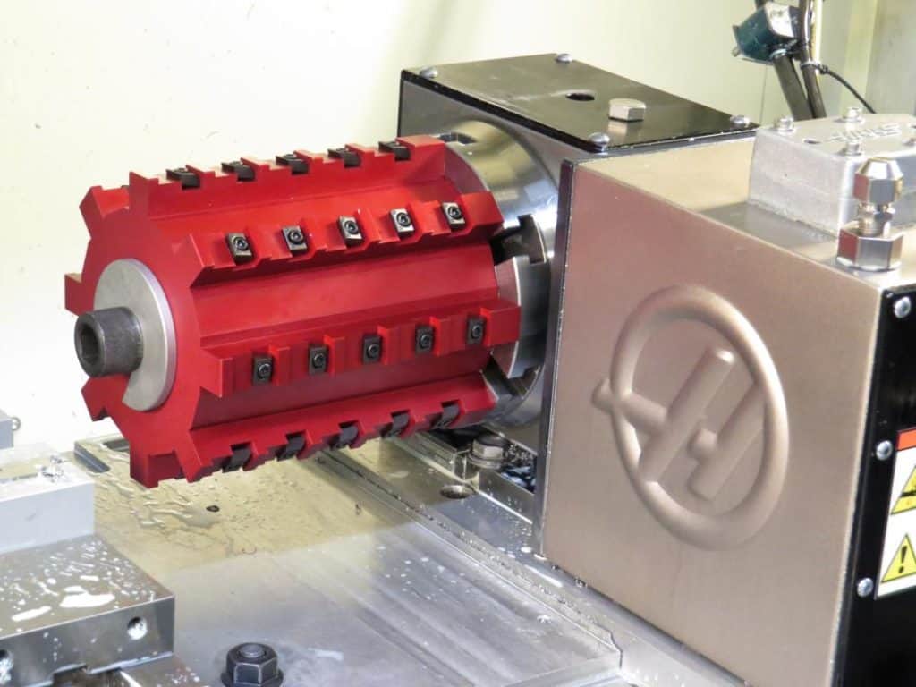
4th Axis machining is an interesting and important sub-part of the CNC milling world. Haas actually got it’s start building a 4th axis before it ever built entire CNC machines (pictured on the right). This is an article series to help beginners understand how and why a 4th Axis is used on CNC Mills. In the first installment, we’ll look at what a 4th axis is used for. In the second, we’ll look at how they work.
If you’re new to CNC, your first impression may be that the 4th axis is used in the same way a rotary table is used for manual machining. Indeed, there are many projects out there where someone converted a manual rotab to become a 4th axis. While there is a grain of truth to this idea, largely it’s incorrect.
First, a 4th axis machine can move in linear directions such as X axis, Y axis, and Z axis. But it also has a rotary axis, usually designated as the A axis or B axis.
Most manual machining 4th axis work is about cutting features along an arc, something that’s hard to do with a manual machine. With CNC, cutting along an arc is easy–that’s what the G02 and G03 g-codes are for. There are cases where we do continuous machining with a 4th axis–in other words, we want the cutter to be machining as the 4th axis turns. But there are also many other applications.
For example, we might employ 4 axis CNC to machine angled features. These are features that are not perpendicular to one of the part's faces. A 4th axis is really the only efficient way to machine angled features.
Let’s go over three major categories.

4th Axis Indexing for Access
First thing to talk about is this term “indexing”. A 4th axis is typically either used in an “indexing” mode or a “continuous” mode. When indexing, no cutting happens until the 4th axis is stopped (and often locked with a brake of some kind). In fact, there are some types which are called “indexers” that can only be used to index in fixed degree increments rather than continuously rotating to any desired position. By contrast, “continuous” means that machining happens as the part is being rotated. For example, to produce a cam lobe.
You may wonder why you’d ever want anything but continuous machining, but bear with me–there are lots of useful ways to take advantage of indexing. Also, you’ll need much fancier CAM software to program continous machining. It’s very powerful, but plenty of work (perhaps even the majority of 4th axis work) is done simply with indexing.
The most obvious case for indexing is to gain better access to the part. Suppose you’re making something complex, like a gear:
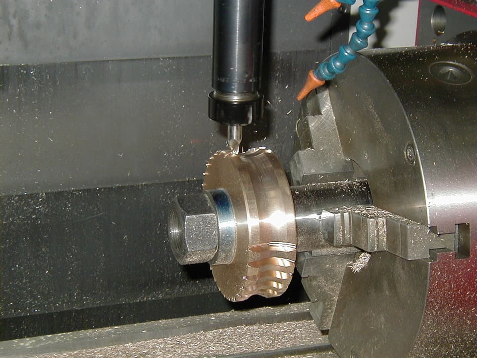
Machining a gear with a 4th axis…
The 4th Axis indexes each tooth into position, stops, and then the cutter makes a pass back and forth until the tooth is done. Then the next tooth is indexed into position.
Gears are kind of an extreme case because it would be hard to imagine how to make one if we couldn’t index the teeth. But, there are much simpler cases where indexing is also extremely helpful.
Suppose you have a part like a throttle body that has holes on all sides. You could build fixtures and do a bunch of setups, one for each side. Or, you could also use a 4th axis to index the sides so more than one can be machined with a single setup.
BTW, a 4th Axis is usually the best way to provide access to angled features. Not every feature is perpendicular to one of the faces of the part. Sometimes we must machine angled features.
In a future article, we’ll get into programming 4th axis indexing.
4th Axis Indexing for More Parts
They say that Horizontal Machining Centers can be tremendously more productive than Vertical Machining Centers. One reason is that the chips are easier to keep clear on a Horizontal since gravity is helping rather than forcing them further down into the hole where they’re harder to get at. But another reason is that almost any Horizontal Mill has a 4th Axis Tombstone arrangement:
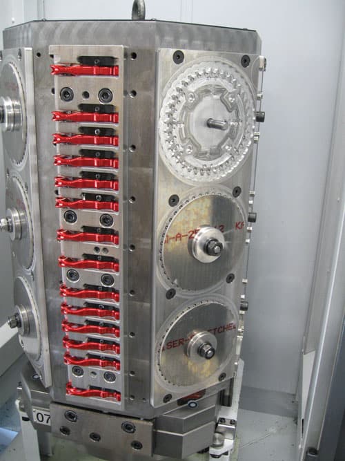
A 4th Axis Tombstone on a Horizontal Mill…
Pictured is a great example from our article on a successful manufacturer that is so productive with their Horizontal Mills they only need 2 1/2 machinists–it’s a family business. They load and unload the tombstone (which is the big upright chunk of cast iron the parts are held to while machining) while the machine is busy cutting new parts on a tombstone in the machine. As you can see, they have things set up so they can even do more than one kind of part on a tombstone. This is a powerful technique for improving shop productivity, but it’s not strictly limited to Horizontal Mills.
You can stick a tombstone arrangement on a vertical mill too, there’s just less clearance available so you’ll want relatively “flat” parts to use one:
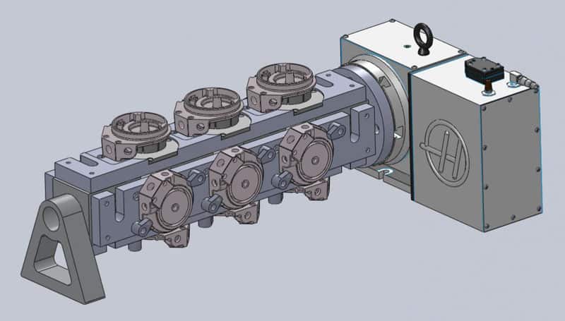
Now I’ll bet you’re wondering how useful that 4th axis with tombstone is on VMC?
Well, I wrote a whole article about how to figure it out, but here is the bottom line:
In the examples considered in the article, the 4th axis with tombstone increased your available surface area for parts as much as 116%! Now tell me, would having room for nearly twice the parts on your table increase productivity? For many jobs it sure would.
4th Axis Continuous Machining
Now comes the fancy stuff: 4th Axis Continuous Machining, which may also be referred to as “4th Axis Contouring”. This video of a turbine blade being machined makes the difference between continuous machining and indexing pretty obvious:
There are a couple of advantages to Continuous Machining. First, you can machine shapes that would otherwise be impossible or very difficult. The closest thing possible without continuous machining would be to index as many positions as possible and use 3D contouring toolpaths to try to get the job done. This can be surprisingly effective, but is seldom as powerful as true Continuous Machining.
The second advantage comes when profiling with a ballnose cutter. The ballnose has a weakness, which is that the closer you get to the tip, the slower the flutes are spinning. It sounds counter-intuitive, but just think of that tip as a series of concentric circles at different heights. The ones near the tip are smaller circles, their circumference is shorter, yet they’re spinning at exactly the same rpm as the bigger circles up higher. Hence, the tip moves slower. Conceptually, the exact tip isn’t really moving at all as it is a circle with zero radius.
This observation leads to a clever technique called “Sturz Milling”. With this technique, you use the 4th axis to allow the ballnose to be presented to the workpiece at an angle, so the side of the ball is used more than the tip:
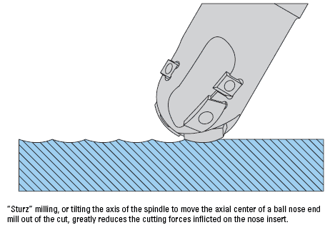
Not only does this allow faster milling (higher feedrates are possible) but it gives a better surface finish and even improves tool life.
4th Axis “Wrap” Machining or “Wrapping”
I’d be remiss if I didn’t mention the special case of 4th Axis Continous Machining which is called wrapping. Imagine you want to engrave some text on the side of a cylinder. You could lay out a 2 1/2D engraving on a flat surface, and then if you had some way to “wrap” that engraving around the cylinder, it would come out right. It turns out there are ways to do this ranging from software utilities to options in your CAM software, to even the expedient of plugging the Y-axis into your 4th axis and letting the hardware think it’s machining on a flat surface when in fact its doing wrapping on a cylinder.
Conclusion
A 4th Axis can be a powerful addition to your CNC arsenal. It enables all new kinds of machining and can also make existing jobs run faster and require less setup.
CHAPTER 2:
4 Axis CNC Workholding
It should come as no surprise that 4th Axis workholding is pretty similar to workholding on a plain old mill table. Heck, many Horizontal Mills don’t have anything but a palletized 4th Axis Tombstone as their “table”.
So, we’ll work through the workholding options and they’ll seem pretty familiar.
4th Axis Tombstones = Mill Table Fixture Plates
Tombstones correspond to Fixture Plates on a mill. There are many different shapes and sizes of Tombstones available for 4th Axes. Here’s one I’ve shown before from a big horizontal milling setup:

A 4th Axis Tombstone on a Horizontal Mill…
The vertical mill version is similar, but typically a bit smaller:

Tombstone on a vertical mill…
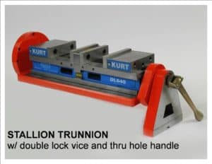
The goals with Tombstones are usually to get access to more parts, more sides, and to make swapping many parts into and out of the machine go fast. You’re typically putting parts on or off the fixture plates while the machine is running and as soon as it stops, you swap either the fixture plates or the whole tombstone to get the machine running again quickly. Depending on the size of the part, you made need an offset arrangement more like the Stallion version pictured above.
How do Tombstones Increase Work Area on CNC Machines with a 4th Axis?
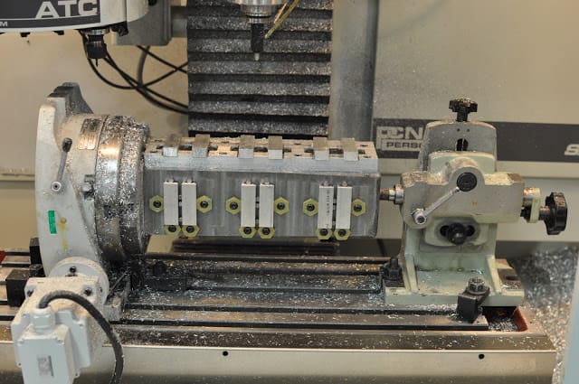
A tombstone with fixtures on all four sides set up on a Tormach CNC Mill…
I was reading an article about Tombstones in the Tormach blog recently and it got me to thinking about how Tombstones on VMC’s can make a job more profitable.
Tombstones are par for the course on Horizontal Machine Centers, but they’re seen a lot less often on Vertical Machining Centers. Perhaps it’s because they’re just built into a lot of HMC’s at the factory whereas you have to set one up using a 4th Axis on the a VMC. The question for this article is how to get a handle on their value?
There’s an old saying that you’re not getting the most return out of your CNC Machine until you have fixtured a job up so that every square inch of the table’s accessible area is being used to make parts. Put as many parts as possible down for each setup, in other words. Relying on just a single machining vise, for example, can mean a lot of available table area is wasted versus putting two vises on the table (so you get 2 parts per setup), or two double station vises (so you get 4 parts per setup). It’s all about how many parts the machine can “chew” on for each setup. The more the merrier because your setup time divided among all the parts will invariably be less on a per part basis.
With that in mind, why not think of that Tombstone in the 4th Axis as being all about creating more addressable table surface area?
On a Tormach PCNC 1100, you get 18 inches of X and 9.5 inches of Y travel. So, that’s 171 square inches you can utilize for making parts–fit as many in as you can!
Now consider a tombstone like the one pictured above. It’s like having 4 smaller tables available. In fact the width of the tombstone is 4″and the length is 13″, so counting all 4 sides, you get 4 x 4 x 13 = 208 square inches. That’s actually 22% more area than the travels suggest would be available on the table. So, for about every 4 parts we can fit 1 part gets a free ride. That’s not bad!
In addition, we can machine 3 faces on each part. Ordinarily, that would take 3 setups which would be a lot more time consuming. Pretty cool, eh? Depending on how much additional setup time is required for this arrangement versus just using the table, we’ve probably made our job more profitable. Perhaps by quite a bit.
Can we do better than that?
Suppose we had a tombstone that was a full 18″ long to match the Tormach’s travel. Yes, we might need a big fixture plate so the 4th axis and tailstock have room on the table, but that’s doable. With the same math, we’d get 4″ x 18″ x 4 sides = 288 square inches. Dang, now we’ve got 68% more available area and we’re really starting to cook with fire. 68% more parts each time we press the green button get finished.
Suppose we create our own “Tombstone” with a piece of 1″ thick cast iron. We can go 2″ if we want it to be more rigid. Now, let’s further assume it is the width of the table’s diameter, which for the 8″ 4th axis is 7.9″. We’ll mount it dead center of the axis, make it a full 18″ long, and use the two sides. Our total area is now 7.9 inches x 18 inches x 2 sides = 284 square inches. That’s almost as good as the earlier tombstone example, and gives us 66% more area.
What if we have a triangular tombstone that just fits in the inscribed circle of the table? No problem. The math says each of the 3 faces of the triangular tombstone will be 6.84 inches, so we have 6.84 x 18 x 3 = 369 sq inches. That’s 116% more area than on our table–twice as many parts per run. Winner, winner, chicken dinner!
When you look at it this way, it’s not hard to see how a 4th axis with tombstone can increase the available area for parts in each setup and make available more faces of the part to be machined.
4th Axis + Lathe Chucks
For round parts, and for many things that go ’round, lathe tooling is where its at. After all, it’s optimized to do workholding along a rotating axis. Hence, it’s very common to mount lathe chucks on your 4th Axis:

Machining a gear with a 4th axis…
All the same ideas that apply to which chuck to use in a lathe work for 4th Axes on mills. Years ago, I put together a chart that has been useful to me in turning work and we can refer to it here too:
Method
Precision
Repeatability
Convenience
Notes
3-Jaw Self-Centering Chuck
Low
Low
High
Common, cheap, simple. Low precision, low repeatability if you remove the workpiece and have to put it back.
4-Jaw Chuck
High
High
Medium
Can be time consuming to individually adjust the jaws, but will result in high precision. Can hold pieces offset for turning cams or eccentrics. Can hold irregular shapes and square or rectangular stock.
6-Jaw Self-Centering Chuck
Medium
Medium
High
Best for thin wall work or to grip finished edges of workpiece. Obviously good for hex stock.
Faceplate Turning
Varies w/ Setup
Medium
Low
Great for irregular shapes. Involves clamps like a milling setup. May need counterweights to keep things balanced.
Turning Between Centers
High
High
Low
Great precision, allows part to be put back between centers with very high repeatability.
Constant Face Turning
High
High
High
The modern alternative to turning between centers. Instead of using lathe dogs, which are kind of a nuisance to set up, the constant face system uses hydraulic or other force to grip and drive the spindle end. You can now buy these systems relatively cheaply on eBay (see seller 800Watt who sold me mine).
Collet Chuck
High
High
High
Fast, high precision, high repeatability, grips well, unlikely to mar workpiece, grip spread over a wide area. Expensive chucks and collets. Handles limited lengths. Workpiece must be round and must fit nearly exactly to the collet size.
Expanding Arbors
High
High
High
These work from the inside out rather than the outside in but are otherwise much like collets.
“Repeatability” applies to the ease with which you can remove a part and put it right back into the chuck in exactly the same position so you can continue machining. It’s a big factor to consider, but typically isn’t as important for 4th Axis work as it is for turning. When turning, for example, you often have to swap a part end for end, or you may have to take an existing part and put it in the lathe to rework some aspect. With a 4th Axis, you will often just stick in a piece of raw material, in which case Repeatability is not a factor. Hence the ubiquity of the relatively non-repeatable 3-jaw chuck for 4th Axis work.
Turning between centers happens fairly often with a 4th Axis just because you have to make sure you’re supporting any part with significant overhang out at the end too. How much is significant? I was taught 3 or 4 diameters was about a much as you want to hang off the chuck on a lathe before you start looking for more support.
Collets are really nice for turning work (hence the ubiquity of the old Hardinge Lathes and their 5C collet system). They get high marks on just about every aspect. It’s no coincidence that the original Haas 4th Axis had a 5C indexer:

Original Haas 4th Axis incorporated a 5C Collet Indexer…
Perhaps the biggest shortcoming of 5C collets is they only allow for parts of relatively limited diameter. This can be overcome by turning things on their head. Consider this setup:
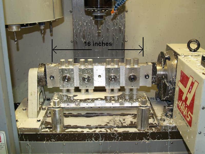
I never would have guessed it, but Geof on CNCZone says the following 4-axis mill set up was able to machine these aluminum bars to length, ensure the faces were square, and drill and tap a hole faster than he could do it in a lathe. You can imagine each of those 4 parts being a 5C spin indexer and suddenly you fit quite a few more parts on your 4th Axis.
4th Axis Vise
How about the ability to stick a normal milling vise into a 4th Axis? Stallion makes one such:
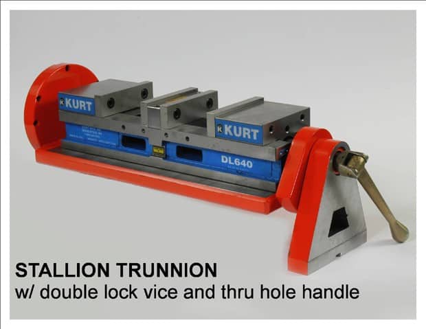
In fact, the Stallion is a bit more versatile because it isn’t just for vises–it’s basically a fixturing system:
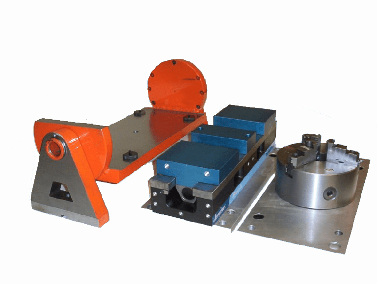
I’ve written at more length on Stallion’s Trunnion fixtures in another post. They’re very slick, but you need to make sure they solve the problem you need solved for your 4th Axis. In particular, the access to the part is going to be limited to the access you can get form a vise. As such, you’d be looking to use a Vise on your 4th Axis largely because it is super easy, familiar, and to gain access to 3 sides of the work rather than just the top in a single setup.
Note that on a big Horizontal Mill tombstone, you may mount multiple vises on 4 sides of the tombstone and even more than one on each side. That creates a lot of capacity!
Conclusion
Workholding and Fixturing are always an art that it pays to learn well. I’m always on the lookup for clever setups and fixtures and you should be too. The 4th Axis opens whole new avenues for fixturing and setup.
CHAPTER 3:
4 Axis Programming: G-Codes
The G-Codes needed to program 4th Axis motion are pretty simple, and logically follow the g-codes needed for 3 Axis CNC Motion.

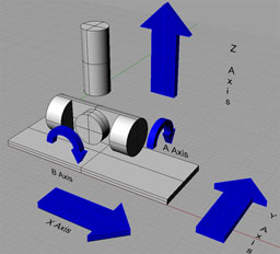
Let's start with an axis diagram that makes it easier to see what's going on with the CNC Machines Axes:
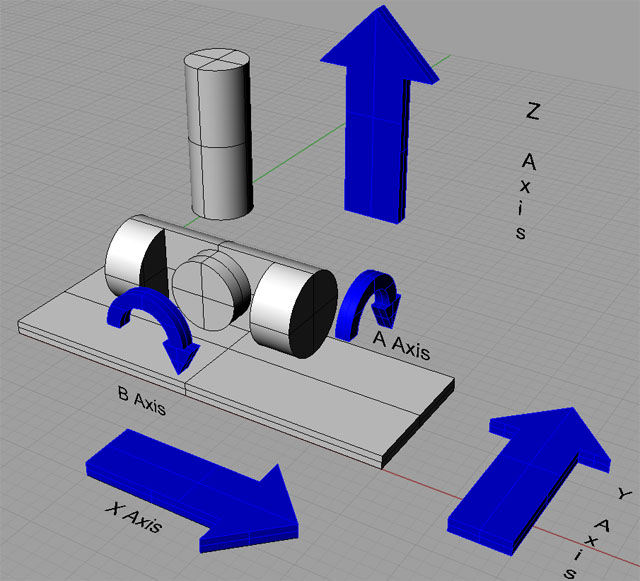
The first 3 Axes are the familiar X axis, Y axis, and Z axis. The A axis and B axis are potential 4th Axes. We refer to the A axis and B axis as "rotary axis". If the machine has both A axis and B axis and they are independent, it is a 5 Axis CNC Machine.
In other words, you can choose to install your 4th Axis as either Axis A or Axis B. The convention is that A has a rotary axis that spins about the machine's X axis and B spins about the machine's Y axis. In practice, since the 4th Axis is usually removable, most of the time you'll refer to it as the A-Axis whether it is aligned with respect to X or Y. Aligning to X or Y is just a decision you'll make based on the job you're doing.
Let's assume you choose to set your 4th Axis up as "A". Then you can simply refer to it as such in G-Code. So, for example, you can rotate to the 0 position via "A0".
What About Units?
X axis, Y axis, and Z axis moves are expressed in inches or mm depending on which unit system is in effect.
For a rotary axis (which you’ll only be using on a 4 or 5 axis machine), we don’t use dimensions for the units, we use angles, typically in degrees. Rotating the 4th A axis to the 90 degree position might be done as A90, for example.
Incremental vs Absolute and Offsets
With most controls, 4th Axis coordinates get all the tricks regular coordinates have available. So, for example, you can use Absolute or Incremental Coordinates.
Work Offsets will contain not just an XYZ but also the 4th Axis coordinate. You can imagine if you've got a tombstone with parts on 4 sides, you might want 4 Work Offsets set up to correspond to each of the 4 sides of your tombstone. And, if there are 4 parts on each side, you might also have 4 sides times 4 parts or 16 work offsets.
With those 16 work offsets, you can create 1 part program in your CAM software, set it up as a subprogram, then set the work coordinate, call the part subprogram, set the next work coordinate, call the subprogram, and so on, to make all 16 parts.
Part Zero in 4 Axis CNC Machining
Part Zero is, of course, the origin, when programming your part. It's 0, 0, 0 when you drew the part in your CAD program or set up the origin in your CAM software.
When 4th Axis programming, it is often convenient to have a part 0 on each indexed face of a tombstone, for example. That way you can use Work Offsets as described above.
That makes sense for 4 axis CNC indexing. But, when doing continuous 4th axis machining, it might make more sense to have the axis the 4th spins on be 0.
Choosing part zero for continuous machining will require that you be very familiar with your CAM software.
Programming for Continuous 4th Axis Work
The brings me to a discussion of programming for continuous 4th axis work.
That's the most complex kind of 4 Axis CNC Machining. It's not something you will typically do by hand coding g-code. Instead, you will use one of 2 kinds of software to help.
4 Axis Wrapper Software
4 Axis Wrapper Software is the simplest way to do a little 4 Axis CNC Programming for continous work. In essence, you program the work on a flat XYZ plane. For example, you might create some sort of text engraving. The 4 Axis Wrapper Software will then transform that g-code so it is wrapped around a cylinder of a particular diameter.
Fusion 360, a popular CAM package, can do 4th Axis Wrapping.
4 Axis CAM Software
Wrapper Software can be useful, but clearly it has many limitations. To do true 4 Axis Continous Contouring requires 4 Axis-capable CAM Software.
Fusion 360 does not only wrapping, but continuous 4 Axis CNC Machining. Here's a quick video showing Fusion 360's 4 Axis Features:
CHAPTER 4:
How a 4th Axis Works
In this chapter, I want to talk a little bit about the mechanics of how a 4th Axis works and what’s inside one. We have a lot of readers who are interested in the details and even in building their own 4th axis.
To create a 4th Axis basically requires that the axis be well mounted so it can spin, and that there be some means of controlling that spin via g-code program, preferably with as little backlash as possible–backlash is the enemy of CNC. The mounting process is not unlike mounting a spindle. Typically there will be a shaft between bearings. I suppose you could even contemplate sleeve bearings as opposed to high precision angular contact bearings, although the latter are standard industry practice. Tapered roller bearings can also work reasonably well for a 4th axis. There are some cases I’ll get to where the 4th Axis is analagous to a lathe headstock, so that’s another way to think about it.
Let’s dig into some of design issues and mechanism types for a 4th Axis:

Geneva Mechanisms and Other Indexers
Perhaps the simplest low backlash approach would be a Geneva Mechanism. They’re simple, reliable, and reasonably precise. The drawback is that 4th Axis Continuous machining is impossible because the Geneva Mechanism has a fixed set of stopping places. Hence can only be used as a pure indexer and not a true 4th Axis.
Here is a shopmade air cylinder driven indexer that’s pretty neat:
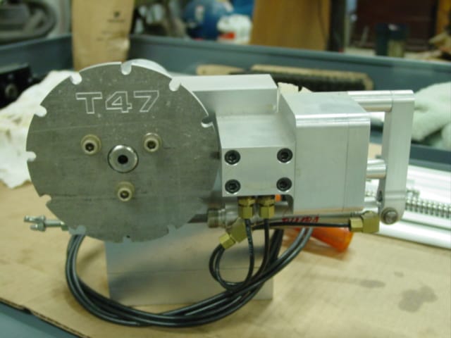
A shopmade air-cylinder indexer…
Perhaps the most sophisticated indexing-only mechanism would be Face or Hirth Gears.
Rotary Table Worm Gear
Hobbyists are often taken with the idea of using a Rotary Table. They’re cheap, readily available (perhaps you have one left over from your manual machining days), already set up for workholding, and it’s pretty easy to stick a stepper motor on one and start using it as a 4th axis. There’s just one little problem, only it isn’t so little: backlash.
The worm gear mechanism of most rotary tables has a fair amount of backlash. They’re set up so you can adjust it out, but doing so makes the table prone to binding and wears out the bronze gears fairly quickly. They require adjustment often to keep the backlash out. Still, they’re not a bad way to get started with 4th axis machining, especially if you’re only planning on occasional low intensity use.
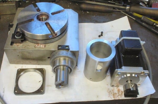
It’s not hard to convert a rotary table to a 4th axis, but they have a lot of backlash and will wear out fairly quickly…
Timing Belts
You could use a timing belt just like the kind that are used for the X, Y, and Z axes on a mill. The problem is you’d really like to gear things down more than the timing belt allows. Even a linear axis has the further reduction of the leadscrew. This approach is doable, but you need to pay close attention to the resolution of your stepper or servo motor lest you wind up with not enough accuracy positioning the axis. Again, you’re not going to be able to gear it down very much.
Because of this, I find servos seem to work better in design sketches I’ve done around 4th Axis timing belt drives simply because they have way more resolution than the number of steps per revolution of a typical stepper motor. There are other advantages too.
If you’d like to do some back of the envelope calculations for this style, I’ve got a spreadsheet for you to download that does that. One neat thing about this style is it allows fairly high speed operation of the 4th axis spindle. Enough so that with the proper timing belt ratios you could use it as a lathe headstock and attach the tooling to your mill spindle. Pretty soon you’ve got a simple mill-turn setup that’s pretty potent:
See my write up on this neat combination 4th Axis and Mill-Turning gizmo…
Harmonic Drive
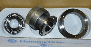
The next step up is a gizmo called a “Harmonic Drive”. I won’t try to explain how Harmonic Drives work, there is always Wikipedia for that. Suffice it to say they offer nearly backlash-free gear reduction–perfect for this application. Put one between your servo or stepper motor and the 4th Axis spindle and you’re done.
I got one off eBay relatively cheaply:
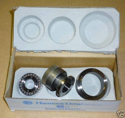
Harmonic Drive…
For a long time they were really cheap on eBay as they were Industrial Surplus and nobody knew what they were good for. Unfortunately, the word is out so you have to look carefully to find a deal. Nevertheless, one with an appropriate ratio would make a sweet 4th Axis. You could either gut and remachine a rotary table or remachine a less expensive 5C Collet Indexer and you’ve have a real slick 4th Axis when you were done.
Globoidal Cam
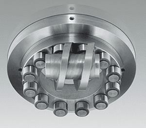
There are many more odd mechanisms that eliminate backlash and perform the reduction function. I wanted to mention one more since Haas just launched a new high-speed 4th Axis that uses this approach. It’s called a “Globoidal Cam”. Here’s a couple styles of what they look like:
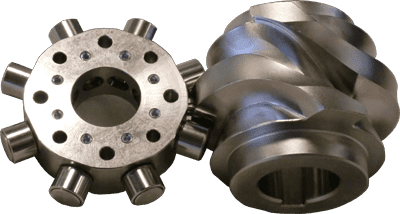
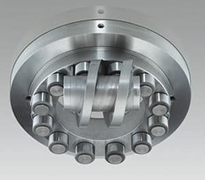
The “pins” are bearings so the motion is very low friction and precise. There’s a pin on either side of the “worm cam” (my made up term) and the thing is made with enough precision that there’s no backlash or freeplay available to the pins. They hold that cam pretty tightly on both sides. It would be interesting to try to machine a Globoidal Cam with enough precision to work in such an application.
Brakes
Enough about the rotary motion, we also want to be able to stop our 4th Axis. In addition, we want significant holding force when stopped. If we’re using the 4th as an Indexing tool, and stopping to machine, note that the further off-axis the part is, the more leverage it has to try to turn the axis. If you’re face milling or something equally aggressive, you may be very glad you’ve got a brake of some kind to lock the axis. Here’s an air-activated disk brake on a shopmade 4th Axis:
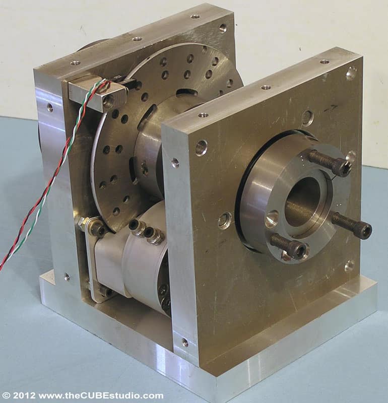
A 4th Axis Lathe?
One of the things I didn’t mention in the prior article on what a 4th Axis is used for is the possibility of using one to turn your mill into a lathe. If you’ve got CNC lathes, there’s probably little point in doing so. But if all you’ve got is a mill, and indeed, for certain operations even if you have a lathe, it can save you a lot of time and effort to be able to turn parts on your mill.
Traditionally, this can be done either by chucking up the part in the mill spindle and putting the lathe tooling on the table, or by sticking a lathe headstock on the mill table and mounting the turning tools on the spindle. Both methods work, but with a 4th Axis that is capable of spinning fast enough to act as a lathe headstock as well as capable of indexing as a 4th Axis, there are a world of possibilities. I’m not going to delve into them too deeply here, but check out some of my posts about CUBEstudio’s 4th Axis that can Mill Turn for more.
CHAPTER 5:
4 Axis CNC Router
For the most part, the principals of 4th Axis use with a CNC Router on wood are much the same as the more metal-focused articles that have come before. We'll focus on how it all looks on a CNC Router as well as common applications for the 4th Axis on a CNC Router.

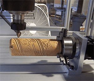
You can mount a typical 4th axis on a router table and go to town:
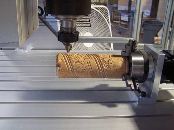
The goal of 4th axis woodworking is typically engraving or columns…
The goals of 4th Axis woodworking are often a little different. You seldom see 4th axis as a way to access more sides of the part without more setups or as a way to machine more parts in one setup through indexing. CNC Routers already have lots of XY area and don't need a 4th axis to create more area. In fact their limited Z clearance would make it hard to use one for the purpose anyway.
Most 4th Axis woodworking is about continuous indexing in order to do round work such as engraved cylinders of columns of various kinds for architectural work:
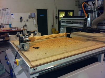
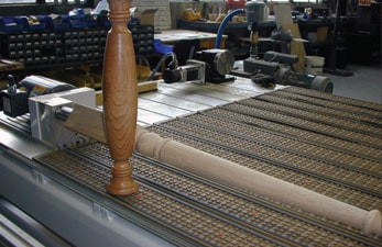
This sort of thing is ornamental turning work, and in fact, it is common to refer to the 4th Axis as a “Lathe Attachment” in the CNC Router world. Here’s a video showing one of my favorite style lathe attachments which involves mounting the 4th axis permanently alongside the table:
A 4th Axis installed on a CNC Router...
The video shows a lot of the typical pineapple and other shapes common to ornamental turning. Slinging the workpiece alongside the table allows for quite large work to be done and gets away from the Z-travel limitation that many router tables have.
CNCZone has some neat pictures of a DIY lathe attachment for a CNC Router:
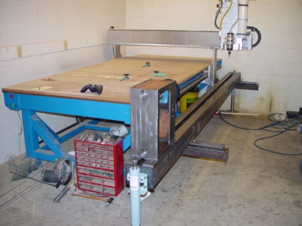
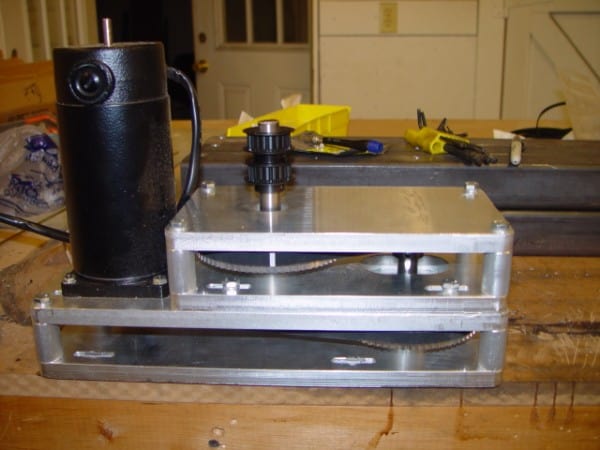
His solution for low backlash gear reduction was to build a “gearbox” using timing pulleys. Clever!
Here’s a video of some 4th axis work on a CNC Router to create a gunstock. Very cool work:
Some great how-to tips in this video of making a gunstock with a 4th axis…
For more on 4axis cnc router work, see our dedicated article.
CHAPTER 6:
4th Axis Fixture Ideas
Here's a compendium of ideas for 4th axis fixturing that will save time and help make your jobs more profitable.

Quickie: A lot of 4th Axis and Indexers have an MT taper hole in the center. Purchase a few MT toolholders and you've got quick change holders for small parts on your 4th axis!
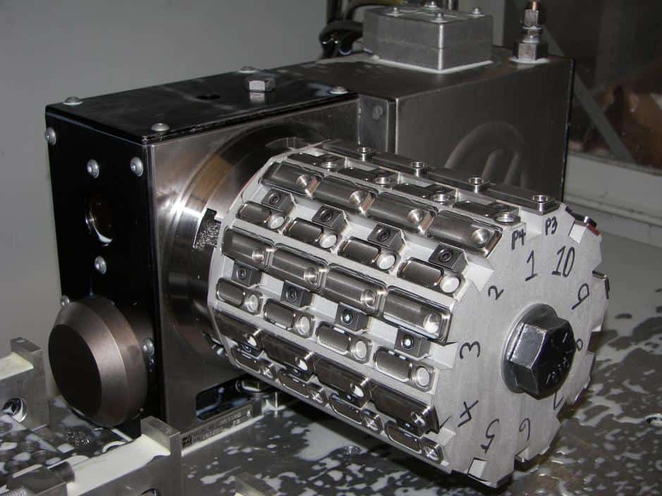
A quick way to access a lot of small parts with a Fourth Axis. The cylinders can be swapped out quickly for almost palette-changer like setup times.
Another cylindrical fixture for small parts. Note the washer cutout. Loosen the bolt 1/4 turn, slide the washer off, and the center hole allows the fixture to be removed and swapped for another quickly.
Lots of small parts in a fourth axis fixture with pneumatic clamping…
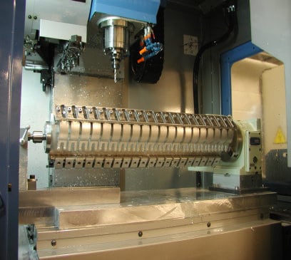
Another setup for making lots of small parts. It overhangs the 4th and the tailstock so the tombstone can use the full travels of the machine for maximum production…
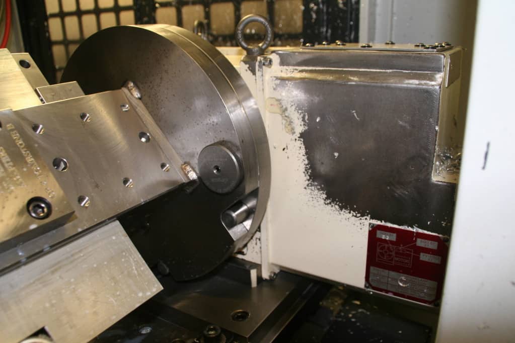
Depending on your application, it makes sense to think about how to make setup faster. Dialing in the fourth axis and tailstock can be a pain, but if you have a fixture plate, you can set up for drop in repeatability. Next question is how to repeat installing you fixtures on the fourth axis? This picture shows one of two Jergens Ball Locks that are used together with two 3/4″ dowel pins (one right below that ball lock in the pic) to provide the fixture plate equivalent of drop in repeatable setups on the fourth axis.
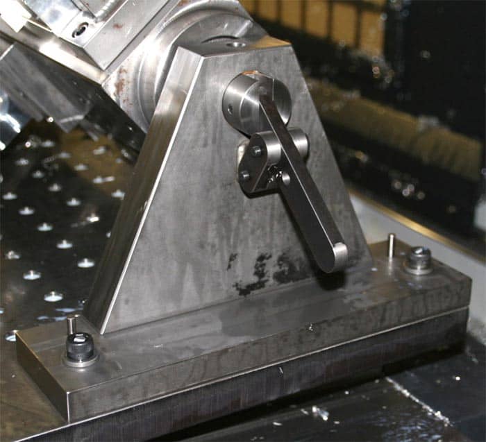
This shop-made fourth axis tailstock that goes with the same Jergens locked tombstone above has some cool ideas. There’s a pin operated by the lever that engages an angular contact bearing in the tombstone.
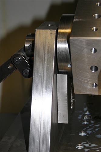
On the other side of the tailstock is a little movable v-block that holds the tombstone until the sliding ballnosed pin can be engaged to hold it securely. Very well thought out!
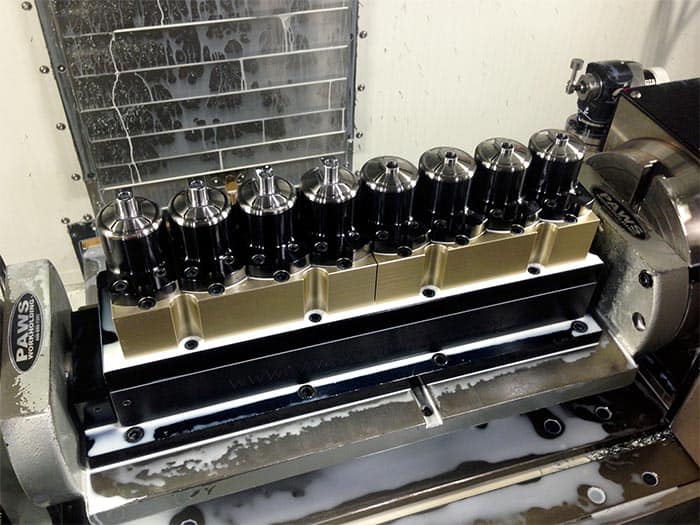
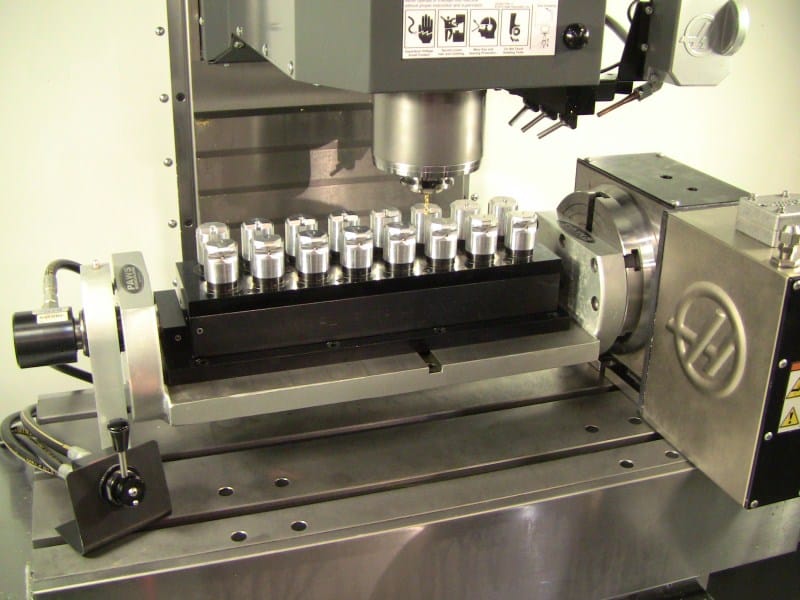
Here’s a neat fouth axis fixture with 5C collets from PAWS workholding…
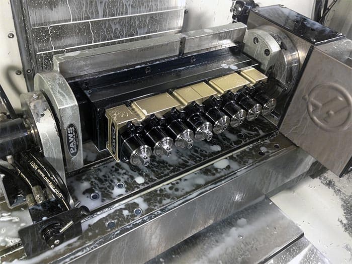
For this part, access on the two sides was important, and the fourth axis makes that easy. Note the lever to release the pneumatic lock on the left.
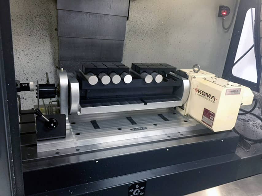
Fourth axis fixture clamping round stock from the side…
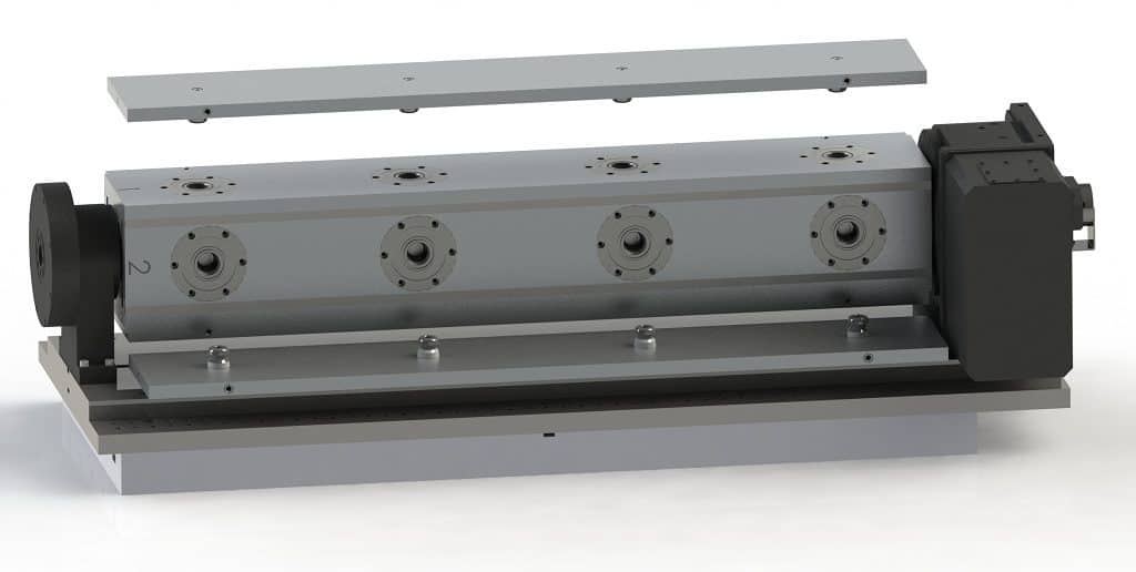
Very slick tombstone trunnion from Stevens Engineering has quick locks for fixture plates.
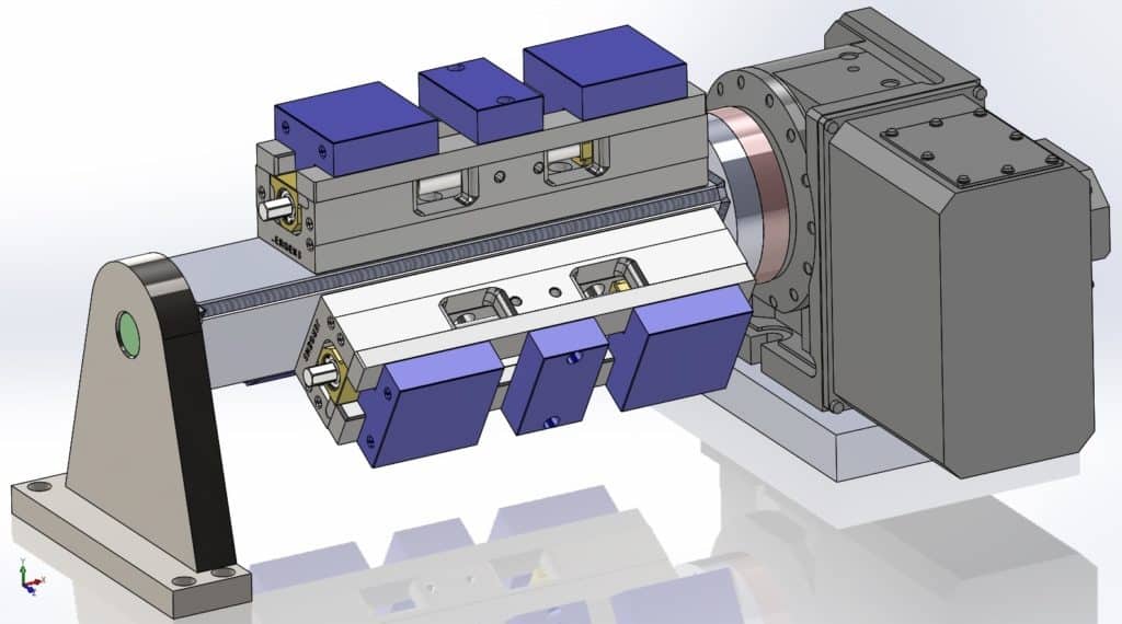
Another neat fixture from Stevens Engineering. If you’ve got a big enough machine, mount 3 two-station vises!
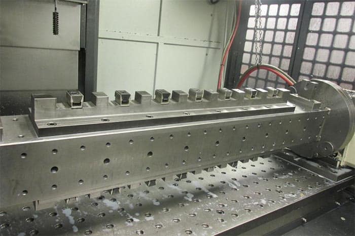
Check out the uniforce clamps on this fixture for holding small parts.
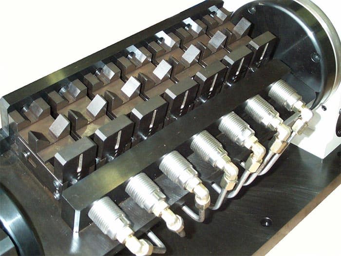
Here’s a very special fourth axis fixture from Intellitool. Parts are supported via V-block cradle and individually hydraulically clamped.
What kinds of neat fourth axis fixturing have you used on your jobs? Share some examples in the comments below!
CHAPTER 7:
DIY 4th Axis Design
For the DIY CNC'er wanting to construct there own 4th Axis, here's are some design notes that will hopefully save time and result in a better 4th axis.

The first decision to make designing a fourth axis is whether you plan to build it around a rotary table with its associated worm gearing or not. Taking that approach is probably the fastest and easiest route, but it will have major shortcomings associated with backlash.
The worm gears in import rotabs may actually have quite a bit of backlash. You can try to adjust it out, and often that results in binding, which can be overcome with a honking big motor, but which will eventually wear out your worm. In the meanwhile, rapid wear will keep you busy readjusting it frequently.
The fancier approach is to use a Harmonic Drive. These are zero backlash devices invented back in the 50's for Defense applications. They're common in CNC and robotics, because they are compact and can have pretty high drive ratios. The other approach one could take is to either direct drive, or use a timing gear pulley setup such as you would often use to gear down the X, Y, or Z axes. I've seen really cool 4th axis setups built in this way out of spindexers or even small lathe headstocks, as well as from scratch.
Since there are a lot of trade offs flying around, I put together a quick calculator in Excel that you can download to do some back of the envelope calculations for the 4th axis. It looks like this:
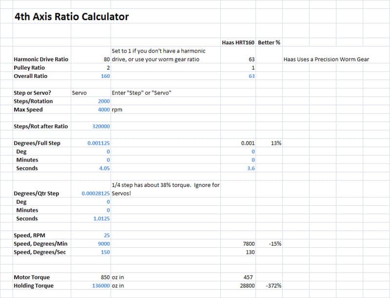
Avoid messing with the blue numbers, they're formulas. Instead, enter your drive ratio for either a Harmonic Drive or the worm gear setup on your rotab, any additional timing pulley ratio, whether you will use a Step or Servo motor, and lastly the motor's torque. The calculator will do the rest and will even let you compare your design to a Haas HRT160 indexer. The numbers I show in the example above represent the design I will likely follow for my own project. I snagged some 80:1 ratio Harmonic Drives on eBay that are brand new:

Harmonic Drive Systems CSF-20-80-2A-GR-SP NEW IN BOX!
I bought two of these units. They were not cheap, but not really egregious either and a Harmonic Drive is just the ticket for a really slick 4th axis. It would be cheaper to use a step motor, so I am still dithering about that, but the engineering calcs show a servo. Performance if I apply an additional 2:1 reduction with a timing pulley setup will be pretty comparable to the Haas. There's oodles of holding torque available with the high drive ratio and the big servo, so I don't know if it is worth adding a brake. I'll probably set up the design to accomodate one and then wait to see if it is needed. My thinking is a motorcycle disk brake caliper and a custom rotor would be an easy add-on, although it may be even easier to fabricate a screw-driven caliper:
Being able to lock the axis opens up some possibilities...
Love the two speed belt drive too!
The starting point of a project like this is a spindle and bearings. Essentially a lathe headstock is being built, and there have been 4th axis projects based on lathe headstocks. My plan for this one is to use bronze bearing sleeve press fit into aluminum. Lots of reports of how nice and tight older lathes with bronze bearings run. It's cheap and easy for a project like this too. The chief disadvantage is if you need to run a lot of rpm, but the bronze with drip oiling is certainly good to 2000 rpm or so. I'm not really working too hard at making my 4th axis act as a lathe, so I should be fine.
Links
Some other's 4th axis projects:
Nice one made by Bob Adams from tapered roller bearings.
Very cool servo driven 4th axis with disk brake.
Be the first to know about updates at CNC Cookbook
Join our newsletter to get updates on what's next at CNC Cookbook.
