CNC Milling Machine Parts Home
A CNC Milling's Axes are attached to the Machine Frame. Their role is to provide motorized motion in each dimension as commanded by the control panel or g-code program through the controller.
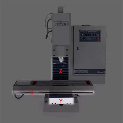
3 Axis CNC
A typical 3 Axis CNC Milling Machine has it's axes arranged something like this:
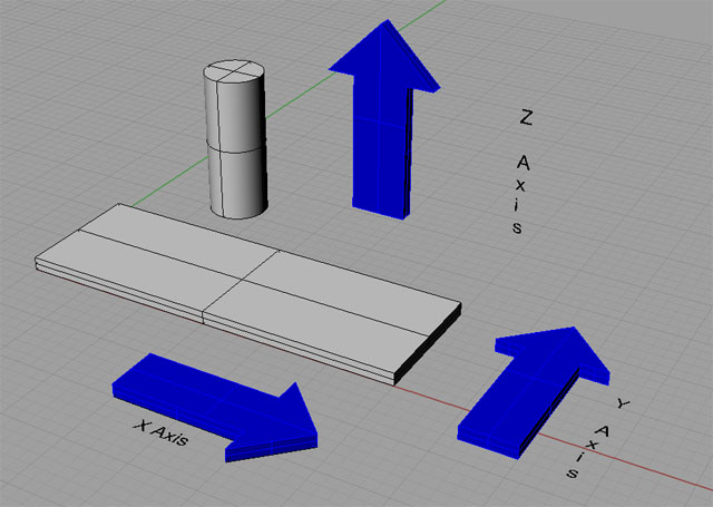
3 Axis CNC...
For more about the CNC Coordinate System, check the chapter in our Free CNC G-Code Course.
More coordinates are also possible. 4-axis and 5-axis CNC Machines are entirely doable.
CNC Axis Components
In order to satisfy its function, each CNC Axis has the following components:
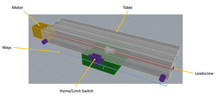
Let's get a closer look at each component and learn more. We won't bother with the table here as not every axis has a table and we already covered CNC Milling Machine Tables.
CNC Milling Machine Ways
CNC Milling Machine Ways provide a low friction precision sliding surface. Their job is to guide the motion so it is properly aligned to the axis and keep things moving freely and precisely.
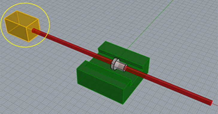
Box Ways / Dovetail Ways
The diagram on the left depicts what are called Box Ways, and these Box Ways in particular are Dovetail Ways because the surface is like a dovetail joint from woodworking. Other shapes besides the dovetail are possible, such as the more rectangular shape depicted here:
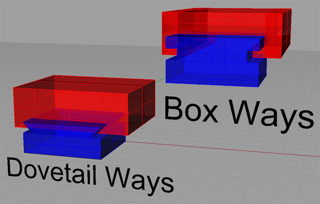
Box Ways are most commonly made of cast iron because it has good properties in terms of metal-on-metal sliding contact. Other kinds of metals such as aluminum are not so good because they have a tendency to gall.
Linear Ways / Linear Slides
Aside from Box Ways, the other type of CNC Milling Machine Way is called a Linear Way or Linear Slide.
While it is possible to fabricate a linear slide from scratch, this is most commonly done for CNC Routers. Milling Machines tend to use pre-made Linear Slides such as these:
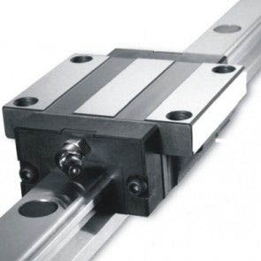
Linear Slide Rail with Travelling Block...
The rail is cut to length and can hold as many travelling blocks as you like. In most designs, there are two travelling blocks per rail and 2 rails per axis.
Leadscrew
The Leadscrew converts the rotary motion of the motion to linear motion. Other CNC Machines such as CNC Routers and Plasma Cutters may use alternatives to a leadscrew, such as belt or rack and pinion drives, but for CNC Milling Machines a Leadscrew is the most common solution.
The Leadscrew must convert rotary to linear motion with as little friction as possible and as little backlash as possible.
Backlash
If you haven't been involved with CNC before, Backlash may be a new concept. It's literal meaning is lost motion. Typically when you reverse direction with a leadscrew, there's a small amount of turning required before the direction reverses to take up the slack in the threads.
CNC Machines are very intolerant of backlash. Getting rid of as much of it as possible is critical to their best operation and performance. We've even published an in-depth article:
[ Anti Backlash for CNC: Ball Screws, Bearing Blocks, and Anti Backlash Nuts ]
There are many ways to reduce backlash. It can never be totally eliminated, but a good goal for any DIY CNC machine is less than a thousandth of an inch (0.001") of backlash. Commercial CNC machines will strive for much lower numbers than that.
Friction
It's possible to dramatically reduce backlash in almost any kind of leadscrew by using a double nut with a spring between the nuts so that the slack is taken up at all times.
Most Manual Machine Tools use ACME thread leadscrews, and it's even possible to reduce the backlash there using a double nut scheme. The problem that arises is friction. The more we tighten things up to get rid of backlash, the more friction it introduces.
ACME lead screws are typically undesirable to unusable for normal CNC backlash tolerances. If you do get them tightened down enough, they're very hard to turn and the nuts wear extremely fast. This requires constant readjustment and is generally unsatisfactory.
The answer to that problem is a special kind of leadscrew called Ballscrew.
Ballscrews
Ballscrews are the ideal leadscrew for CNC because they minimize backlash and friction to the highest degree possible. They're called "ballscrews" because the circulate ball bearings in the ballnut. The ball bearings ride in a groove on the ballscrew, and it's the use of ball bearings that makes the high precision, low backlash, and low friction possible.
Here's a typical ballscrew and ballnuts:
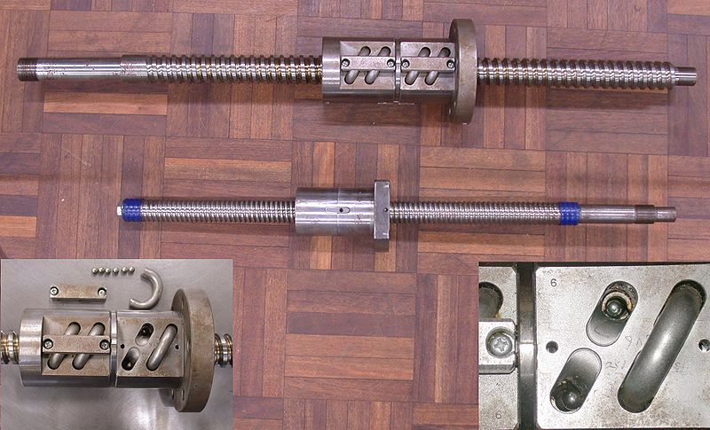
The little pieces of tubing return the ball bearings to the top of the nut once they've travelled to the bottom.
Choosing Leadscrews for Your DIY CNC Milling Machine
Choosing the right leadscew for your CNC Project involves a few tradeoffs. I've laid out a process you can use to select the right ones in my in-depth series on how to design the ultimate benchtop CNC milling machine. Here's the chapter on ballscrews:
[ Ultimate Benchtop CNC Mini Mill: Part 2 – CNC Mechanicals ]
Motor
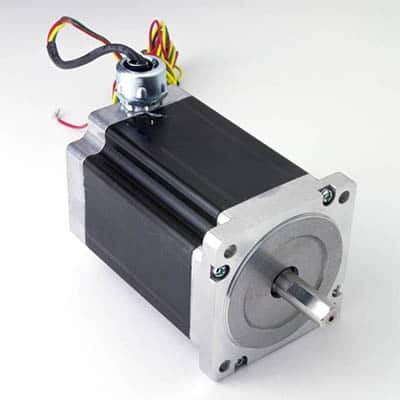
Stepper motor for a CNC Milling Machine...
The photo above shows a typical Stepper Motor for a CNC Milling Machine. Stepper Motors are called that because they're designed to move in discrete steps. A typical stepper motor can move in 200 steps per revolution; about 1.4 degrees per step.
Notice that this particular motor pictured has a waterproof connection. That's important if your machine will ever have flood coolant-coolant and electrics just don't mix very well.
Stepper Motors are the most common motor for DIY CNC Projects, but most commercial CNCs, at least the industrial-quality ones, use Servo Motors.
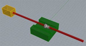
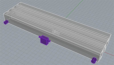
Here's a Servo Motor I used on my project to convert an RF-45 mill to CNC:
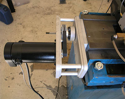
Servo Motor with belt drive...
What's the difference between a Servo and a Stepper Motor?
The primary difference is that Servo Motors are Closed Loop while Stepper Motors are Open Loop.
A Servo Motor has a device called an Encoder attached. You can see it in the photo as the little black box on the back of the servo that has a gray cable connected to it.
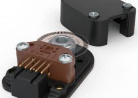
A typical optical shaft encoder for a Servo Motor...
Encoders are sensors that tell the Servo how far it has moved. This signal provides feedback to the controller that offers a number of advantages and increases performance. The feedback is why it's called "Closed Loop".
With a Stepper Motor, the controller tells it to move a step, and it just has to assume it did.
Why wouldn't it?
Most of the time, it does, but when it doesn't, the motor is losing steps. This happens if we ask the motor to do something that's just too hard to do. It doesn't happen often, but it happens more often than we'd like.
Lost steps limit the acccuracy of the CNC Machine.
Servos also perform better in the sense that they produce power over a broader range and often at higher rpms. This can translate to faster axis motions and better acceleration.
Lastly, servos are higher resolution. A Stepper has 200 steps per revolution. For the time being, let's ignore the idea of Microstepping, because it's not reliable as a way of increasing our machine's resolution. Now that 200 steps goes through the leadscrew, and potentially a belt or other drive too, so the actual distance moved in 1 step may be quite small. But, there is a finite distance.
A Servo's Encoder typically has 1024 positions it can measure and even 4096 position encoders are not uncommon. That number, 1024, becomes the Servo's equivalent of the 200 steps, so we can see a 5x improvement in resolution.
There are a lot of pros and cons to Servos versus Steppers. This article gives you the full scoop:
[ Servos vs Stepper Motors / Open vs Closed Loop in CNC ]
Choosing the Right Motors for Your CNC Project
As you can imagine, there's a scientific process you can use to choose the right motors for you CNC Project. It requires a few steps:
1. Decide whether you want Servos or Steppers.
2. Determine the Feedrate range you need for your CNC Machine based on the materials and cutters you will use with it.
3. Determine the acceleration requirements for you machine. Note: A get contacted by folks all the time that want to use G-Wizard to figure out cutting forces so they know how big a motor to choose. Bad News: you'll be sorry if you follow that path because acceleration is really what will determine your machine's performance and it takes a lot more force to accelerate an axis than to merely hold cutting forces on it.
Given the information gleaned in those steps, you can make a very educated choice of what motors to use.
Of course, we've got articles to guide you through the process:
[ Determining Your Motion Performance Needs (#2) ]
[ Acceleration & Cutting Forces (#3) ]
[ Making the final choice of CNC Motor ]
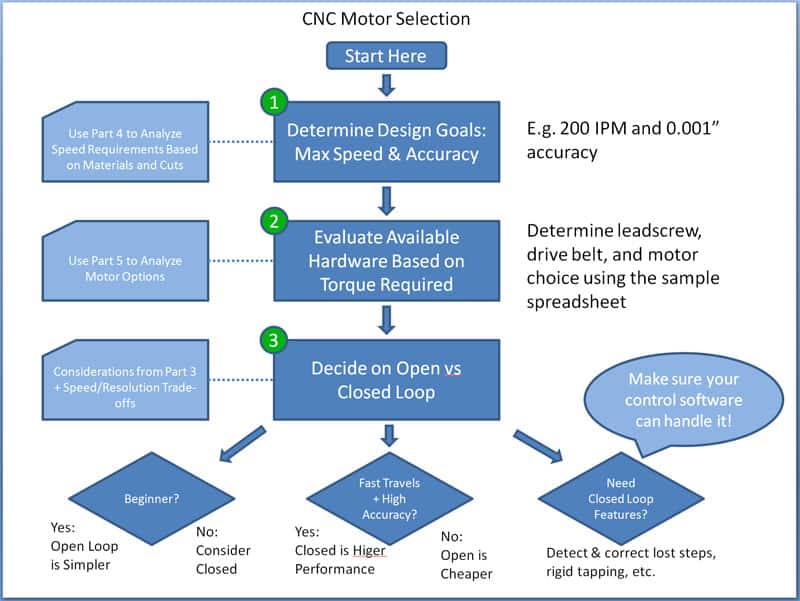
Here's a pictorial summary of the decision making process described in the 3 articles:
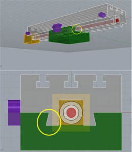
Home & Limit Switches
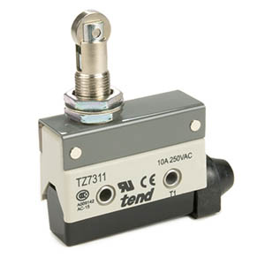
Home / Limit Switch for a CNC Milling Machine...
Home / Limit Switches tell the CNC Milling Machine when it has reached the limit of travel for the axis. The two names imply two purposes:
- Home: This is the "0" coordinate position for the axis.
- Limit: Better stop before we hit the limits and crash!
For most machines, only one switch is used per axis, and it's a Home switch. The Limits are determined in software.
The first thing you want to do with most CNC Machines when you turn them on in the morning is to "Home" them. This means the machine moves to trigger the home switch on each axis so it knows exactly where zero is on that axis.
There's a little fly in that ointment though, especially with the sort of Home / Limit switches used by DIY CNC'ers and on lower end machines. That fly is the repeatability of the switch.
Repeatability means if you repeatedly home an axis, how close does it stop at exactly the same point. You might think it'd be perfect every time, but it's really not. In fact, at the low end, it is so far from perfect that it becomes a problem.
A switch like the one pictured is only accurate to a few thousandths of an inch. Let's say it's +/- 0.005" each time.
Why is that a problem?
Suppose you're working on a job and decide to go to bed. You turn the machine off. Next morning you restart. The machine may be off by up to 0.005" from where it was when you quit. That's quite a big error in CNC Machinist terms.
What this forces you to do is manually rezero the machine with an edge finder or other probe.
Having to do this is not the end of the world, but it's a nuisance and the time consumed costs money for a professional shop.
Much higher accuracy is possible with better switches. Most Commercial CNC Milling Machines use Servos, and they emply the high accuracy of the servo's encoder to radically improve the accuracy of the mechanical switch.
It's nice to walk up to a CNC machine, turn it on, home it, and be ready to keep going on the same job with plenty of accuracy!
Be the first to know about updates at CNC Cookbook
Join our newsletter to get updates on what's next at CNC Cookbook.