The mill-turn machines capture my interest greatly. They represent the finest features of a lathe and a milling machine, enabling the rapid production of intricate parts that otherwise would be less efficient if created using multiple operations across diverse machines. Here's an enlightening video of a Haas CNC lathe manufacturing such a part:
The secret behind these machines is two-fold:
First, they have the ability to treat the spindle as another axis, called the C-Axis. This allows positioning the part with great position to any angle.
Second, they have live tooling. Instead of an ordinary lathe tool in a turret position, there's a miniature motorized spindle that can hold endmills, twist drills, saws, or whatever else is needed.
How does one convert a spindle into a C-Axis indexer?
One obvious answer, used in many machines, is to use a servo as the spindle motor. Think of it as the brute force approach.
Another approach is to use a secondary servo that may be engaged or disengaged. Here is such a setup on an Emco lathe:
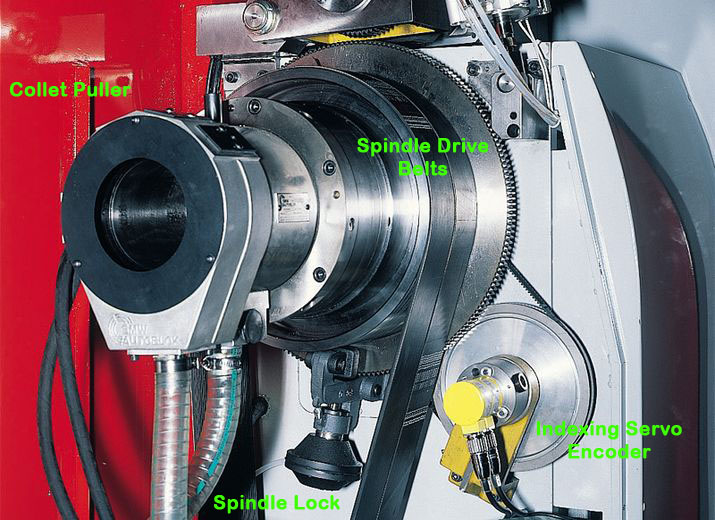 Lathe C-Axis Mechanicals...
We can see a number of interesting functions from the photo:
- There is a collet pulling mechanism to open or close the collet or chuck.
- There is a toothed gear and hydraulic spindle lock. Considerable side force can be applied during C-Axis operations and it is often important to be able to lock the axis while that happens.
- The spindle is driven by a couple of large multi-groove belts.
- There is an auxilliary spindle indexing servo. It's not visible in the photo, but it's encoder (or possibly a transmission to engage/disengage it) as well as the cog belt system it uses to drive the main spindle are there.
Construction is pretty straightforward. Here's another lathe with a sub-servo for the C-axis:
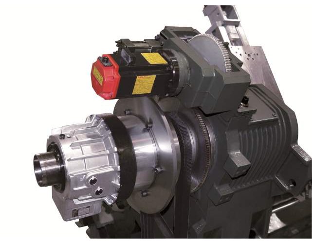 Lathe C-Axis uses a gear-driven sub-servo. Note the disc brake for locking the axis...
The gear-driven C-axis makes me wonder how the avoid backlash? Here's one more that is cog belt driven:
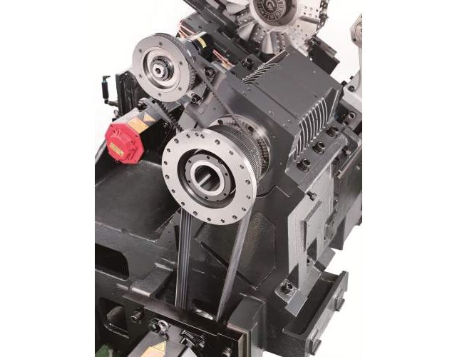
Some sort of clutching mechanism would be used to decouple the C-Axis position servo when the main spindle drive is in operation.
Live Tooling: When a toolholder becomes a milling spindle
Most live tools include a coupler that allows the turret to drive the live tool spindle:
A Live Tool Angle Head: Power coupler is on the right, collet for tool on the left...
A simpler approach adaptable for lightweight work and gang tooling is to use an air-driven spindle:
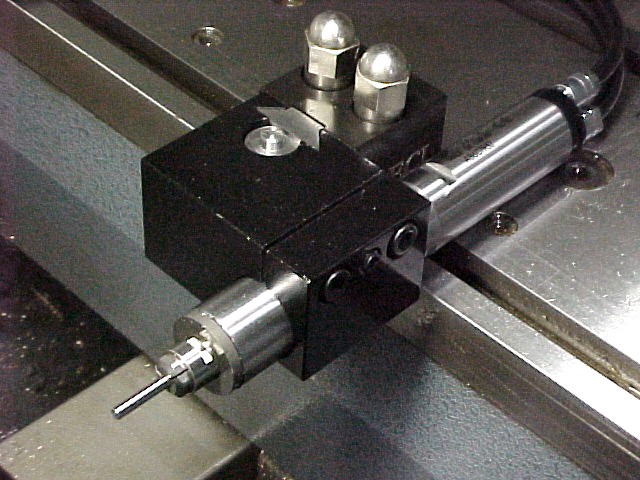 Air-driven spindle on a gang lathe...
Even a small router motor could be pressed into service as this gang-tooling rig on a mill shows:
Be the first to know about updates at CNC Cookbook
Join our newsletter to get updates on what's next at CNC Cookbook.