Anti Backlash Ball Screwws...
While the use of ball screws for cnc is primarily about eliminating backlash, there are other reasons why they're the premier way of driving motion in CNC machines. For example, ball screws are very efficient and offer very little friction or wear.
But, we will start with backlash and ball screws. I'll assume you wonder why you should eliminate backlash (or how much can your stand), you want to build a CNC machine from scratch, or you are converting a manual machine that has measurable backlash. If you have a machine already converted that has the "good" parts (like ball screws), and still have too much backlash, try Part 2 for ideas to solve your problem.
What is Backlash?
According to the CNC Dictionary, backlash is any kind of unexpected play in an axis due to clearance or looseness of mechanical parts. When the axis is commanded to move, the drive motor may turn briefly before movement begins. That delay is the backlash.
Backlash has a variety of causes. The most common is play between the leadscrew threads and those of the nut. ACME screws can have considerable backlash of this kind, while ball screws may have almost none. Another source is any tendency for the screw to move axial in the bearings that hold it, or any other such play in the system.
Precision angular contact bearings with preload are often used to combat this tendency. Gears, belts, and chains can all introduce backlash into a mechanical system. Even loose fasteners or flex in the mounting plates or chassis can be a source of backlash.
Why Eliminate Backlash?
Backlash is a subject that comes up frequently in CNC machine discussions, and it seems machine makers are willing to go to no end of trouble and expense to eliminate backlash. Why is it considered so bothersome?
There are several reasons. First, CNC machines are largely blind and even most closed loop systems can't sense that the axis hasn't moved even though the motor has. A system that has both encoders on the shafts and some form of linear encoder may be able to sense the axis hasn't moved, but even a machine that "knows" the backlash is there suffers from the other problems.
A second issue for backlash can occur while climb milling (for a definition of climb and conventional milling, try our article on the subject).
Climb milling is often preferred to conventional milling because it produces a better surface finish and places less stress on the machine and cutter. However, if an excess of backlash is present, the action of the cutter can operate to pull the workpiece suddenly into the cutter by a distance equal to the backlash.
At the very least this is counterproductive to surface finish and at the worst, it can result in a broken cutter, scrapped workpiece, or even injury to the operator from flying debris. Very bad!
Clearly this one doesn't go away even if the machine knows how to compensate for the backlash. The benefits of climb milling are so great that even some of the later manual milling machines at the high end came with ball screws or "backlash eliminators" just so climb milling could be practiced on these machines. You can still buy retrofit kits today to add ball screws to say a Bridgeport mill for this purpose.
If you don't plan to CNC the machine, make sure your ball screw installation is properly spec'd to avoid "back driving". This is where the friction on the ball screw is so low that it won't hold the table in place against the cutting forces. It's largely a matter of specifying the right lead for the ball screw or in some cases have a friction mechanism on the axis that can be engaged and disengaged as needed.
The last issue is one of smooth continuous machining when direction is reversed. It's possible for a CNC machine to do things a manual operator spinning the handwheels could never do, like cutting a smooth circle. The operator needs a rotary table to do this, but a CNC machine can smoothly operate two axes precisely enough to generate a circle, unless there is backlash. It turns out a circle forces several changes of direction throughout the course of the cut. See the Stepper/Servo/Backlash Simulator below (appendix at the end of the article) for more details of this, but here is an example of what such a cut looks like when there is backlash: 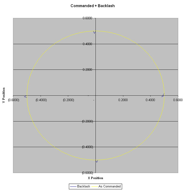
Backlash "Ears": 1" diameter circle, 0.020" backlash on both X and Y axes...
The little kicked out "ears" happen at each point an axis changes direction on the circle.
You can imagine also that when a part is being profiled, the spindle is moving back and forth and up and down to follow the contours of the part. Every time the spindle goes down and then shifts back up, that is a reverse of direction. Backlash is going to cause inaccuracy or dwell marks at those points where the direction is reversed.
As a matter of fact, cutting circles is an acid test for a mill. Try one and see how it turns out to get a rough idea how your backlash is doing as well as a number of other factors.
It's worth noting that lathes have it a lot easier than mills where backlash is concerned. There is no equivalent of climb milling on a lathe, and a reversal of direction need not occur smoothly while cutting as often.
Lastly, the CAM software you'd like to use to generate your g-codes assumes your machine has no backlash. It doesn't produce code that operates the machine the way a manual machinist sensitive to avoiding backlash problems would.
Hopefully we've made a believer out of you that you want to get rid of backlash. BTW, for some applications, such as plasma cutting, the resolution needed may be so low that quite a lot of backlash is acceptable. Try to keep that in perspective as well.
What About Backlash Compensation?
When a manual machinist is faced with backlash, he naturally follows a routine that compensates for it. That routine involves taking up the slack (or backlash) on the handwheels before beginning to cut.
You just have to make sure you feed in the direction you'll be cutting for a long enough distance to take up all the backlash "slack." Once taken up, you're good to go.
Machine control software such as Mach 3 can automatically follow the same routines for backlash. It isn't quite as good as the operator, because it lacks his "feel" of exactly when the lash is gone and instead relies on being told how much backlash is present. It's very hard to get that exactly right and it may change as your leadscrew wears or your machine needs adjustment (for example the gibs need adjusting).
Remember also the problems with climb milling and reversing direction. Our manual machinist probably avoids both because he knows he'll get into trouble. We're not getting full value out of our CNC machine if we force it to avoid climb milling, cutting circles, or the host of other operations that involve changes of direction during a cut.
So, backlash compensation is a weak band-aid for the problem. It's better than nothing, and may tide you over until you break out the checkbook and fix your backlash, but it isn't something you'd probably like to live with long term. If your machine is a lathe, you may be able to live with just backlash compensation.
There are also g-codes that force the motions to take out backlash. These can help a lot when accuracy is paramount, for example when locating the exact position to drill a hole. See our article on exact stop and anti-backlash g-codes for more.
How Do I Measure the Backlash in My Machine?
How do I know how much backlash I have? A DRO is handy if you have one, because it will directly measure how far the axis really moved.
Failing that, put a dial indicator in the spindle (attach one with an Indicol or similar and don't turn the spindle on for Heaven's Sake!). Set it up to read against a 1-2-3 block or other flat reference, put a little tension on it with the handwheel (or manually jogging a CNC machine) to get a reading, and zero the indicator.
Now move the axis in the direction that takes the tension off the indicator a distance that is greater than any possible backlash and read that off the handwheel. Turn the handwheel in the opposite direction exactly the distance you read off from the first movement. Check your dial indicator. The amount it did not get back to zero is your backlash.
A DRO will directly measure the distance travelled, and when I first got my Industrial Hobbies mill, I measured 0.010" of backlash on the X-axis using my DRO. That was when it still used an ACME leadscrew. Backlash once I did the CNC Conversion and installed the ball screws was much better.
Sources of Backlash in Conventional Machines
Your next question should be, "Where is that backlash coming from and what's it going to take to eliminate it?"
In all likelihood, the majority of your backlash is coming from your leadscrew and associated nut.
Most manual machines will use an ACME leadscrew. Because of the nature of these screws, if the nut is made tight enough to eliminate the backlash, it introduces too much friction and the screw becomes impossibly hard to turn.
In addition, the nut is often made of a material that wears more rapidly than the screw, so that it may be replaced more cheaply than replacing the leadscrew itself. Such nuts often have an adjustment to take out some of the excess backlash as they wear. When they don't or when they're not adjusted properly, or when all the adjustment is used up on an old heavily used machine, you get lots of backlash.
It is not unusual to see backlash of 0.005" on a good quality manual machine with ACME screws, and that figure can easily deteriorate to 0.025" or worse on a badly worn machine. There are other sources too, such as the gibs or the mounting of the nut or screw. There can be play in how a hand wheel or motor is attached to the shaft as well. Since the leadscrew is the biggest source of trouble, we'll consider leadscrew alternatives first.
The "Good Parts": Leadscrew Alternatives
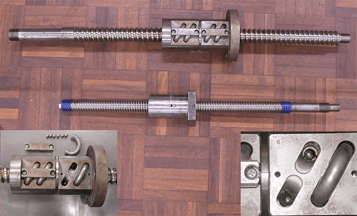
The most commonly discussed alternative to a conventional ACME leadscrew for CNC use is a ball screw. The picture at the top of this articles shows how a ball screw is made. The "nut" uses recirculating ball bearings for extremely low friction and tight tolerances-little or no slop compared to an acme thread.
Ball screws are typically intended for CNC work, and so are made to minimize backlash. Because they turn with a lot less friction than an ACME screw, they can be built to much tighter tolerances.
Ball screws come in rolled and ground flavors, with the latter being more precise and more backlash free. A decent rolled ball screw will deliver 0.003" backlash while a poorly made one has perhaps 0.010". A ground screw ought to be no more than 0.001" and probably should be less. There are ways to reduce this further having to do with the nuts and preloading of oversized ball bearings, which I'll talk about below.
Besides ground versus rolled, ball screws come in different accuracy grades that you should be aware of:
C0 - 3um or 0.0001" per 300 mm / 12"
C3 - 7um or 0.00027" per 300 mm / 12"
C5 - 14um or 0.0005" per 300 mm / 12"
This refers to how close the position will be after the screw has turned through 12" of motion. Note that in this area, there are ACME screws available that are every bit as accurate, so the ball screw has no special advantage here.
Another thing to be aware of is that a lot of machine control software, including Mach 3, has a feature known as "ball screw mapping". This feature lets you measure the true position reached at various points along the ball screw and use it to compensate for errors in the ball screw. This function works very well, and should be taken advantage of if you have the means to accurately measure the deviations. This alone is a good reason to install an inexpensive DRO at least temporarily on your machine until you can get the compensation tables calibrated.
It is also interesting to note that this error can vary as the temperature changes based on the room the machine is in and how hard its working. Companies such as Heidenhain sell special controls based on linear scales (i.e. scales like a DRO uses) that dynamically compensate for such errors on very high accuracy machines. It's quite interesting to read their technical articles about this and gain an understanding of how much error can accrue from such factors as temperature variations. The effects of a fully warmed up machine over the full length of the ball screw was about 0.004", which is significant to many applications.
There are some alternatives to ball screws that I won't discuss here. They're not seen very often, and you can research them on the web if you like.
Nuts, Nuts, and more Nuts
Lots to know about nuts and backlash. The ball nut is where the recirculating ball bearings recirculate.
First, you can get nuts made to reduce the backlash of an ACME lead screw? Wait a minute, you say, we just spent all that time hearing you can't do that without getting too much friction, what gives? Well, it turns out that if you make the nut from Delrin or similar low friction material, you can get rid of a lot of the normal ACME backlash and things work well for a time. These lead screws must be used on smaller machines with limited cutting forces since the nuts are made of plastic (delrin).
I feel this is a good solution of something like a very small travel cnc router table, but I'm skeptical about how well it would work if you need high cutting forces, for example, to cut metal. In addition, such nuts will wear out rapidly and need to be protected from chips and other contamination.
Secondly, one can arrange a scheme whereby there are two nuts with a spring (such as a Belleville Washer) between them to preload the backlash out of the system. This works for ball screws, and it also works for ACME lead screws, albeit with a lot more friction.
This is the normal approach to eliminate backlash with ground ball screws. It adds a fair amount to the cost, but is worth it.
The last trick is to load the ball screw with some oversize balls to take out the slop. This is the normal approach to fine tune a ground ball screw, and it will work to an extent with rolled screws, but there is a problem with the latter. Since rolled screws are not made to the same degree of precision as ground, too much preloading with oversized balls can lead to binding. The grooves are simply not laid out precisely enough to use this method to eliminate all the backlash.
Using these techniques carefully, one should be able to get the backlash in the ball screw itself down to the tenths level (0.0001" to 0.0005") or perhaps less with a very high quality screw.
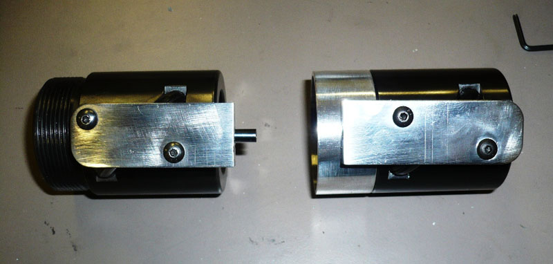
A Well-Engineered Double Ball Nut Solution
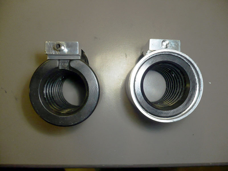
This photo series and CNCZone thread link show how Ray Livingston engineered a double ball nut system to reduce backlash:
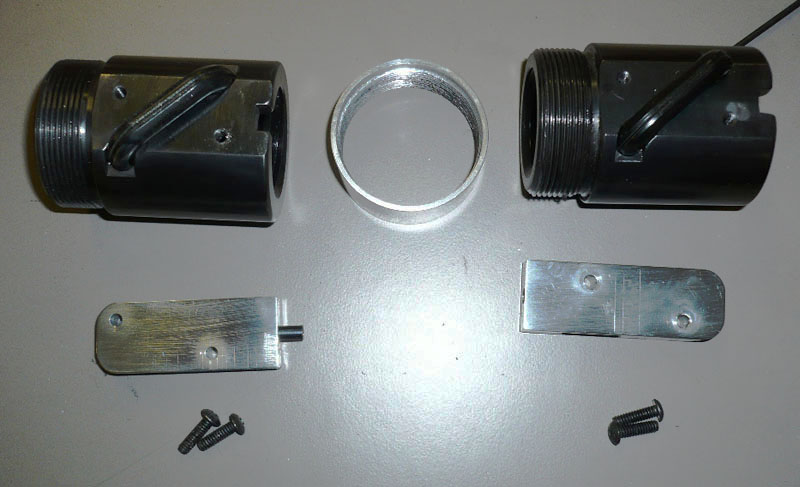
The components. The bracket that keeps the ball nuts from rotating relative to one another replaces the old clamp for the ball return circuits…
A roll pin acts as a sliding guide between the two ball nuts…
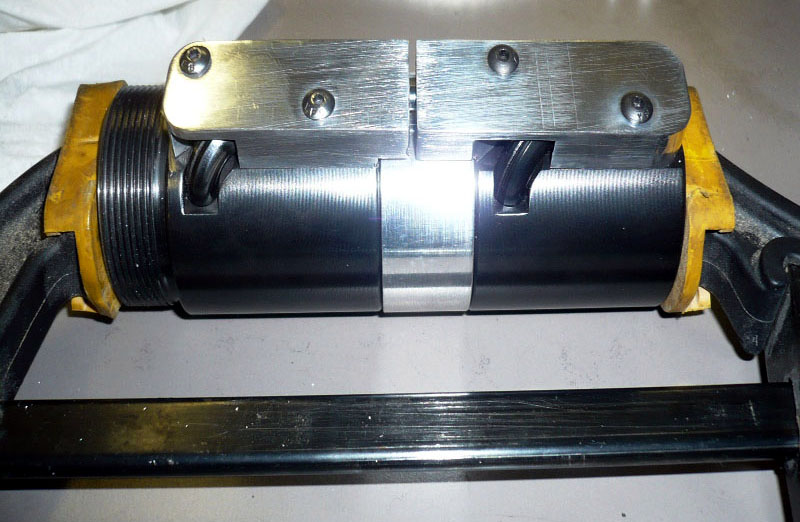
Here is what the ball nut looks like assembled. Disc springs (Bellvue washers) go in the middle to keep the two spread apart and fight backlash…
Mounting the Leadscrew and Nut Properly: Angular Contact What? They Cost What?!??
Now you've get a ball screw with either double nuts or preloaded properly with oversized balls. The next step is to ensure the ball screw is mounted properly. Unfortunately, this is neither an easy, nor particularly inexpensive thing to do.
By design, ball screws are intended to be secured at their driven end by a pair of angular contact bearings. The other end of the screw is either left to float free in some designs, or secured by a bearing in such a way that if the screw expands or contracts due to heat, it has the freedom to do so at this end.
If the ball screw is not held at both ends, there is an upper speed limit beyond which the ball screw will "whip" or flex. That's a bad thing that introduces inaccuracy and wear.
The two angular contact bearings holding a ball screw are typically installed in a preloaded configuration which holds the ball screw firmly and prevents any motion along the screws axis, but still lets the screw turn freely when driven. There is a lot to know to propely design and build a ball screw mounting of this type!
First thing is to get familiar with the bearing maker's literature on angular contact bearings: Barden Timken NSK FAG It's really not all that painful to read through these documents, and there is a lot of good interesting information there. If you learn nothing else, be sure to study the standard nomenclature used to identify these bearings. If you're going out fishing on eBay or the Internet to find them, you've got to know how to identify what you're looking for or looking at.
Now given those resources, we can start to explore some of the issues, or at least some rules of thumb that can be used in this area. First, how does the double bearing mounting look and work? Here's a basic schematic representation:
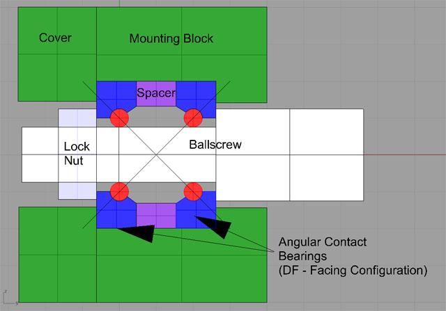 Mounting a Ball screw with 2 Angular Contact Bearings...
Note the crossed lines.
These are the contact angles for the angular contact bearings. Because they are opposed, this provides the resistance to back and forth motion along the axis of the ball screw. In addition, the bearings are preloaded to take out any internal slop. The preload is provided by the spacer between the bearings, the shoulder of the ball screw, and the lock nut that is threaded on the end of the ball screw and bears against the other end of the bearing pack.
The ball screw shoulder and locknut bear on the inner races of the bearing, while the mounting block and cover bear on the outer races. The torque on that nut establishes the preload, and all of these surfaces need to be finished with some fair precision if the end result is to work precisely. The cover is simply holding the bearing assembly in place with respect to the machine, but it does need to be tight with respect to the outer races, so some shimming or spacers may be required.
In this case I have shown the two bearings mounted in the DF, or duplex face to face configuration. The pressures against axial movement are outward, and you can see the bearing balls are supported in that way. You can reverse both bearings to create a DB, or duplex back to back configuration. This still works, and in fact, the bearings will be even stronger at fighting axial movement.
The advantage of the DF configuration is that the assembly can tolerate misalignment a lot better, so this is the recommended configuration in this application.
Okay, let's assume you've carefully perused the bearing literature, you understand the way they're to be employed, how do you select the best bearings for your application? There are a number of selection parameters to consider:
Bore Size
You're going to want a bore that works with your ball screw. In all likelihood, you may have to turn and thread the end of the ball screw. You want as precise a fit as possible for best accuracy. The larger the bearing, the stronger it is likely to be as well, though you can check the specs to see for sure. You can't run the ball screw inside a sleeve to make it fit a bearing that's too large and hope for any accuracy, however.
Contact Angle
Remember the crossed lines above. The greater the angle, the stiffer and better the bearings will be. 15 degrees is the low end of the scale, 60 degrees is the high end of the scale.
Preload
More is better. You shouldn't exceed the recommended preload of the bearing, but bearings are made to different preload specs. Get the ones with more preload for this application. It is amazing how much preload can be beneficial in eliminating as much backlash as possible. Think 500 lbs and up if you really want to control backlash to minute levels. A typical 15 degree contact angle bearing with high preload might only tolerate up to 125 lbs of preload. Alternatives: You can concievably stack 4 bearings instead of 2 in order to do better, but I confess I do not know much about this higher level of vodoo! In addition, while I said not to exceed the preload, if you have a cheap set of bearings (not a $1000 set!), you might experiment with creeping up on more preload. The downside is that it is going to introduce friction and wear that at some stage may be self defeating.
Quality, Accuracy, and Tolerances
The bearing is going to have some slop in it. The higher the accuracy rating, the less there will be. Here is the secret decoder ring:
DIN
JIS
ABEC
Bore Diameter
Width
Radial Runout
Application
P0
Class 0
1
(0.00012)
0.00012
P6
Class 6
3
(0.00008)
0.00012
0.00008
P5
Class 5
5
(0.00008)
0.00008
0.00006
Machine Tools
P4
Class 4
7
(0.00006)
0.00004
0.00003
Machine Tools, Spindles
P2
Class 2
9
(0.00004)
0.00002
0.00002
High Speed Spindles
There is at least one highly regarded low end CNC mill being sold today that uses ABEC3 bearings to mount the ball screws. OTOH, if you want the best, ABEC 7 is the way to go. Note how small the actual differences are between these two grades: 0.00008" runout vs 0.00003" runout. Half a ten thousandth! I can see why for many applications the ABEC 3 works well enough. You need to decide what will be good enough for you, as this particular specification drives up bearing prices faster than anything else. It's easy to pay $1000 or more for a set of ABEC 7 bearings.
Axial Load Rating
If your bearing manufacturer offers this number, you've got the diving rod right there. This is the measurement of what it takes to cause axial motion with the bearing. You want the biggest honking axial load you can get!
Understanding Angular Contact Bearings Specifications for Ball screw Applications
When it comes to mounting these little jewels, keep in mind that you probably want ground spacers between the two bearings and the preload nut probably wants to be ground as well.
All that can be done for you by a qualified shop, or in some cases you can purchase the parts already ground. Try to buy your bearings as a matched pair (they'll say "DUL" or "DUH" in the bearing name) and they won't need the spacer between them either. As mentioned before, you may need to shim or spacer the bearings in the mounting block to make sure they're properly locked in there on the outer races. You will also want some form of dust seal to keep the junk out of your bearings.
Here is an exploded view of a professional ball screw bearing block: 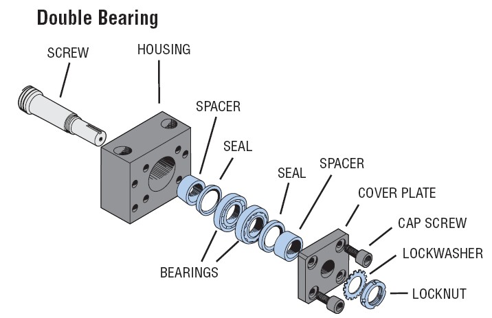 Note that the spacers shown here are not for preload, they simply allow more bearings to be mounted in the block for even greater stiffness, or different spacers would allow some bearing substitutions. Also note that this block has the bearings mounting in DB configuration, rather than DF.
I suspect when you first start shopping for these bearings, particularly if you set out looking for ABEC-7's, your initial reaction is going to be one of discouragement.
Great bearings are really expensive. It's easy to spend $1000 without hardly getting started. Your application may justify it, but most don't.
Here's a couple of less expensive compromise bearings I came across that are worth looking at:
- 7204CTDULP4 : $200 for a duplex pair by Nachi (good name) that can be run in DF config, and are ABEC-7's. The downside? There's only a 15 degree contact angle and the preload is light. Still, not a bad starting point.
- 7204 : $200 too much? How about $24 each for ABEC3's? The downsides-they're not ABEC-7's and they're not a matched duplex pair. OTOH, they have a better contact angle at 40 degrees. Can't tell from this what the preload spec might be, which is bad. Note that what they're calling it, just "7204", it's an incomplete desription by bearing nomenclature standards. It would be like calling a person "Frank". If you know there person well, you know which Frank, but in this case "7204" only tells us the size of the bearing. There's a lot we don't know about these bearings, and most of it is probably to the detriment of performance. You don't want to just go ask for a "7204". Read the information above and learn how to fully specify your bearing if you want the best performance.
What if you do want the all the performance possible? Try to find some bearings such as "7204A5TYDUHP4". They'll have a higher contact angle and preload than the "7204CTDULP4" bearings I mentioned, which as we've discussed makes it a better choice.
The real expensive bearings, the ones designed for ball screw applications on machine tools and used by pros, would be something like "20TAC47BDF". That nomenclature is a little different, but you can find them out there in the bearing catalogs. They won't be cheap, but they have a huge contact angle, 500 lbs of preload, and they are ABEC-7's.
Don't expect to find the 20TAC's sitting in an eBay auction or expect to buy them from a skate bearing supplier. You might get lucky, but it's unlikely in the extreme.
Get ready for some sticker shock on the price, but if they're what you need for ultimate performance, that's what it takes.
Many bearing manufacturers keep these types of bearings in a separate "precision" or "machine tool" bearing catalog. Be sure to sniff around their web sites for those catalogs to see what these bearings are and to learn more about how to employ them in this sort of application. There are endless combinations and trade offs. Shop carefully. Your mileage may vary, and by all accounts, you do get what you pay for!
The other end of the ball screw can be left unsupported, and indeed has been in at least one CNC mill out there, but this limits the speed you can drive the ball screw without whipping. In this case, support it with a normal deep groove ball bearing such as you would use on an electric motor shaft. It's not providing precision, it's just providing support and the leeway for the ball screw to expand and contract axially with temperature changes
I Want to Use Cheaper Bearings Instead of Matched Duplex Pairs
This can be done. The matched pairs have simply had either the inner or outer race ground so there is a differential size between the inners and outers and preload can be had by compressing the shorter of the two until the races from the two bearings are in contact.
One can achieve the same effect by using spacers on one or the other race (but not both!) to create that differential instead of grinding. Doing this is going to require a certain amount of skill and perhaps a lot of trial and error.
The first step is to measure the bearing race deflection with a given amount of preload. Use the amount recommended by the bearing manufacturer for these bearings. This given amount can be placed on the bearings using weights.
Measure how much the races deflect with that amount of weight, and then make yourself a spacer with the same thickness. For a DB configuration (stiffest configuration, but most alignment sensitive), you will be shimming the outer bearing rings. For a DF configuration (less stiff, but more tolerant of shaft misalignment), you will shim the inner bearing rings.
A variety of things can be used to make the bearing spacers, but they need to be very flat, and they will be very thin. In a pinch, aluminum foil could be used, but you'll need to carefully cut it to the correct size to serve. A more elegant solution is to draw up the appropriate washer shape in your 2D CAD program, send it to a laser cutting house, and have them cut washers out of shim stock. You'll want to get some in 0.010", some 0.020" and some 0.002 and 0.005's.
Be sure to consult your bearing handbook to make sure the washers are sized properly before you have them made up.
A note of warning: don't try to set preload by a torque wrench on the nut you're tightening or some sort of calculation on the force that nut delivers! It is almost impossible to get it right. A lot of the force is eaten up as friction, and you will not have enough data to do proper preloading this way. The required information is held closely by the bearing manufacturers. When properly installed, tightening that nut will just tighten down the races on the shoulders and spacers. The nut will come to a stop when things are tight and you should not over tighten further.
A second warning: don't think you can get the preload right by feel. It is very easy to damage your bearings this way! You really do have to rig up a test rig with weights and measure deflection! You should also make sure the bearings are not fit too tightly on the shaft or in the bearing block. A hand slip fit is all you need! Too tight a fit can damage the bearings or make it impossible to accurately set preload. For more thoughts and details on angular contact bearings, check out my mill belt drive spindle project page.
Align the High Spots When Installing the Bearings!
I want to stop here and mention an important point, particularly if you are about to disassemble a ball screw mounting assembly.
Be sure to record the orientation of the bearings relative to the housing so you can put them back exactly as you found them.
When assembling a new bearing system for the first time, most of these bearings have the high spot marked on the bearing. Align the high spots for the two bearings. This ensures that the ball screws moves eccentrically in the same direction as the two bearings rotate, rather than wobbling, and will result in better performance.
Okay, that's the basics. I will assume at this stage you have a good ball screw, proper nut to minimize backlash (or preloaded oversized balls), and a good mounting scheme using high quality angular contact bearings. I would hope your backlash is measuring considerably less than it had been before all those new goodies got installed. Hopefully its under 0.005". The next section discussed refinements to further reduce backlash.
Refinements: Getting Backlash Below 0.005"
If you're looking over this page, I'll assume you have a machine already converted that has the "good" parts (like ball screws), you've gotten rid of most of your backlash (let's say you're down to 0.005" or less), but you still have too much backlash.
What Should I Do?
First, make sure you do in fact have the Good Parts on your machine and that they are installed in the most advantageous way. If you have any doubt, you might just quickly peruse the top of this page again. Okay, so you have the good parts and still have backlash. How to go about diagnosing? Simply put, there are just a few areas that can be sources of the backlash on a given axis:
- Leadscrew & Nut
- Leadscrew and/or Nut Mounting
- Motor Drive Mechanism
- Slideways and or Gibs
- Machine Flexure and Rigidity
Let's look at each one, describe how backlash can develop there, and discuss what you might do to eliminate that cause if you diagnose it as a problem.
Gibs
Let's start here because it is the easiest to work with and likely the source of a fair amount of your problem. I'm assuming you're not running commercial ball bearing linear slides, but have conventional ways of one kind or another with adjustable gibs.
Proper Lubrication is Critical! Start by making sure the slideways are properly lubricated. I hate to leave out that essential point, but while we're on it, be sure your ball screw, ball nut, and angular contact bearings have proper lube as well. Remember, any unnecessary friction can translate into forces that want to bend or deflect something and can lead to backlash. 
Automatic Way Oiler
In fact, this is a good time to bring up the subject of automatic lubing system. Personally, I would always invest in an automatic oiler for any machine I own that requires lube on the ways. I've seen firsthand what happens with inconsistent lube and it isn't a pretty sight.
Unfortunately, adjusting your gibs is a matter of art coupled with much trial and error. I will try to provide some insights.
The recommendation is to run the gibs as tightly as possible but no tighter. Easier said than done.
If they are too tight, that causes the unnecessary friction that then leads to flexure or stick/slip which leads to backlash.
If too loose, there can be slop in the system which translates to backlash and in the worst case, binding and more backlash.
In the end, you need to creep up on it by gradually tightening the gibs and taking backlash measurements at each tightening. The backlash should gradually reduce until you've gone too far, at which point it'll jump back up. Back off in small increments and try again to find the sweet spot, being better informed about when to stop the next time around.
I have often wondered if measuring the torque applied to the adjusting screws wouldn't be a way to make this a little more systematic and scientific. It can take you literally hours to get this right the first time, but it's worth it if you're chasing out the last increment of backlash.
Of critical importance is balancing the forces if you don't have tapered gibs. Tapered gibs have a single adjustment screw that varies tension along the whole length of the gib. Non-tapered gibs use multiple adjusting screws along the length of the gib, and the challenge is to get them all about even. Again, I wonder whether a digital torque wrench wouldn't be a God send to balance that all out properly. Trial and Error: Tighten, Measure Backlash, Rinse and Repeat
In terms of more analytical approaches, I have two suggestions. First, you can simply adjust your gibs while systematically measuring backlash and quit when you have as little backlash as possible and it is still possible to turn the leadscrew. Note that minimum backlash may not turn out to be at maximum gib tightness, so that's why we're measuring backlash each time we tighten the gibs.
Set Gibs Based on Slop Perpendicular to the Axis
A second analytical approach is one I was told is the Bridgeport factory procedure (and is also recommended by Fadal) for setting up the gibs. Use a 0.0001 reading indicator and measure the slop in the slide.
Example: For the X axis, place the mag base on the end of the saddle and put the stylus on the table. At that end of the table push and release. Then pull and release. The difference is the amount of clearance in the slide. Repeat at the other end of the saddle. Adjust gib in a like new machine with little wear to give a reading of 0.0005 (note, Fadal recommends 0.0003", while Pyramid, a rebuilder, recommends 0.0004"). A machine with more wear will have to be checked with the table closer to the end of travel.
The same procedure is used to set the saddle to knee gib. There must be some clearance for the oil film and that film also helps dampen vibration.
On a machine with hardened and ground box ways and turcite on the moving member the procedure is to set the clearance to almost nil. 0.0001 is a good number. This is again a practice of checking backlash while setting the gibs, the difference is the Bridgeport factory knew what backlash to expect on a newly manufactured machine.
Prototrak wants you to adjust their lathes so the cross slide has not more than 0.001" of slop perpendicular to the axis. Use Your Load Meters
Now suppose you have a CNC machine. Are there load meters on each axis? If so, you may have a shortcut to consistent gib adjustment because the load meter will tell you how tight you have them. I installed load meters on my IH mill CNC conversion for this and other reasons. The load meter is just an ammeter on the axis DC supply before it gets to the driver board, so it wouldn't be hard to add these. One account I read suggests setting the gibs so that your axis load is about 30%.
I tried this on an Industrial Hobbies CNC Conversion I built. I had Load Meters on all axes. . I found them to be too inconsistent and also not sensitive enough. Readings would vary quite a lot depending on the exact position of the table. This was all probably due to the poor quality of the ways, but it made the method unusable. I got my best results adjusting for minimum backlash.
Use a Torque Wrench
Southwestern Industries (ProtoTrak) sets the gib tightness on their CNC lathes using a torque wrench. They recommend 15 in/lbs of torque be all it takes to turn the ball screws.
Linear Slide Adjustments
If you are running ball bearing linear slides, and you have two of them on an axis, are they truly parallel, or are they binding up because they're not? The latter will result in flexure if you overpower it with a strong motor and leadscrew combination. You've got to get them parallel to an acceptible standard,
Leadscrew & Nut
The gibs are adjusted to best effect, and you're still on the hunt for backlash. What's next? Is everything bolted up tight with no play or flexure back to the machine? Just check it out carefully, perhaps even disassembling and reassembling to make sure everything is torqued well. Make sure the leadscrew runs parallel to the direction of axis travel, or you're going to get binding at some point that may force flexure and therefore backlash into the system. If you have access to do so, try to place your indicator against the mounting points of the ball screw and ball nut in order to check for small amounts of flexure where there should be none. If you find some, you either need a beefier bracket, beefier mounting method, or less friction in the system (gibs too tight? everything lubed properly? ways in good shape?).
You can also try setting the indicator's magnetic base on the table, and the indicator tip on the ball groove of the screw. Try to move the table by hand. You should not be able to move it far at all (<0.0005" on a commercial CNC machine). If you have too much play here the ball nut to ball screw connection isn't tight enough (need preload? ball screws or nut too worn?) or the nut mounting may be loose.
Do you have a beefy enough leadscrew? This is largely a function of diameter. Check out what companies like Hiwin are using in their Bridgeport conversions. Did you buy a little wimpy ball screw intended for a much lighter application? If so, it is probably flexing when you try to generate too much force with it. I'm hoping you find nothing of value here, because if you do, and you change anything, you have to go back and re-adjust those darned gibs. Doh!
Leadscrew and/or Nut Mounting (aka OMG those bearings are expensive!)
Okay, we spent a lot of time on this above. But maybe you bought cheaper bearings than will suffice for your application. You might want to save this for last, because if all else fails, you will face the expensive proposition of upgrading the (probably already expensive bearings) to some better (even more, possibly much more) expensive bearings. Try to come up with a way to measure just the play in the ball screw versus the bearings. Disconnect the nut from it's mounting, position a dial indicator to read the end of the bearing end of the ball screw, and try to push and pull on the far end. Can you read any play there? Given some of the preload numbers we've talked about (125 lbs to 500 lbs), you might need a fair amount of push/pull force to tell. Do the best you can. If there is too much play here, you may have a problem with the ball screw mounting, very likely the bearings.
You can also run a test with the ball screw turning. Most ball screws with have an indentation in the end. You can rely on the end to be true, but you can place a ball bearing in the indentation and then indicate off the ball bearing. The ball bearing can be held in place with a little dab of grease or superglue. This is one of the best ways to measure the motion of the ball screw in its bearings.
Make sure the bearings are installed properly. Are they facing each other properly in the DF configuration or is one flipped? Check the torque on the lock nut for proper preload. What about the mounting block for the bearings? Are they tight in there, or can they move around? Check the spacers, shims, and fits of it all. Remember we talked about how in the most precise designs a lot of this requires ground precision? How about the ball screw and ball nut? Is there play there? Try the opposite of the prior measurement. Leave the ball nut mounted, but remove the bearings supporting either end. What kind of play is there? Is the ball screw used? Could it be worn? If so, consider reloading some oversized balls, but start in small increments. BTW, there are outfits that will do this for you at a nominal charge and it is a pain, so consider using one. If you have double ball nuts, how about adjusting the preload?
Motor Drive Mechanism
Spring couplers have a bad reputation where backlash is concerned, especially if a lot of torque is required. Oldhams are better if you are direct driving, but a timing belt drive is the best. Make sure your belts are not overly worn and are tensioned properly. Are both pulleys mounted well on their shafts? Commercial CNC machines will use very tight keys and a taper lock onto the shaft. Are we talking about an exotic drive using gears? Fraught with peril from a backlash standpoint. Is it at least a harmonic drive?
Rack and pinion? These can be the ideal solution for long travel situations (such as CNC Routers and Plasma Tables). Just be sure you've taken proper precautions as detailed in our CNC Rack and Pinion article.
If you have a servo related system, don't overlook the possibility that the tuning needs tweaking or that the encoder has some degree of mechanical backlash relative to the motor for some reason even though the motor has no backlash with respect to the screw itself. Perhaps the mounting for the encoder is loose in some way. If the encoder mounting can move or flex, it will affect the feedback it is giving about what the motor is doing, and this can be a phantom source of backlash even when all else is working well!
Machine Flexure and Rigidity
If you are feeding too much force in for the machine, something is going to flex. It could be your ball screw, the mounting for the angular contact bearings, the ball not mountings, or some essential part of the machine that is supporting things. If you get hunting backlash below a thousandth, all this has to be considered. Try some lower speeds for your axis travel and see what effect that has-less force is fed into the system at lower speeds. Try to devise some ways to measure flexure with your dial indicator. There's a weak link somewhere there and you need to find it and beef it up.
I read an account one time of a machine that had a cracked ball screw mount. The suspicion was the riggers cracked it moving the machine. It took a lot of force to make the crack flex, so this fellow took quite a while to track down his backlash, but he eventually did find it.
Best of Luck on this Part!
I know, it's a finicky and painstaking business, and a bit of a black art. Try to follow the path of the forces: the motor turns the ball screw, which is held in position by its bearings. The ball screws moves the ball nut, which is held by it's mounting bracket. Said mounting bracket transfers force to the axis to be moved, and that axis is travelling in ways that apply forces to keep it aligned along a proper and true direction of travel. If all of those things are happily working in concert with the minimum required forces, life is good. If they're fighting amongst one another, that fight is force applied to no good end, and it could well result in backlash. Your job is to track down those little fights and put a stop to them. Approach it as a systematic program of tests and experimentation. Keep a notebook. Measure everything. Try it as many ways as you can think of. Try to think logically about what it all means and how it all fits together. At some point, you will decide things are good enough. Be happy at that stage!
Appendix: Stepper and Servo Backlash Simulator
If you've done some reading and perhaps looked over my CNC Dictionary, you have at least an intellectual idea of the concepts of steppers, servos, backlash, closed loop, and open loop operation. You will have heard that backlash is very bad, and that a closed loop or servo system is much better than an open loop or stepper based system for CNC. What's lacking is an intuitive feel for why? Or, how bad is it really? What will happen if I choose a stepper based open loop system with lots of backlash?
In order to answer those questions, I developed a simulator in Excel that may be used to explore the concepts. The spreadsheet model is pretty simple. It assumes you want to command the machine to cut a circle. I chose the circle because they're inherently a bit of a torture test for this problem because the axes change direction as you move around the circle.
If you'd like to play with the model, download by clicking here. I have samples and conclusions below if you don't want to take the time to play with it yourself.
There is a set of parameters you may enter:
- Circle Diameter, in inches. Pretty self-explanatory, but I like to do 1" or smaller circles because the errors are "blown up" in the graphs, which display larger than 1".
- X and Y Backlash, in inches. Enter the amount of backlash in your system. Check the CNC Dictionary to see what backlash is and how to measure it.
- % Errors: The circle is simulated as 360 commanded moves, or 1 degree around the circumference for each commanded move. % Errors determines what percentage of the time these moves will be ignored due to lost steps or problems in the machine other than backlash. Take a look under "Lost Steps" in the CNC Dictionary to see what some potential sources of these errors are, and be aware that a servo system is capable of "catching up" with the errors again. Note that a lost step occurs in both axes at once, which makes the result unusually symmetrical. It is not realistic-each axis should have had an independent error simulation, but it serves for the educational purposes this simulator is intended for. Another source of inaccuracy in the model is that the lost steps are truly random. In a real machine, once you lose a step, the probability of losing an adjacent step is much higher (perhaps resistance at that point on that axis is unusually high for some reason), so the errors will tend to "clump". Again, this hardly matters for educational purposes.
- Servo Catchup Speed: The Servo Catchup Speed is a crude way of measuring how much of the following error (See "Following Error" in the CNC Dictionary!) can be eliminated in each step. Put another way, if I enter "4" here, 1/4 of the following error will be eliminated each step. This again is exclusive of backlash, and refers entirely to the errors introduced by the "% Errors" parameter. Like the over simplifications on losing steps, this model is also too simple for the real world. For example, it assumes constant speed of error catchup, while a real servo has gain and would accelerate as the error got larger.
The model itself is segmented by columns whose headers alternate blue and yellow as follows:
- Commanded Position: The commanded position is the idealized X and Y coordinates the machine should go to if it performed perfectly and stayed on the circle exactly.
- Axis Errors: Axis errors computes when a random error occurs and step is missed. If the error occurs, the entire step is simply ignored, and the next commanded move is made relative to the prior position. The axis errors are generated completely randomly, and you may wish to experiment with overriding my formulas and forcing constant errors at particular locations or perhaps on just one axis.
- Stepper w/ No Backlash: This block of columns shows the result of running a step motor that gets the Axis Errors as defined, but has no backlash. Step X, Step Y show where the machine wound up, while Step Dev X, Step Dev Y show how far that is off from the commanded position.
- Perfect Motor w/ Backlash: This block shows the result of a perfect motor (i.e. one that never gets an error) with backlash. Backlash X, Y show where the backlash error is injected. Note that the model assumes maximum backlash for an axis whenever an axis changes direction as well as at the outset, which is admittedly worst case. Cmd + Bklsh X, Y shows where the axis winds up, and there is a Dev X,Y to show the error.
- Stepper w/ Backlash: This block adds together the effects of lost steps and backlash. The result can sometimes be hideous if it happens just right, triggering backlash in more than the normal number of places.
- Servo w/ No Backlash: Finally, we show the effects of close loop control, wherein the servo motor "catches up" by systematically correcting out the error over time to get back on track.
I didn't bother to show a servo with backlash. Once you see the differences in just these models, it will be clear what impact each is having. Moreover, I am simulating a closed loop system that measures rotation of the leadscrew, not actual table motion with linear scales, so it can't correct for backlash in that way anyway. The servo system will get the characteristic backlash "ears" just like the idealized "Perfect Motor w/ Backlash."
Above the column headers is a line marked "Max Deviation". It provides a sort of absolute measure of how far from the ideal each model gets at its worst.
There are a set of charts on the "Graphs" tab that show what's happening pictorially. They're on the sheet 2 wide, so scroll vertically to get to the ones you can't see:
- Commanded Figure: A very boring, but perfect, circle.
- Commanded + Backlash: From here on, I show the commanded as one line, yellow, and the others in other colors. On this one, you can see the characteristic backlash "ears" or glitches when describing a circular toolpath:
Backlash "Ears": 1" diameter circle, 0.020" backlash on both X and Y axes...
You can see the little blue "ears" are quite pronounced and would be an unhappy result if you were trying to machine a circle. 0.020" is quite a lot of backlash, but certainly not unheard of.
- Stepper w/ No Backlash: This graph shows the effect of lost steps. As mentioned above, you can adjust the likelihood of losing steps. I have no idea what a reasonable real value is, but after playing with the simulation I can clearly understand why people tune stepper systems to such slow speeds that there is almost no chance of losing a step! Here is a graph with a 2% step loss:
Stepper system losing 2% of steps...
You can see that the problem is once you lose a step, you never get it back and the errors just accumulate, making things worse and worse as the CNC program runs on. The result is scrapped parts or worse, a crash of some kind on your machine.
- Stepper with Backlash:
Wow! Backlash and Steppers are Incompatible!
This graph is particularly glitchy and bad. What's happening is the lost steps are triggering backlash due to direction changes as the machine hesitates. This is probably not that realistic a simulation, but if it was only half right, it shows how bad things can bit if you take a system with lots of backlash and run it open loop.
- Servos with No Backlash: This graph is a comparison of servo vs stepper with no backlash.
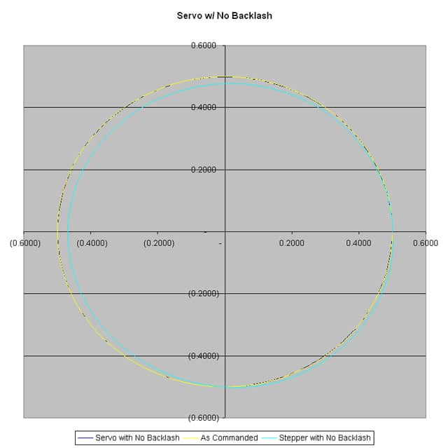
Servo vs Stepper, Assuming No Backlash...
The sample assumes 2% lost steps (very high, puts the stepper in a bad light) and that the servo system can correct only 10% of the error in a given step cycle (seems slow to me, but I really don't know what a "real" number might be). What is obvious is that the servo can track extremely well, and basically stays right on the circle (not quite, you can see little bits of blue), and the stepper does the exaggerated walk of the path that we saw before.

Conclusions
While this simulation is crude, it does give one an intuitive sense of the effects of backlash and closed loop on accuracy.
We can clearly see that backlash introduces "glitches" each time an axis changes direction (which is often on a circle). Yes, there is backlash compensation in some software, but it will force the axis to stop while it winds out the backlash from the screw, and so there will still be some kind of a glitch.
It seems as though backlash can also really trip up an open loop system. We can also see that a closed loop system has the potential of catching up and eliminating the error pretty quickly. The only answer available in an open loop system is that there must not be lost steps. One can come closer to this ideal than many would expect by using big step motors and conservative speeds, adding some gearing down to further increase torque, so all is not lost.
Likewise, Closed Loop does not fix all the sins either. Here is a case where the lost step rate is very high (25%) and the ability to correct for lost steps is slow (taking 100 steps). We are little better off here than with an open loop system (also depicted):
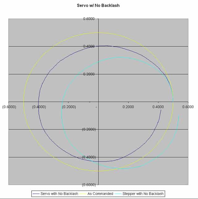
When your servos are too slow to correct following error, closed loop is no advantage...
When you hear someone discussing having to slow down their speeds for their servo system to achieve accuracy, think of this graph. Also think of getting some bigger motors to reduce the errors!
Be the first to know about updates at CNC Cookbook
Join our newsletter to get updates on what's next at CNC Cookbook.