How a rack and pinion drive system works

A Rack and Pinion Drive...
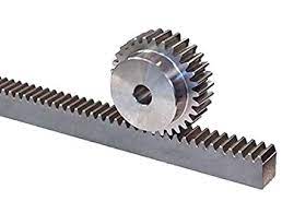
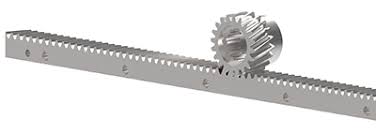
A rack and pinion is a type of linear actuator consisting of a circular gear (the pinion) that engages with a linear gear (the rack) to convert rotational motion into linear motion.
CNC Rack and Pinion
Rack and pinion drives are commonly used in CNC machines, such as CNC plasma tables and CNC routers. They are well-suited for the long travels and specific performance requirements of these machines.
Key Takeaways
-
A rack and pinion is a type linear actuator that is used to drive an axis on a CNC machine.
-
Competing systems include belt drives and ball screws.
-
Rack and Pinion Advantages:
- They are more accurate than belt drive.
- A Rack and Pinion system can carry more load than belt drives.
- They are capable of being driven very fast. This makes it particularly useful on plasma cutters where speed is important.
- Rack and Pinion systems work well on systems with long travels. Many manufacturers feel that any travel over 4 feet starts to be more challenging for ballscrews due to screw whip.
- They are are almost impervious to dust and debris. Simply mounting them on the underside of the machine or the side is usually enough.
- Rack and Pinion systems have high rigidity, particularly on long travel applications
- They are often easier to mount than ballscrews.
- Rack and Pinion costs quite a bit less than ballscrews.
Rack and Pinion Disadvantages:
- They are less accurate and has more backlash than ballscrews.
- Ball screw systems have lower friction than Rack and Pinion.
- Ball screws will wear less than rack and pinion drives, so can last longer.
Rack and Pinion Advantages and Disadvantages
Typically, a rack and pinion drive system would be compared against belt drive at the lower end and ballscrews at the higher end.

Rack and Pinion Advantages:
- They are more accurate than belt drive.
- A Rack and Pinion system can carry more load than belt drives.
- They are capable of being driven very fast. This makes it particularly useful on plasma cutters where speed is important.
- Rack and Pinion systems work well on systems with long travels. Many manufacturers feel that any travel over 4 feet starts to be more challenging for ballscrews due to screw whip.
- They are are almost impervious to dust and debris. Simply mounting them on the underside of the machine or the side is usually enough.
- Rack and Pinion systems have high rigidity, particularly on long travel applications
- They are often easier to mount than ballscrews.
- Rack and Pinion costs quite a bit less than ballscrews.
Rack and Pinion Disadvantages:
- They are less accurate and has more backlash than ballscrews.
- Ball screw systems have lower friction than Rack and Pinion.
- Ball screws will wear less than rack and pinion drives, so can last longer.
Straight gear rack vs. Helical gear rack and pinion system
A helical gear rack differs in that its teeth are angled. This allows a smoother, lower friction movement resulting in better performance than a straight-cut gear rack.

Helical rack and pinion...
Challenge: Rack and Pinion Accuracy
One of the biggest challenges to accuracy is the accuracy with which the gear rack is made. If the teeth are not precision aligned, accuracy will vary over the travel.
It is possible to compensate for this by measuring the actual position and applying compensation in the controller software based on those measurements.
It is also possible to invest in greater accuracy gear racks and pinions.
One area to pay particular attention to is the mountain of the various sections of gear rack and how they fit together.
Challenge: Rack and Pinion Backlash
By default, a Rack and Pinion will have more backlash than a ballscrew. There are various ways to reduce that backlash.
First of all, increasing the quality of the teeth as well as their mounting accuracy will help.
Second, mounting the drive motor so it can be tensioned into the rack will help.
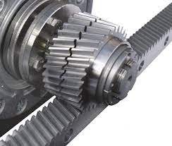
Lastly, the most sophisticated systems use split-pinion drive or dual-pinion drive, where one pinion drives while the other is tensioned to remove the backlash.

Split pinion anti-backlash drive...
Split-pinions are made of two pinion halves — one which is fixed, and one which is axially spring-loaded. During setup, the split-pinion is first adjusted to remove the mesh backlash; it is then preloaded to compress the spring up to the operating load of the application.
Preloading the spring ensures that the spring will not deflect under load during operation. In fact, when the preload is set properly, the spring will not move at all during operation. The only way the spring could deflect further is if the operating load exceeds the preload setting.
Be the first to know about updates at CNC Cookbook
Join our newsletter to get updates on what's next at CNC Cookbook.