This is the second part of our Ultimate Benchtop CNC Mini Mill design series. In the first part, we focused on choosing the Donor Mill. This part will delve into the selection of your CNC mechanical components including leadscrews, ballnuts, motor mounts, and the drive system. In the next edition, Part 3, the focus will be on aspects like motors, motor sizing, drives, and the much-debated topic of steppers versus servos.
Leadscrews (Or should I say "Ballscrews?")
You'll be replacing your Donor Mills leadscrews with some alternate leadscrews as one of the first projects you'll tackle in your DIY CNC Mini Mill. The mill's existing ACME leadscrews, even on high quality manual machines, are just not suitable for CNC. The reason is that they have too much backlash. Backlash is lost motion when you reverse direction of the axis. It comes about from a variety of sources. Typically, there is too much slop in the engagement between the leadscrew thread and the nut. This slop is needed on something like an ACME leadscrew or things are too tight and the screw binds. Backlash can also be caused by play, flexing of brackets, improper adjustment of the gibs on your machine ways, and various other sources. CNCCookbook has an extensive two-part article series on backlash if you're interested in the nitty gritty. I won't spend too much time explaining here. Rather, I'll focus on what the "good parts" are to minimize these problems.
We could spend a lot of time talking about backlash and whether you can get along with it, but that would largely be an exercise in trying to rationalize something you're not going to be able to live with. Suffice it to say that CNC machines can do things manual machines cannot, such as interpolating a hole or contouring a 3D Surface.. Many of those same things involve reversing direction of one or more axes and every time we reverse direction on an axis, backlash comes into play. The backlash causes the motor to move and the control to think that the machine axis moved by the expected amount, but instead, it may move that amount less the backlash. A few thousandths of backlash is too much if you're expecting an accurate machine and decent surface finish. A few tenths is much more what we're looking for.
Now it's true that CNC controls like Mach3 have backlash compensation, but you can't compensate for all moves. Compensation does what a manual machinist doesn, it tries to back up further than the backlash before moving forward so that all the backlash is taken up. But again, if you're trying to cut a circle, the axis direction of one axis or another changes at every quadrant intersection and there is no place to back up to. If you're telling yourself you can live with a lot of backlash via backlash compensation, you're kidding yourself.
The answer to many of these problems is something called a ballscrew. Ballscrews use ball bearings that roll in grooves that serve as threads. Because they use ball bearings to reduce friction, they can be set up with very tight tolerances that eliminate nearly all the backlash.
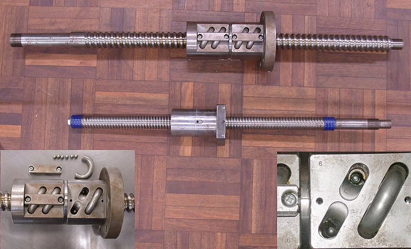
Here's a good look at a couple of ballscrews and their ballnuts. Note the odd little bits of tubing are to take the ball bearings from one end and transfer them back to the other so they don't fall out...
Ballscrew come in rolled and ground flavors, with the latter being more precise and more backlash free. A decent rolled ballscrew will deliver 0.003" backlash while a poorly made one has perhaps 0.010". A ground screw ought to be no more than 0.001" and probably should be less. There are ways to reduce this further having to do with the nuts and preloading of oversized balls, which I'll talk about below.
Besides ground versus rolled, ballscrews come in different accuracy grades that you should be aware of:
C0 - 3um or 0.0001" per 300 mm / 12"
C3 - 7um or 0.00027" per 300 mm / 12"
C5 - 14um or 0.0005" per 300 mm / 12"
This refers to how close the position will be after the screw has turned through 12" of motion. Note that in this area, there are ACME screws available that are every bit as accurate, so the ballscrew has no special advantage here. Another thing to be aware of is that a lot of machine control software, including Mach 3, has a feature known as "ballscrew mapping". This feature lets you measure the true position reached at various points along the ballscrew and use it to compensate for errors in the ballscrew. This function works very well, and should be taken advantage of if you have the means to accurately measure the deviations. This alone is a good reason to install an inexpensive DRO at least temporarily on your machine until you can get the compensation tables calibrated.
It is also interesting to note that this error can vary as the temperature changes based on the room the machine is in and how hard its working. Companies such as Heidenhain sell special controls based on linear scales (i.e. scales like a DRO uses) that dynamically compensate for such errors on very high accuracy machines. It's quite interesting to read their technical articles about this and gain an understanding of how much error can accrue from such factors as temperature variations. The effects of a fully warmed up machine over the full length of the ballscrew was about 0.004", which is significant to many applications. Despite that, many if not most commercial VMC's lack linear scales which are a high end feature. Machinists just deal with adjusting the wear offsets over the course of the day to compensate for these changes.
There are some alternatives to ballscrews that I won't discuss here. They're not seen very often, and you can research them on the web if you like.
To order ballscrews, you'll need to make a few decisions. You need to know the length of the screw, the diameter, the pitch or lead of the screw, the level of precision desired, the type of ballnuts desired, and how the ends will be machined. Let's go through those items to get an idea how to figure it all out.
Ballscrew Length
The length is not too hard to figure. You need enough length for the desired axis travel, plus the length of ballnut (or nuts), plus an allowance on either end for mounting. If you put that all together, you have the ballscrew length. Given you're using a donor machine and a lot of the dimensions can't be changed, another approach is just to have a look at the available room and size the ballscrews accordingly. Your travels will be what they will be. Excessive travel, while it seems wonderful at the time, is not necessarily ideal. The ways are only so long and over-extending a travel just makes it harder for the ways to properly support the table, saddle, or spindle. That extra travel can quickly turn out not to be useful. Commercial VMCs are often dramatically more conservative about this than even good quality manual machines because the know a smaller work envelope will be more rigid all else being equal.
If you size the length based on what fits, be sure to leave some length on one or both ends to mount the ballscrew. At least one of the ends can protrude and probably must to allow the mating of a motor or pulley to it for driving. More on ballscrew mounting below.
Ballscrew Diameter
All other things being equal, bigger is probably better, but it is also more expensive and if too big, will make it hard to fit. The right answer is to base the diameter decision on what's needed to minimize ballscrew "whip". This is the tendency of an unsupported end to thrash around as the ballscrew spins on its axis. The faster it spins and the greater the unsupported length, the more force will be invested in whipping. Larger diameters can counteract this tendency. When we get to the section on mounting ballscrews, we'll talk about supporting one or both ends. Suffice to say that for a long enough and thin enough ballscrew, even if it is supported at both ends, whipping can occur in the middle if the ballscrew is too far towards one end or the other because the middle is still unsupported.
With that in mind, we're still left wondering what the right ballscrew diameter is. Fortunately, the ballscrew vendors provide help in their catalogs to figure this out. What you want to do is search for the term "critical speed", which is the speed at which the ballscrew begins to whip. Ballscrew sellers offer charts and formulas such as this pdf booklet from EMC to help you figure these things out. Here's a typical critical speed graph (actually a nomograph) from that booklet:
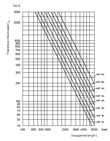
Critical Speed for Ballscrews...
Each diagonal line represents a different ballscrew with a different diameter. The X axis is the unsupported length and the Y axis shows the rpm of the critical speed. Once you know how many rpm you need to achieve your desired travel speeds (factoring in any pulley ratios and the ballscrew lead, of course), you can use a chart like this along with the maximum unsupported length of your ballscrew to determine what diameter is needed to prevent whipping.
Ballscrew Lead or Pitch
Speaking of knowing the rpm, how do we figure all that out and get to know what ballscrew lead works for our machine design? The lead is a measure of how far the ballnut moves in one revolution of the ballscrew, BTW.
It turns out that G-Wizard Calculator has a handy little calculator in it to help with this problem:
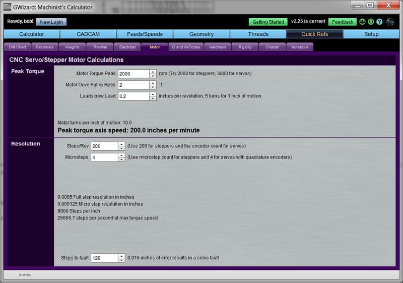
We can back into our ballscrew lead and other info with a little help from G-Wizard Calculator...
What we'd like to do is ensure our motor driving the axis is at peak torque when it is moving the axis at peak speed. That's because the motor will be working hardest at that point and we don't want it to poop out early before we get to peak speed. So, we enter the motor's torque peak rpm first. If you've got a spec, use it, if not GWC says to try 2000 rpm for steppers and 3000 for servos. Next comes a bit of fiddling around. We need to arrive at a drive pulley ratio and a leadscrew lead that allow us to hit the axis speed we want and still have the resolution or positioning accuracy we need. It does us no good to get a pairing of pulley and lead that gives us 200 IPM of rapids speed by only has 0.010" of resolution-that's way too inaccurate for a CNC mill.
Note that leadscrew leads will be limited to the choices available from your supplier-they don't come in an infinite variety. Same with the drive pulley ratios unless you plan to make your own drive pulleys.
To continue designing, after you've entered the motor torque peak, I would next fill out the Steps/Rev and Microsteps fields. The hints make it pretty obvious what to do there. The screen shot is showing a stepper motor example. Having done that, you're ready to play with different combinations of pulley ratios and leadscrew leads to see what can be achieved. The example of the screen shot is actually not too bad. 200 IPM is very decent on a hobby class machine, even exceptional. A resolution of 0.0005" means we can like count on accuracy of perhaps 2x that, so we'll be good to 0.001"-again, very decent on a hobby class machine.
You won't have to play with this long to decide that the faster you want to go and maintain resolution, the harder it is to do so. Pretty soon you need servos because steppers just don't go fast enough and still support the resolution. Some things to keep in mind:
- Don't become too reliant on microsteps for accuracy because they don't have much torque compared to a full step.
- The figure of steps per second at max torque speed may be higher than your control electronics will support. They all have a higher end limit, so keep that in mind too.
Okay, just a little more and you'll be ready to order up and install your ballscrews and ballnuts.
Direct Drive or Pulleys
From the calculations above, you'll know if you need drive pulleys or if direct drive will suffice. For most applications, you'll want the drive pulleys. Be sure to use the toothed cog belts lest the drive pulley be another source of backlash!
Anti-Backlash: Double Nuts, Super-Precision, or Oversized Balls
As mentioned above, ballscrews still have some backlash, though dramatically less than most other screw types. To get the remaining backlash down to manageable levels, we'll want some sort of further measures. We can take it down pretty low by specifying super-precision ballscrews, but if you go looking for some you will quickly find they can be very expensive. That level of expense is not justified on a hobby CNC machine-we can get there much cheaper and more easily!
Another approach is to use some oversized balls in the ballnut. You buy these extra balls and then load them in place of some of the existing balls to take up the gaps that cause the backlash. This works pretty well and is cheap. Here's a video from Hoss showing how he repacks ballnuts to reduce backlash:
Not hard to do and like I said, fairly cheap. Using this method, you'll get the backlash down into the couple thousandths to a thousandth range. Not bad, but we'd really like to get into tenths for a project we're calling the "ultimate". To do that, a better method is to use double ballnuts.
The idea behind double ballnuts is to put a strong spring between the two nuts, typically a Belleville-style disc spring, that exerts a lot of force spreading the two ballnuts apart. Doing so takes out the backlash "slack" in both directions and works extremely well. The downside is you have the cost, complexity, and extra size of double ballnuts. My IH mill uses double nuts and I was able to get my backlash down into the tenths as a result. Here is the ballnut assembly from my mill:
Ballnut assembly, numbers denote the different parts of the assembly...
The numbers denote the different parts of the assembly:
1. This is an aluminum mount that attaches the ballnut, which threads into it, to the saddle, which it is bolted to with 4 socket head cap screws. Make your mounting beefy and solid as any flex will show up as backlash. Also note the piece of copper tubing that goes into the mount. This tubing carries way oil to lubricate the ballscrew and ballnuts.
2. This is one of the two ballnuts, and this one is threaded into the aluminum mount #1.
3. This is the coupling that holds the disc springs that push the two ballnuts apart. The second ballnut threads into it and it, in turn, is clamped on the other end to the first ballnut.
4. The second ballnut.
5. This is a wiper. It's just a set of brush bristles that knock any chips off the ballscrew before they get inside the ballnuts.
You can purchase double ballnut assemblies or you can make them. It's a bit beyond the scope of this post to describe how to make them, but you can find lots of examples on CNCZone. I've also rerun an older post I did on one design so you can see it.
Ballscrew Mounting
A typical ballnut mounting was described above. The ballscrew is held by a combination of the ballnut and ball bearing mounts at one or both ends of the ballscrew. It does us no good to engineer a superb anti-backlash ballnut if the mounting of the ballscrew ends is so sloppy that the screw can move around along its axis. The latter is just another source of backlash. The answer in commercial VMC's is to use high quality angular contact bearings arranged something like this:
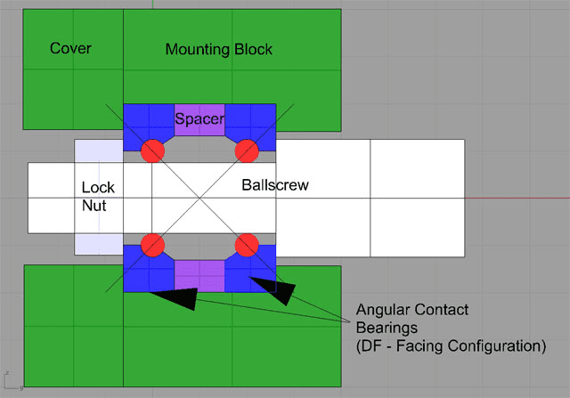
Putting the angular contact bearings back to back like that causes them to resist any motion of the ballscrew along its axis while allowing it to spin freely. You can see from the diagram that you'll need to machine the end of your ballscrew for such a mounting. You need a nicely machined diameter of the correct size for your bearing OD's and then the end must be machined to take a lock nut that will tension the shoulder of the ballscrew against the bearings. The drawing isn't detailed enough to show it, but the ballscrew shoulder and nut ride only on the inner bearing race so that it can spin freely.
Like preloaded dual ballnuts, you can buy ballscrew mounts or make them. If you're new to machining, I'd suggest buying them. They're not that expensive and they'll save you some trouble on a precision part. If you plan to make one, you can read all about the fancy bearing types that are purpose made for this kind of thing. Just keep in mind, for most hobby class CNC conversions, almost any angular contact bearings will do. Forget all the fancy extra preload, precision, and cost. Those cheaper angular contact bearings still won't be the weak link.
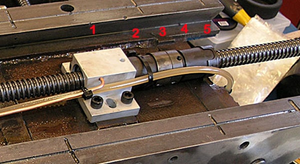
The other thing the schematic doesn't show very well is the ballscrew end needs to extend far enough for a drive pulley or coupler for a direct drive arrangement. Here's the pulley drive for one of the axes on my IH mill:

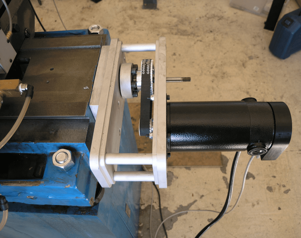
That cylindrical cover held on with all the socket head capscrews houses the bearings that hold the ballscrew...
Let's talk about mounting the non-driven end of the ballscrew. Typically this is done with a simple deep groove ball bearing. The angular contacts are holding one end very tight, so you want the other to be able to slide a little in the deep groove bearings as temperature changes cause the ballscrew to change its length. I recommend mounting both ends. At some point I may look into adding this to my mill, which currently only mounts the driven end. The reason is I can visibly see some ballscrew whip at the non-driven end when I rapid the table from one side to the other.
Mounting Ballscrews on the Machine
Phew! Still with me?
Hopefully you can see that the mechanicals driving the axes of the machine are actually fairly simple once you know how they work. If you have assembled them, the news gets even better-they don't have to be mounted on the machine with great precision. Your biggest concern is that the ballscrews be aligned with the direction of the way motion. You don't want them to be diagonal or they'll bind at one end or the other. Aside from that, you can use pretty simple means to mount ballscrews on your machine. I'd consider it to be pretty close to mounting DRO scales on a machine. Once you've done that you could do this very easily. That's one reason why buying a kit can save you so much time. The kit builder already engineered the bearing supports for the ballscrew and the pulley drive. They already machined the ballscrew ends properly and selected the right ballscrew for their kit. All you have to do is mount it to the machine, which can be done in a few afternoons at most.
In our next installment, I will talk about closed loop vs open loop motion control. We'll get into the eternal steppers versus servos debate.
Be the first to know about updates at CNC Cookbook
Join our newsletter to get updates on what's next at CNC Cookbook.