This is the fifth entry in our Ultimate Benchtop CNC Mini Mill series where we aim to assist DIY CNC enthusiasts navigate the design considerations and compromises for their CNC Mill projects. To date, the installments in this series include:
Part 2: CNC Mechanicals (Ballscrews and Such)
Part 3: Close Loop vs Open Loops (Servos vs Steppers)
We're working towards Motor Sizing, but before we can do that properly, we have one more aspect we need to understand, and that is the role of acceleration and cutting forces on motor torque requirements.
The last thing we want to consider before I wrap up axis motor selection in installment 6 is the role of acceleration and cutting forces. To put it simply, the faster you want to accelerate the axes of your machine, the more motor torque will be needed. Similarly, the bigger the cuts you want to make, the more cutting forces will be generated, and once again, the bigger the axis stepper or servo you will need. I've put together an Excel Spreadsheet you can download to play with these various factors (just click the link to download). There's a lot of math there, and you're welcome to go through it to try to understand how it works, but following all that math is not a requirement to make use of the spreadsheet.
The various inputs used by the spreadsheet are marked with Blue text. The rest is black and bold and should not be edited unless you understand and want to change the math involved. Let's take a look at the inputs:
Motor Sizing Inputs...
If you like, download the spreadsheet and follow along.
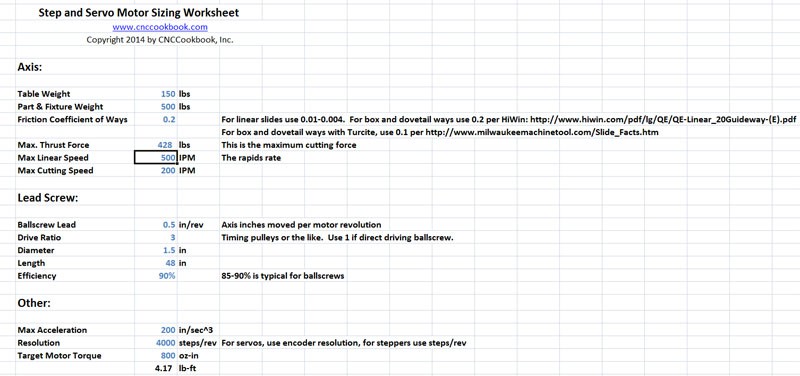
Motor Sizing Worksheet Inputs
Let's have a look at each input and describe what it means:
- Table Weight: How heavy is the axis being moved? Is there a saddle moving as well? If so, include the weight of the saddle.
- Part and Fixture Weight: Just moving an empty table on the mill is not very helpful. Put in an allowance for fixtures such as vises and your workpiece. I put a big number in because that's the weight my mill's table is rated for.
- Friction Coefficient of the Ways: This is a plug-in. Just use 0.2 for box or dovetail ways. If your machine has Turcite (Tormach's and many others do, for example), it lowers the friction. If you are using linear ways with ball bearings, the coefficient is very low indeed.
- Max. Thrust Force: This is the amount of cutting force used. You can get this from our G-Wizard Calculator. The 428 lbs I am using is based on a beefy 3" Face Mill cut-they use a lot of power. This one is a 7.5 HP cut. I just wanted to give something that would definitely be an upper bound for a hobby machine.
- Max Linear Speed: What are your rapids?
- Max Cutting Speed: Max speed for accurate cutting is often less than rapids.
- Ballscrew Lead: How far does your ballscrew move the axis per revolution?
- Drive Ratio: Are you running timing pulleys? How many revolutions does the motor make to turn the ballscrew 1 revolution?
- Diameter: What's the diameter of your ballscrew? That 1.5" is really big for a hobby ballscrew. Yours is likely much smaller.
- Length: How long is your ballscrew?
- Efficiency: Ballscrews are typically 85-90% efficient.
- Resolution: How many steps per revolution does your motor offer? Use encoder resolution for servos and steps/revolution for stepper motors. 4000 is definitely a servo number.
- Target Motor Torque: Thinking of a particular motor? Put it's torque in here and we'll see how well it'll work for your axes.
- Travel Distance: (Just off bottom of screen shot) To calculate reasonable acceleration values needed, we look at a travel distance and figure out how much we need to accelerate if we spend no more than 25% of that distance accelerating to your rapids speed. This gives some idea of what minimum acceleration makes sense for your machine. Too little acceleration and the rapids won't matter because the machine never gets going that fast.
Results
Having keyed in all of those inputs, you're ready to see the results. A lot of intermediate values are computed that can be safely ignored by most.
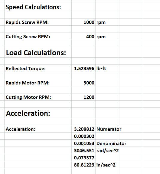
This is where it gets interesting. We get to see what the motor rpms will be at rapids and cutting speeds: 3000 for rapids and 1200 for cutting. Recall from our earlier articles that 3000 is a pretty high rpm for a stepper-it'll likely have fallen off in torque there. This makes this more likely a servo application.
More interesting is the bottom line acceleration value. This combination, with an 800 oz-in motor, can accelerate at a rate of 80.8 inches per second squared. Is that good or bad? Let's look at the acceleration worksheet just above:
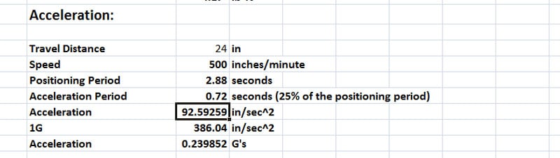
Recall that what this part of the spreadsheet is doing is taking your travels (24 inches in the example) together with your rapids (400 IPM from the original assumptions) and determining how much acceleration is needed to reach the rapids speed in 25% of the travels. BTW, what that means is that from a stop, if you're moving less than 25% of full travels, you'll never get the machine up to its maximum rapids. Acceleration is one of the most important determinants of machine performance. It's actually more important than the rapids because you may never get up to full rapids on many jobs-the distances are just too short and the acceleration capability of many machines is too low.
In this case, we have a predicted acceleration capability of 80.8 in/sec^2 and a desired acceleration rate of 92.6 in/sec^2. We're not doing terribly badly, at least in the ballpark, but we can clearly see we need stronger axis motors to achieve the desired performance. About 900 oz-in would do it. Suppose we have linear slides instead of box or dovetail ways? The much lower friction gives us an acceleration of 103.7 in/sec^2. That's about 30% more acceleration than with the box ways. This is one reason why machines with fast rapids and smaller machines (less room to accelerate in) often prefer linear slides to box ways.
Next installment, we'll bring all this together and finish describing the process for selecting your motors:
Ultimate Benchtop CNC Mini Mill Part 6: Motor Selection Wrap-Up
Be the first to know about updates at CNC Cookbook
Join our newsletter to get updates on what's next at CNC Cookbook.