
Do I need automatic machinery lubrication, a way oiler, or Mobil Vactra 2?
Way Oilers, automatic machinery lubrication, and way oils like Mobil Vactra 2. Does all that sound deadly dull and boring?
It probably does, but proper machinery lubrication is critical to your CNC Machine's performance. I know, because I have seen first hand the "before and after" effect.
If you're a DIY CNC'er you've probably been obsessing over all sorts of design choices that you feel are central to maximizing the performance of your CNC Machine while giving you the best bang for your buck. Way Oilers have got to be WAY down your list of priorities. In fact, probably so far down that you don't even have one on your list.
Big mistake!
I had the "luxury" of owning a Chinese RF-45 mill that I converted to CNC. I say "luxury" with the quotes because except for it's nice large size, a machine like that is pretty low on the CNC Food Chain. OTOH, I was able to make it perform quite well. It just took a lot more work and money than I had expected when I started.
Early on, I decided my machine was going to have servos instead of steppers. Boy did I accidentally learn a lot from that decision!
You see, servos have the ability to measure their motion through a sensor called an encoder. More on all that from our DIY CNC Milling Machine Parts series (which this article is also a part of) can be found in the article on Axes. They key learning tool for me was that if a motion is commanded and the machine doesn't actually move as far as was commanded, the encoder measures that. And, if the difference is large enough, the g-code program is halted and an error is issued.
With stepper motors, you may or may not hear an odd sound, but mostly, things just keep going even though the machine is no longer where it thinks it is and the part being made can turn out to be total garbage (or worse, your machine may crash into something since it is lost). All that without warning.
Now the stepper world likes to say that a properly designed machine never loses steps, that you can clearly hear the steps being lost, and yada, yada. The servo world, meanwhile, can't figure out how the stepper guys put up with their lousy lot in life. I've got an article that walks you through the pros and cons of stepper vs servos too.
What the heck does all this have to do with way oilers? Hang on, we're almost there.
My Chinese milling machine's ways were crude. Forget hand scraping, there were grinder marks. I think they ran it through a surface grinder with a very coarse wheel. Dovetail ways use a wedge called a "gib" to adjust their tightness and fit. The gib is screwed in and you need to adjust it periodically as the machine wears, temperatures change with the season, and on a cheap machine like mine things like cosmic rays and lunar phases as well as my own mood that day all affect those darned ways.
If they were too tight, they would bind up. Too loose? Expect slop and backlash that measurably impacts the machine's accuracy.
And here I was with a tattle-tail servo encoder faulting my machine if those ways were too sticky and the motor couldn't move them. I actually had real data because the machine would stop suddenly and a red light would come on my panel.
One of the very first things I noticed once I had adjusted my gibs and machine acceleration parameters for best consistent performance was that I had to back off and leave a safety margin. I could shoot for the moon-best rapids speed or whatever-but the next day I'd be getting so many servo faults the machine was almost unusable.
Lesson learned-leave safety margins.
You didn't provide any text to rephrase. Please input the text you want to be rephrased.
If I forgot to pump the way oiler a couple times in the morning, the machine was balky and faulted...
The next thing I learned was that when I first started, if I forgot to pump the way oiler (mine was manual), the machine often faulted when making short moves. Welcome to an effect called "Sticktion"!
Sticktion happens because friction is higher between two stationary surfaces than it is once they're moving relative to each other. Your car's ABS brakes keep the wheel from locking because once they're locked, they slide over the asphalt and your brakes exert less friction to slow the car. Same with your machine's ways.
That's why jogging an axis a thousandth of an inch or less at a time to line up an edge finder when setting up a job was the most likely time for my machine to fault. Especially if I hadn't pumped some way oil in.
If you want to help your machine perform as well as it can, it needs a way oil system. Hand squirting oil into ports is barely acceptible on a manual milling machine, but CNC moves the axes so much more, so much faster, and so much more precisely that you need automatic way oiling to make it work well. The more friction there is in your slideways, and the more performance you want to extract despite that friction, the more you need an automatic lubrication system.
Automatic Way Oilers keep the friction consistent so the machine can be tuned to deal with it. They also reduce the wear and tear on your machine's ways.
Got it? Okay, I will move on from the sales pitch. Let's talk about how these things work.
Automatic Lubrication System Components
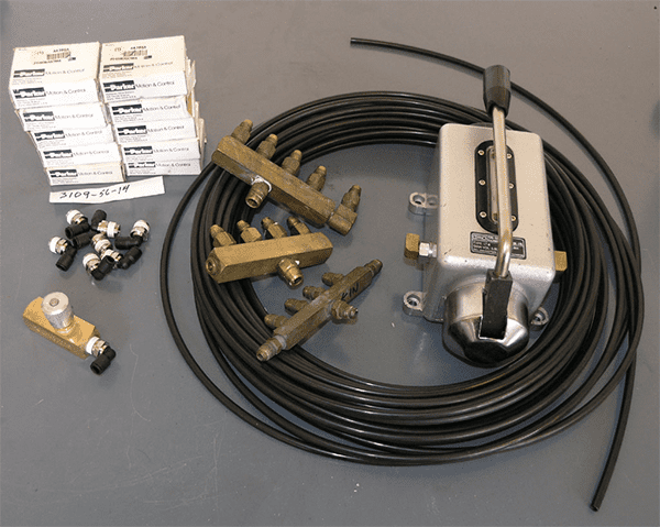
The bits I started with when I built my way oiling system...
The photo shows the bits I started with when I built my way oiling system. There's a manual way oiler (pump), flexible tubing, push-on connections, and metering valves.
Flow Control Valves and Metering Orifices
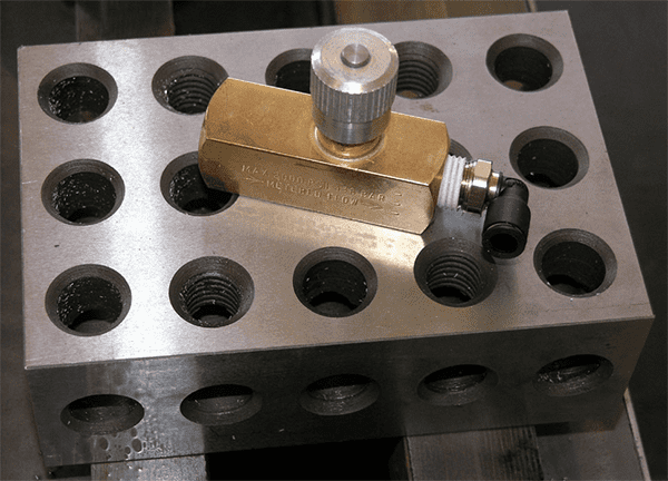
The valve pictured is called a "Flow Control Valve." The way oil that travels through the plumbing of your centralized lube system will seek the path of least resistance. If you just hook them all together with no flow control, some outlets will get a whole lot of way oil and some very little.
You won't see Flow Control Valves on a commercial CNC. They use Metering Orifices in the different passages to equalize the flows. That makes for a much more compact, but non-adjustable system. The DIY project needs the adjustment until you get good flow everywhere. In theory, you could then see how far each valve was open and replace it with a metering orifice of corresponding size.
Either way, you need to equalize the flows.
Way Oilers, Lubricators, and Pumps
Way Oilers, also called Way Lubricators, pump the way oil into the system under pressure so it flows everywhere it needs to go. They typically also include an integrated reservoir that is either clear or has a site glass so you can see when you need to top off the reservoir.
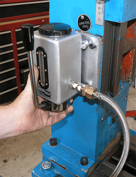
Manual Way Oiler
My first Way Oiler was a manual unit with a pump handle on the side. Give it a few pumps while jogging the axes and you're done. Just don't forget! And BTW, how often should I be pumping while a job runs?
I won't have a machine without buying the automatic way oiler for it again. A Manual Oiler is better than nothing, but not really good enough in the end.
Automatic Oiler / Automatic Lubricator
Here's a typical Automatic Oiler:
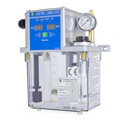
It runs on a timer to ensure consistent deliver of enough oil. That particular one is the unit that Tormach sells for their machines.
What is Way Oil (Some call it Slideway Oil)?
Given the basics of automatic oilers, let's talk a bit about Way Oil. First, you can't just load up any old oil in the machine and expect good results.
Way Oil has been formulated with specific properties:
- It's a hydraulic oil.
- It contains chemicals called "Tackifiers" that make it stick to the surfaces and not run off. For example, your Z axis has vertical ways. Oil is slippery by design, so it'd be hard to keep much on your vertical ways without tackifiers. Having an oil properly formulated with Tackifiers means you don't need to use as much as it stays where you want it. We'll talk shortly about what happens when way oil moves on from your ways.
- Remember that talk about "Sticktion"? Modern Way Oils are formulated so the difference between static (non-moving) and dynamic (moving) friction is much lower. This helps ensure a continuous and smooth transition from rest to movement and typically also makes the static friction lower so starting an axis moving is easier. Mobil has a pdf that'll talk your ear off about this stuff.
- When Way Oil leaves the ways, it generally winds up in your coolant. After all, the coolant nozzles are washing down the machine constantly, so that coolant washes the way oil it encounters into your coolant reservoir. Nasty things happen if it's left there. We'll talk about Tramp Oil in a minute, but for now, realize that Way Oil is formulated so that it is easily separated from your coolant.
Way Oil is no ordinary oil, eh? So where do I get some?
Gold Standard: Mobil Vactra 2 Way Oil
The Gold Standard in Way Oils is Mobil Vactra 2 for most DIY CNC'ers. Mobil actually has 4 different formulations, but Vactra #2 is the one we see recommended most often:
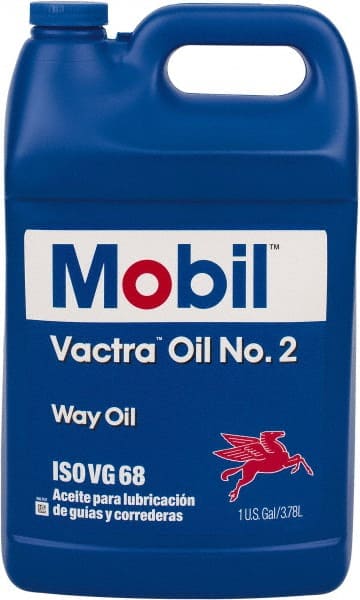
Vactra No. 2 is available from many sources, even Amazon, where it costs about $50 a gallon as I write this. I hear you thinking, "Dang, that sounds expensive, isn't there something else I can use?"
Alternatives and Mobil Vactra 2 Way Oil Equivalents
The standard alternative to Vactra people recommend is chainsaw bar and chain oil. 4 quarts of Husqvarna will set you back $26.40, so it's definitely cheaper.
Here's the thing: all those special formulations and additives that make Way Oil what it is are missing from bar and chain oil. It won't work as well. If you have a cheap Chinese CNC Machine that doesn't run flood coolant, you could consider the bar and chain oil. But if you run flood coolant or if you paid anything much at all for your CNC, why do it?
A gallon of Vactra lasts quite a long time, even with an automatic oiler.
Tramp Oil: The Dark Side of Automatic Way Oilers
It's time for me to make brief mention of Tramp Oil, the Dark Side of Automatic Way Oilers.
When Way Oil leaves your machine's slideways, it's next stop is going to be your coolant reservoir if you run flood coolant. And since you're probably running water soluble coolant and not oil, the Way Oil will want to float on top of the water soluble coolant. It'll spread out into a thin film that covers the entire surface. That film prevents any oxygen from passing through, and in the process, it creates an ideal environment for anaerobic bacteria to grow.
Once you have a thriving colony of those nasty bugs, they emit all sorts of foul smelling odors into your shop and machinery. You don't want that!
I've got a whole article on how to build a simple Tramp Oil Skimmer that will save the day. Check it out:

Tired of stinky coolant?
[ Build a Powerful Tramp Oil Skimmer ]
DIY Automatic Machinery Lubrication
Here's a rundown on my project to create a one shot oiling system for my Industrial Hobbies RF-45 CNC Mill project. I completed this many years ago and before I had a CNC machine. Hopefully it will help a DIY CNC'er with their own project. It wasn't hard to do at all.
Raw Materials
Vinyl oil-proof tubing. 100′ roll, cost $20 on eBay. Box of Legris push-on fittings and some Parker Flow Control Valves from eBay. One shot oil pump, slightly used, still in good working order. Collection of brass manifolds from eBay.
eBay provides all the components needed to create a one shot oiling system...
Flow Control Valves have a check valve in them so the oil can only flow one way. You want a check valve so the oil shows up right away when new oil is pumped into the system.
It's convenient to build that in with a valve so I can fine tune how much way oil is going to each lube circuit. The IH mill will need the following lube circuits:
- X Axis: Left & Right Ways, Ballnut
- Y Axis: Left & Right Ways, Ballnut
- Z-Axis: Left & Right Ways, Ballnut
For a total of 9 circuits. In terms of fittings, this means 9 fittings to thread into the base castings, 9 check valves, and a manifold with associated piping. There will also need to be a couple of fittings and tubing to connect the pump to the manifold.
Cutting Axis Oil Distribution Grooves
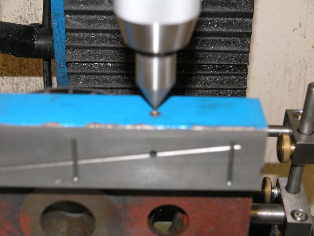
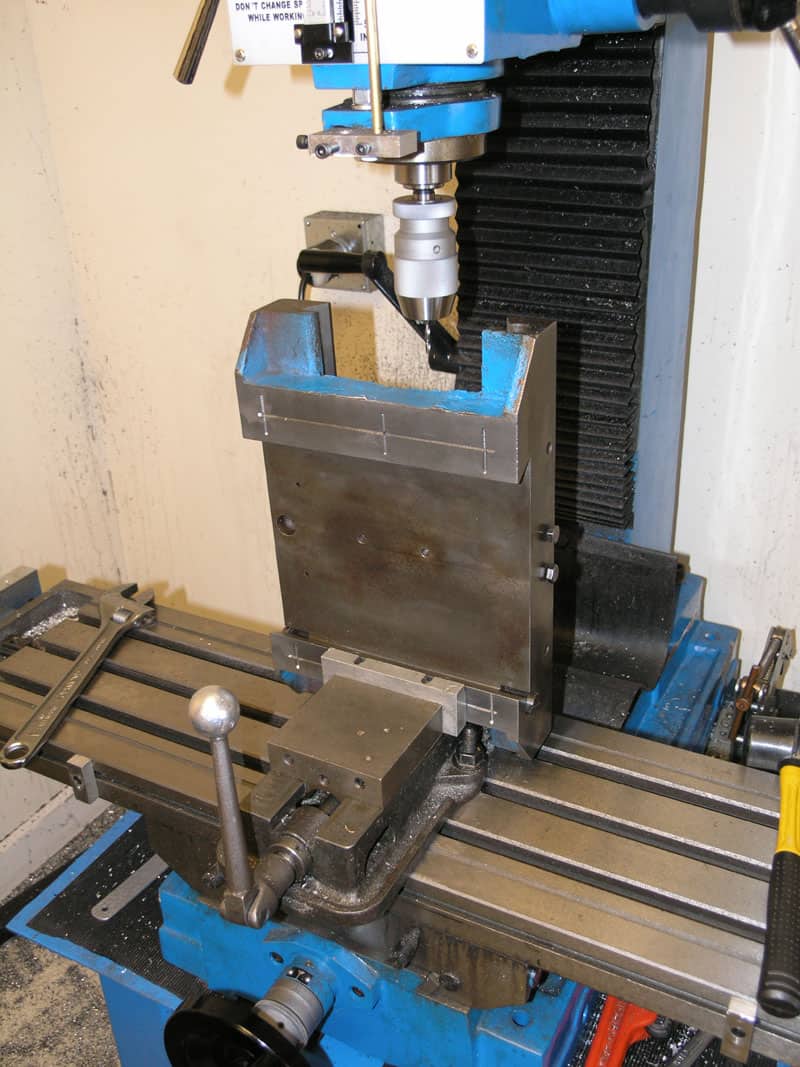
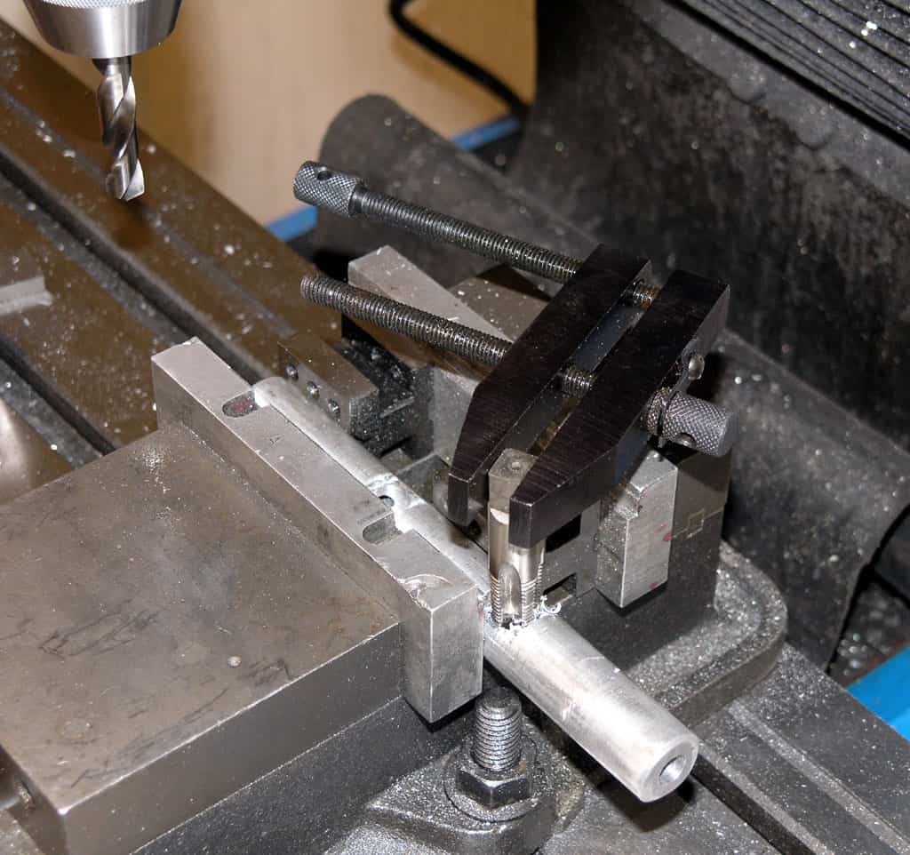
I started out this project modifying the Z-axis. I used a 1/8" ball mill to cut oil distribution grooves on either side:
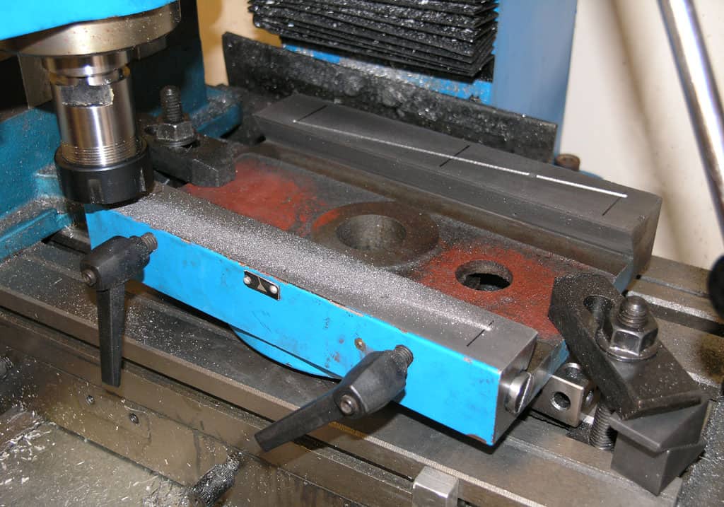
Here I'm cutting the two long angled grooves. The intersect the existing oil passages, which I'll use to inject the oil...
I may have failed to mention, I have 2 of these IH mills. A second one became available nearby very cheap and it seemed a good idea at the time. Would've had to borrow machinery elsewhere to machine the distribution grooves otherwise.
I assembled the Z-slide on the column with gib and just injected through the existing ball ports to see how they worked. Oil distribution was excellent! There was immediately a nice even layer of oil laid down over the entire width of the ways. The slide became noticeably easier to slide even with the gib set tight.
The Y-aixs. I had a couple of minor issues. I got a little too exuberant on the feed and broke an endmill. Left no impact on the slide groove at all, but it damaged my collet slightly. Bummer! Second issue is that I ran out of travel and had to shift the table to drill the second groove set.
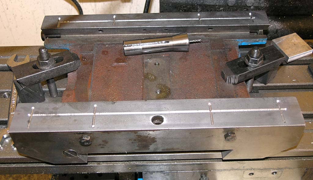
Last set of grooves for the X-axis. Be sure to avoid the hole in the middle of the bottom way. That's for access to an additional mounting bolt for the Y-axis nut.
Plumbing to the Grooves
Plumbing involved first adding fittings to the original milling ports on each axis plus connecting those passages to the new oil distribution grooves.
 No need to be super accurate locating this hole as we are drilling a much bigger hole. I just used a spud to help line it up quickly.
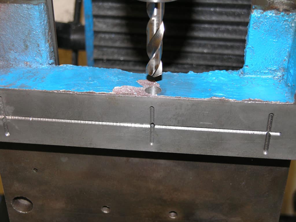
First line up on the old ball oiler location with a spud. On the Z-axis, this hole goes all the way through already (nice!). So we just get rid of the ball oiler (mine had to be drilled out)...
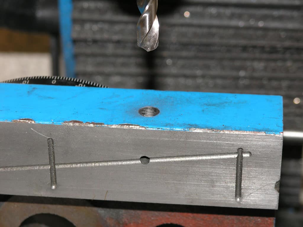
And now drill the hole you'll tap for the fitting. Did you use the best hole size for the tap? G-WIzard will tell you what that is!
And tap. That fitting will be in the way of the gib locks, but I won't be using them anyway. I will likely put bolts of the same size into the holes to block them off...
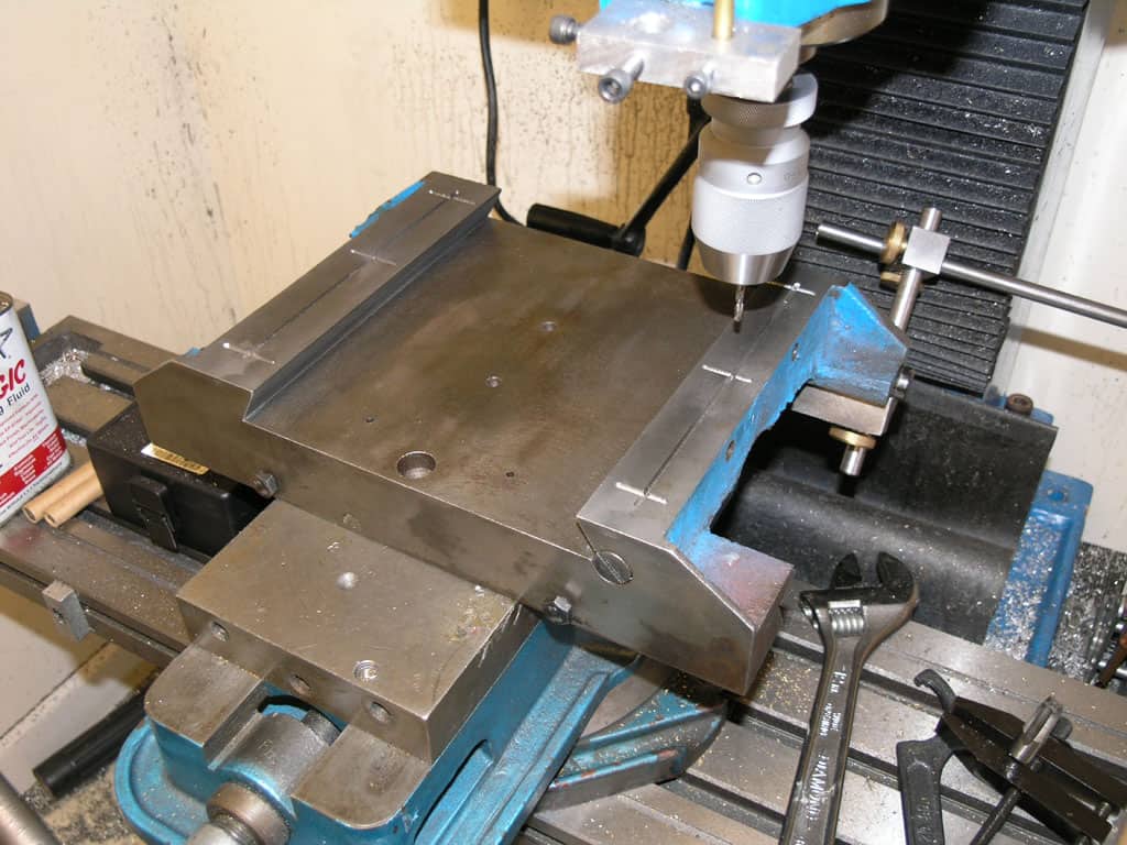
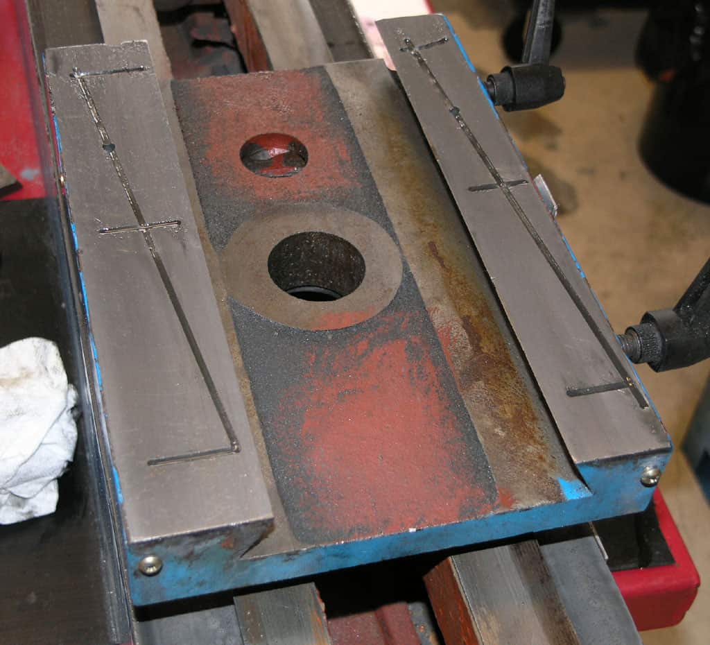
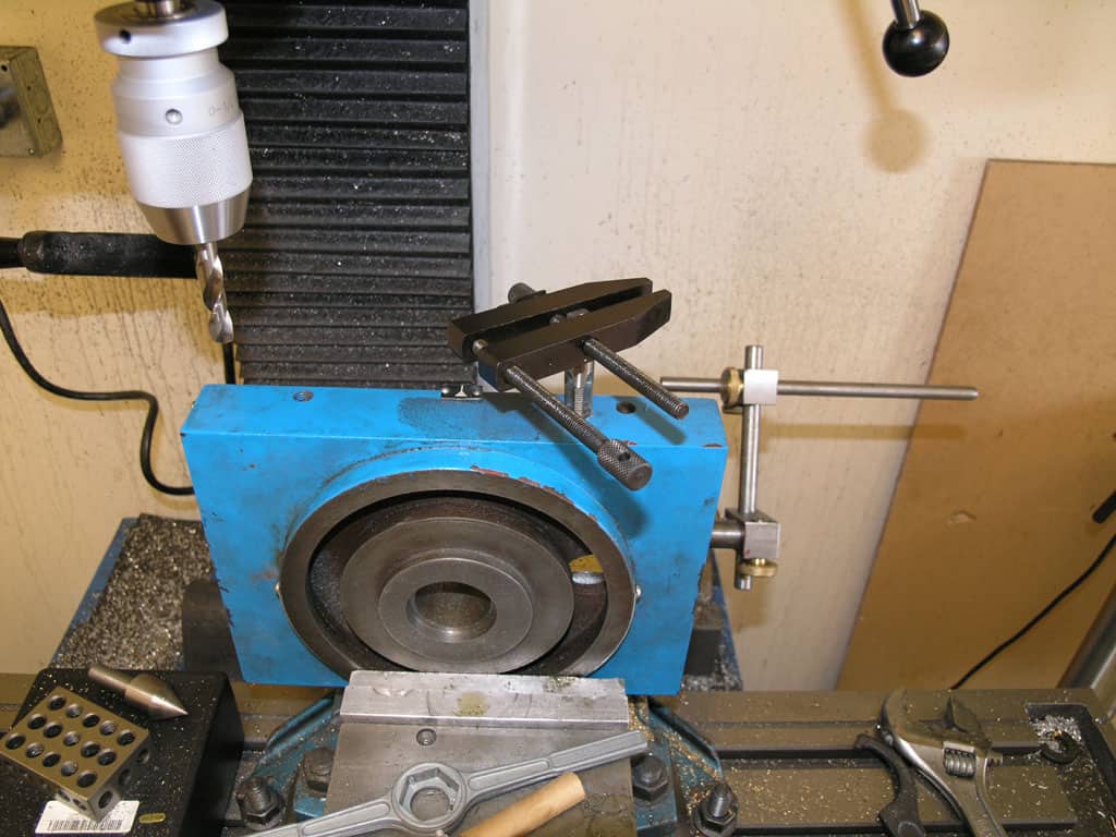
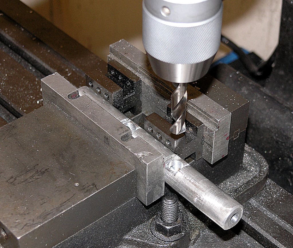
The saddle has no handy holes to work from. I'm drilling at the intersection of the middle cross grooves and centerline groove. The saddle is held by gently opening the Kurt vise with aluminum jaws against the ways. All holes are 0.450" deep.
With both sides drilled, it's time for the cross passages. My 6" Kurt was too big, so I took it off the table and installed my 4" Kurt. The vise has to fit between the X-axis slides that stick out. Not many machines with this much Z-travel!
Swap bits (almost not enough vertical room with my big keyless chuck!) and drill the fitting hole you will tap...
Note the cross-connecting hole I drilled before this one.
The X-axis goes pretty much the same as the Y-axis did. Be careful about putting the fitting too close to the center-that's where the limit switch mounts. You can also go in from behind as Thomas Powell did. It will make for a neater installation, but I had doubts about my ability to tap the fitting holes with so little clearance, so my fittings are all on the outside.
Did some thinking about how I'll run the tubing. Essentially I plan to put in two manifolds-one on the X-Y saddle and one on the Z-axis saddle. Attached to the manifolds will be the flow control valves so I can individually meter each passage for the proper amount of oil. I'll mount the one shot pump on the mill column and use flexible tubing to connect to each manifold so that these two tubes are the only ones moving-the rest of the plumbing is fixed. Access to the X-axis ballnut is easy as there is a large under-table gap. I may drill a hole through the saddle to allow flex hose to go underneath for the Y-axis ballnut. Same with the Z-axis ballnut. So, we'll have a 6-port manifold on the X-Y saddle and a 3-port on the Z-axis saddle.
X-Y Manifold and Plumbing
I wound up making a manifold, and as it was a long piece of alumimum rod needing a center hole all the way through, I needed a bit longer than I had on hand. So, I used it as an excuse to try my hand at a homemade D-bit:
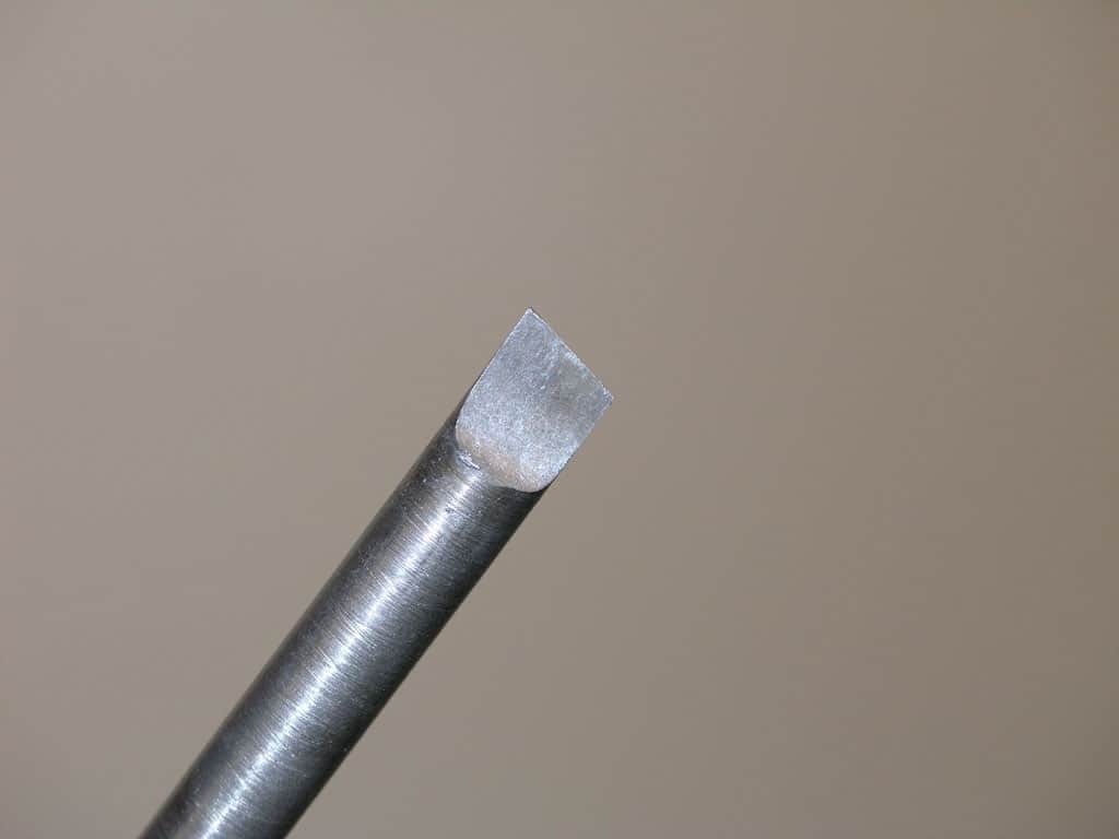
A D-Bit I made to bore the center hole in the manifold...
It cut fine, but loaded up with chips so fast it was a very slow process of having to withdraw every quarter inch or so to remove the chips. It seemed like it took hours, though it was probably only an hour and a half. Next time I'm ordering an extra long twist drill!
I took a 3/4" endmill and made cuts, then drilled with 7/16". The flats make for better drilling and give the fittings something to seat against.
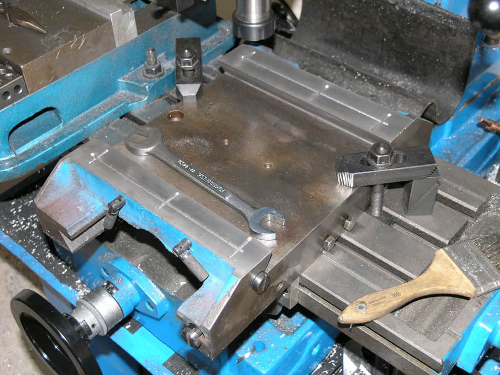
Since my tap wrench isn't big enough for this chunky 1/4" NPT tap, I used a machinist's parallel clamp...
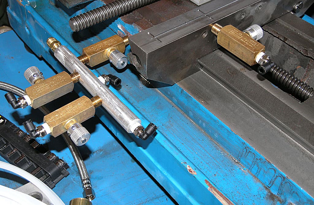
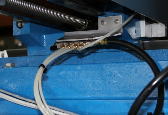
Here's what the manifold looks like trial fitted with the flow control valves and Legris push-on ells. I'll be using translucent tubing so I can verify visually that the oil is flowing...
A little broader view. There is a Legris on the back side of the saddle that goes to the top left flow valve. The valve right below it will be plumbed up to the ball screw lube port you see on the ball screw mount. I added that port!
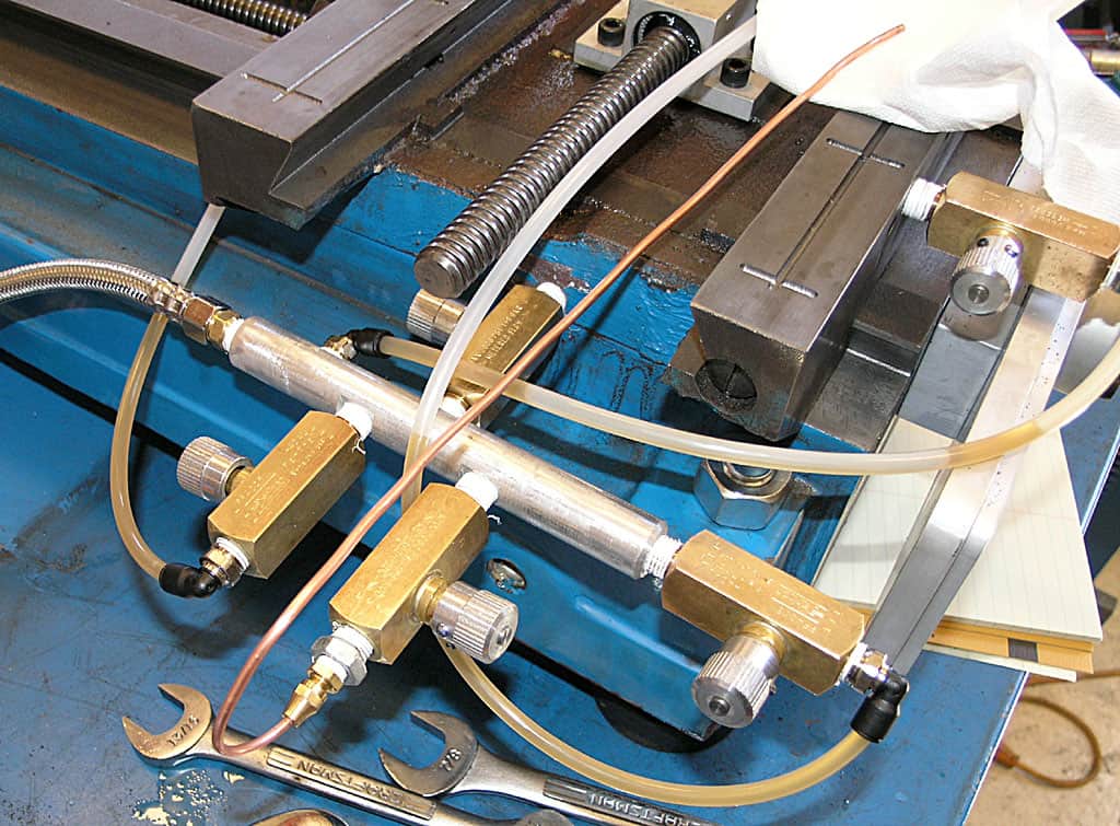
Clear tubing makes it easier to monitor the oil. I adjusted valves until the oil was arriving everywhere at about the same time...
Between having lapped the ways and installed this one shot system, I can turn the ballscrews and motion is velvety smooth even when I've got the gibs as tight as they'll go with a screwdriver!
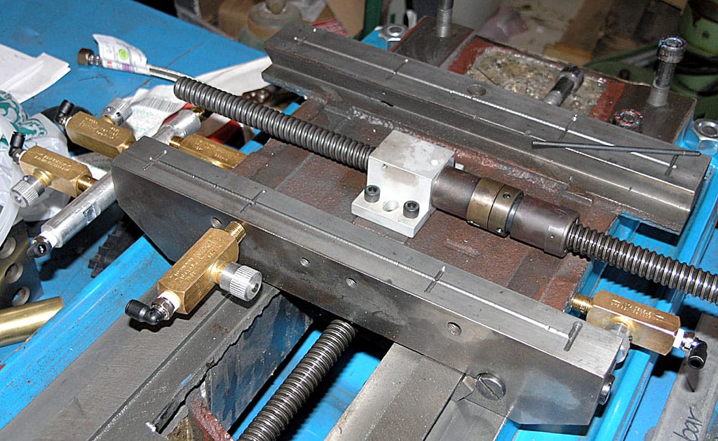
Oil Pump Mounting
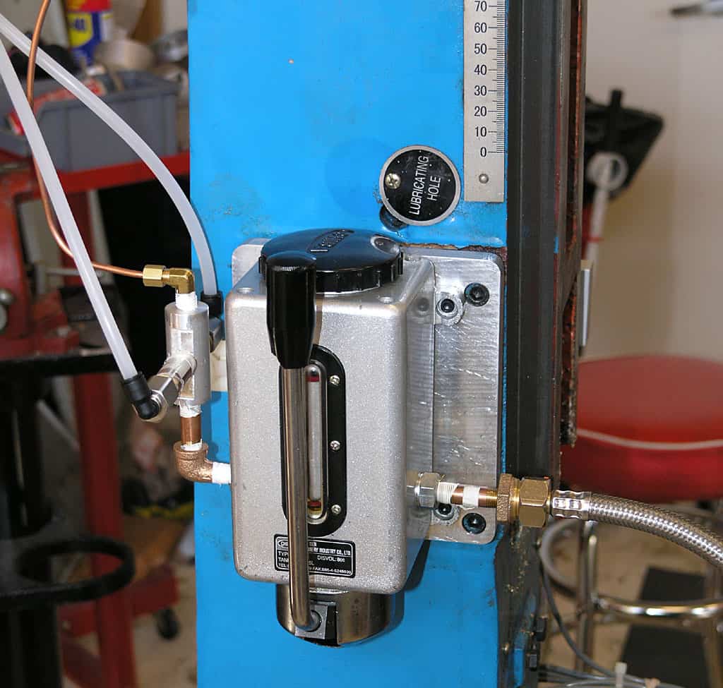
Here's what the finished pump mounting looks like. The front line goes to the saddle. The rear line goes to the little manifold which has a vinyl tubing connection for either way on the Z saddle and the copper tubing goes up to oil the ballscrew. The rear circuit would benefit from a flow control valve, but I ran out of fittings. The flow control valve has two benefits. First, the check valve would keep the line charged so there'd be no need to pump oil up so far. Second, the current circuit flows a little too freely relative to the other circuit, so I get a bit more oil on this circuit than I'd like. It isn't terrible, so I don't know if I'll fix it or not.
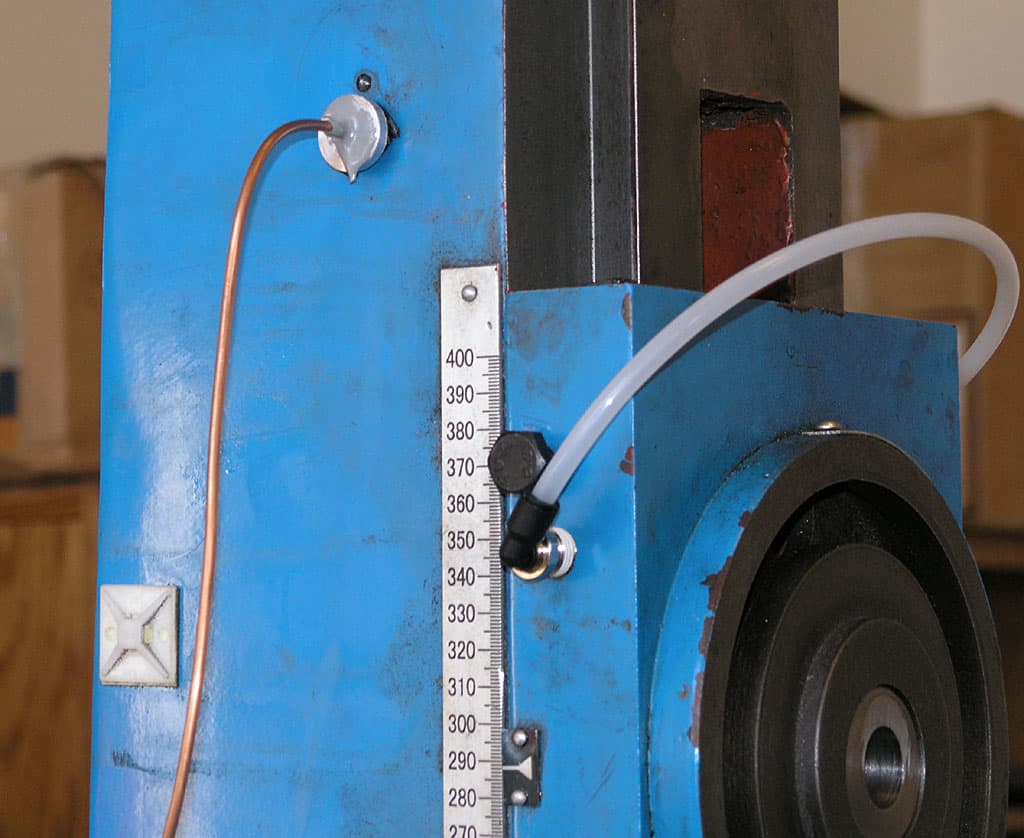
I reused the original oiling hole for the ballscrew oiling. I turned a little press fit piece of aluminum and JB welded the copper tubing into the proper position. The oil flows out onto the top of the ballscrew where it can drain down through the grooves all the way to the ballnut.
While a little change here or there might improve the system (for example, a flow control on the Z-axis circuit), I am calling the one shot oiler done. It works extremely well and will give me a lot of peace of mind about the mill's durability and proper oiling. It was well worth the amount of effort I've invested in the project.
Other DIY One Shot Oiler Projects
This modification has been done by Thomas Powell on his IH mill.
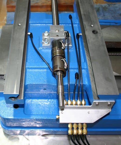
It's all mounted on the saddle. Lines into saddle feed Y-axis ways, X-axis ways, and X-axis ballscrew. The 4 lines going the opposite way feed the Z-axis ways, Z-axis ballscrew, and Y-axis ballscrew. Oil comes in via the heavy black hose from the pump...
Thomas mentions he wishes he had cut some oil channels into the ways. Now that I own 2 IH mills, I can use one to cut the grooves in the other with a small ball mill. If I didn't have a second mill and was desperate to have some grooves in the ways, I guess I would try to design a fixture that slid along the ways with a high speed spindle and stone attached to do the job. The other thought is to just run a little CNC program that moves the machine axes to spread the oil while the pump lever is pulled a few times. This would be a "warm up" sequence for the machine to run at the beginning of each session.
The consensus seems to be that 1/4" tubing will work well for this sort of thing. If the tubing doesn't move, some folks like to use stainless tubing.
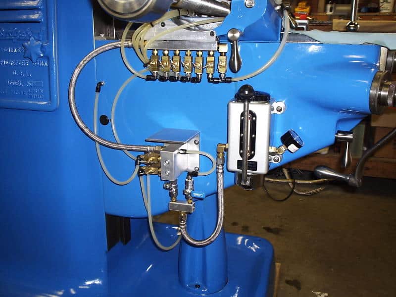
Mxtras one shot lube system on his Bridgeport...
Thoughts:
- One shot on a Bridgeport: He used Bijur B1114 metering valves, an 8 port manifold bought from Enco, and 1/4" tubing (some stainless, some flexible plastic).
- Nice thread on one shot systems on CNC Zone.
- One shot lube system on Bridgeports.
- Mxtras one shot system on a Bridgeport.
- Kay Fisher does a one shot system on a Bridgeport
Mxtras and others like Thomas Powell have used Legris 3109 series push lock pneumatic fittings. Mxtras says that in retrospect, he wishes he had check valves, and suggests using air flow control valves, which have built in check valves. He is planning to fit Part #7065 56 11 (1/8"NPT, 1/4" tube) Legris quick connect flow control valves. McMaster-Carr lists flow control valves (62005K224), but they are $17 each!
The IH mill will need the following lube circuits:
X Axis: Left & Right Ways, Ballnut
Y Axis: Left & Right Ways, Ballnut
Z-Axis: Left & Right Ways, Ballnut
For a total of 9 circuits. In terms of fittings, this means 9 fittings to thread into the base castings, 9 check valves, and a manifold with associated piping. There will also need to be a couple of fittings and tubing to connect the pump to the manifold.
Be the first to know about updates at CNC Cookbook
Join our newsletter to get updates on what's next at CNC Cookbook.