DIY CNC Kit: RF-45 Milling Machine Conversion / Retrofit
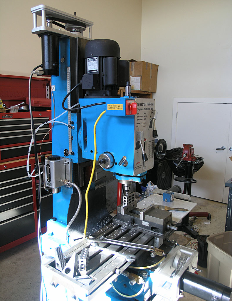
This page chronicles the DIY CNC conversion of my Industrial Hobbies RF-45 milling machine. It's written blog style, with the newest entries at the top. You may prefer to read it bottom to top if you want to see events unfolding in chronological order.
This project resulted in a potent CNC machine with many great features such as servos rather than steppers and a powered drawbar. It's biggest disadvantage was the gear-driven spindle which limited maximum rpms to quite a low number. Plans were underway to build a belt-driven spindle capable of much higher rpms but I wound up purchasing a Tormach PCNC 1100 instead.
I'd invested a huge amount of time into this project and wanted to get on with making parts rather than continue to build a CNC machine.

CNC Conversion Blog
5/23/10
Limit/Home Switch Noise
I recently got my Home Switches going and decided to go ahead and enable them to act as limit switches too. That's when I became aware of just how much noise there was on the lines. I was getting a gratuitous limit fault from noise about every 2 to 3 minutes. No worries, I did what I should have done to start and grounded the foil inside my cables to the CNC electronics cabinet via their connector. The noise went away immediately and life has been good since.
If you didn't think you had much noise in your system, maybe its because you didn't have a way to check? Ground the cables at the electronics cabinet end (not the machine end, that can create ground loops).
Mach3 Users: Make all of your Accelerations the Same on your Axes!
I discovered this was a problem while making my tapping arms. Due to the high rate of feed (50 IPM) and some abrupt changes of direction to follow the profile, I hadn't really encountered the problem before. I had heard on one individual having an issue with wildly different motor tuning on a knee versus his X and Y axis. It had been said this was a bug in Mach.
In any event, as I discovered early in my machining of the axis arms, it isn't a good idea to have different accelerations on two axes. I wouldn't have noticed it had it not been for easing back the accel on the X axis because it was faulting too much when I run with two 6" vises on the table. I lowered the X axis accel to match the Z and forgot about it. This latest job making a tapping arm reminded me in short order that something needed tending to.
It seems odd to me that Mach3 doesn't account for this, and it ought to be classified as a bug. Mach's trajectory planner should be able to properly choreograph a coordinated move across n-axes with a different acceleration and top velocity on each. If nothing else, the lazy algorithm would simply limit all the coordinated axes to the least acceleration and velocity of any axis involved at the time.
In any event, if you think you're doing yourself a favor by finding each axis's maximum performance envelope, you might in fact be doing the opposite until Mach learns to deal with it better.
BTW, the symptom will be that the tool follows the coordinated move's path in a very sloppy way. Going around the pivot point on the tapping arm swing block it was painfully obvious to the naked eye something was wrong-no calipers or micrometers needed.
5/1/10
Finally: Home and Limit Switches
Full details on the Home Switch page.
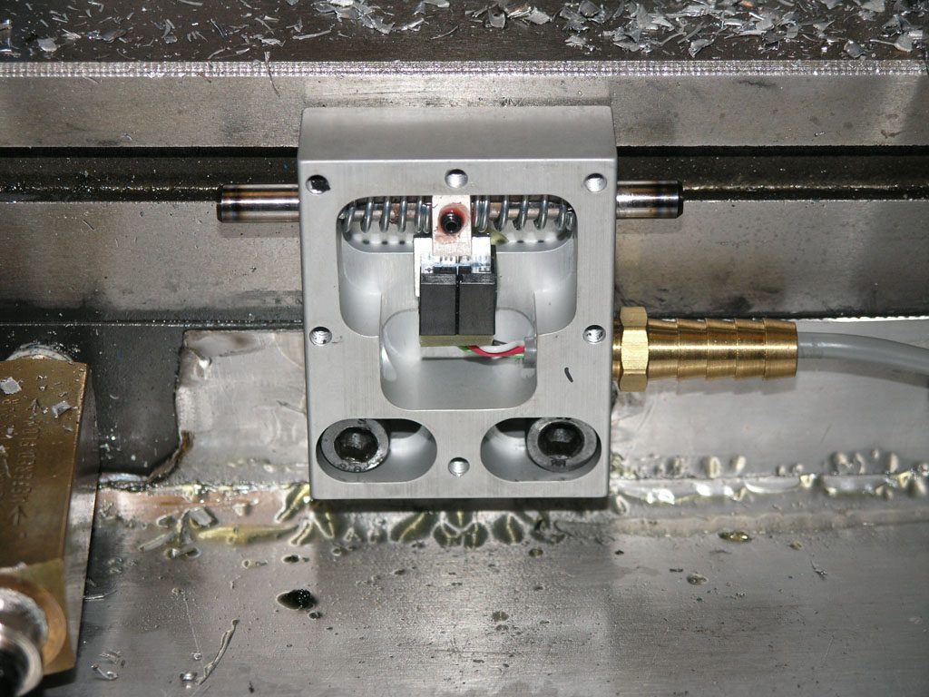
The X-Switch with cover off so you can see how it works...
Machine Tuning as Preventative Maintenance
I like to fiddle a bit with my machines every now and again to make sure they're adjusted to tip top condition. The CNC mill seems to benefit from this the most. For example, the gibbs and sometimes the Mach3 motor tuning parameters benefit from periodic adjustment. Perhaps surprisingly, the tuning varies depending on conditions.
When its cold (like it is right now in my area), the mill is stiffer and seems to require lighter settings. When I load the table with two 6" Kurt vises there is enough weight to slow it down too. Right now I have the combination of both, so things are kind of "worst case", at least until I decide to throw a cylinder block up on the table and try to machine on that!
In addition, Z is the most sensitive (being the heaviest), followed by X, followed by Y.
So my current settings, which I regard as a worst case, are as follows:
X 110 IPM, 10 acceleration
Y 120 IPM, 15 acceleration
Z 110 IPM, 10 acceleration
I generally just leave Z right where it is. However, if the weather is warm and the table is lightly loaded, I may bump X up to 120 and 15.
It's concievable things can be made to run faster, but I like to keep my gibs very tight as well. BTW, they sometimes need readjusting too. The original owner of IH, Aaron Moss, once told me he retuned his gibbs every season. I can definitely believe that.
Something else that helps is a machine warmup. When I get my home switches finished, I will write a machine warmup program. The idea is to move the axes through their full range of travel for a period of time, and warm up the spindle bearings as well. This practice is common on full-sized VMC's, and there is no reason it wouldn't be helpful for my little mill too. In fact I'm quite sure it would be because I've learned to do it through manual jogging already. It would be even nicer to have a program run while I pump the oiler every so often to make sure plenty of way oil is being spread over all the surfaces.
5/30/09
Calling it Done!
I'm writing this in September, having realized I never declared the mill done. I just got busy making things with it. As near as I can tell, it was finished sometime in May. My last work involved trying to get it all dialed in to be as accurate as possible, one of the last aspects of that was squaring the column, so I'm going to use that as my reference for calling the job done.
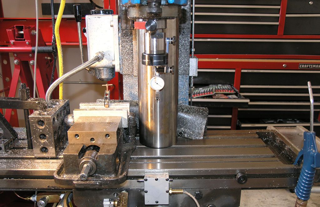
Squaring Your Mill Column
I squared my mill column a few weekends ago as part of an accurizing process I'm going through on the mill, but I only just took the pix off the camera and processed them today. I used a cylindrical square to measure how far off I was, leveled the table, and then shimmed the mill column to take care of the remaining error until I was just a few tenths off. The details are on my Mill Tips and Techniques page, but here is a teaser picture:
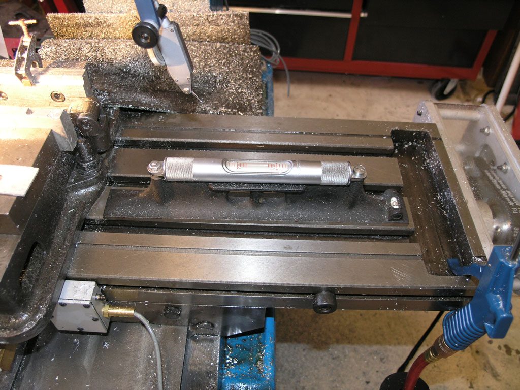
Leveling the table...
All right then, two teaser pix!
Even More Fun Stuff: Ballscrew Mapping With a DRO
I got my DRO installed on the X-axis of the mill and was able to do a little mapping action. Full details on my Mill Tuneup page, but here are some teaser pix:
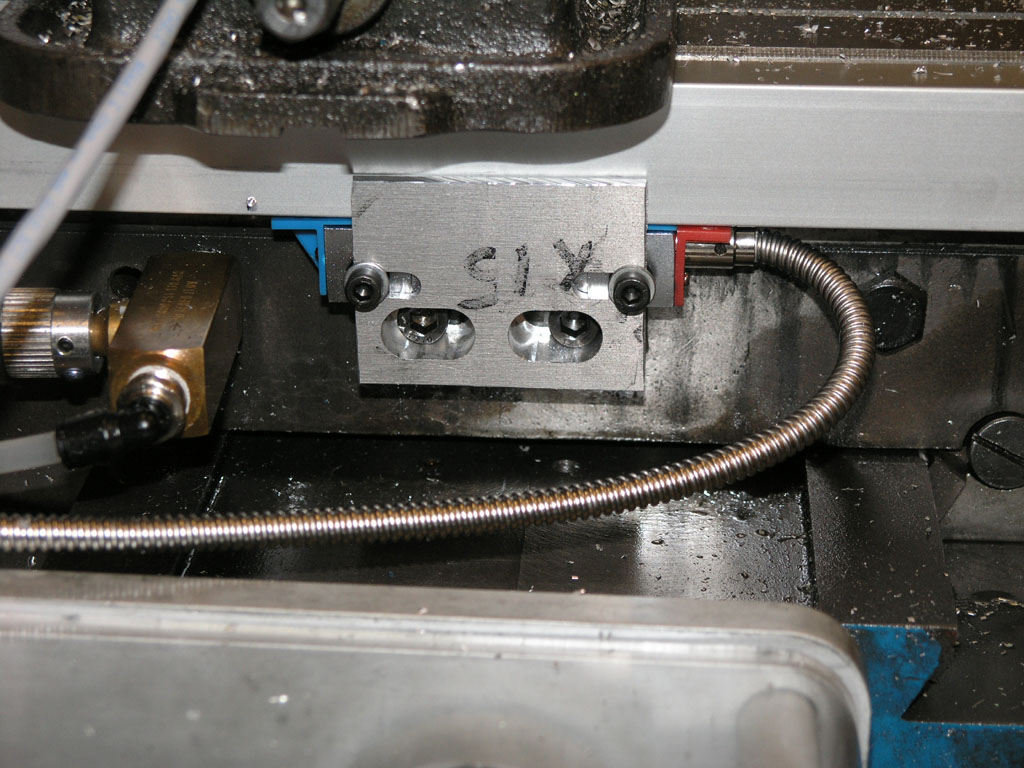
Reader head...
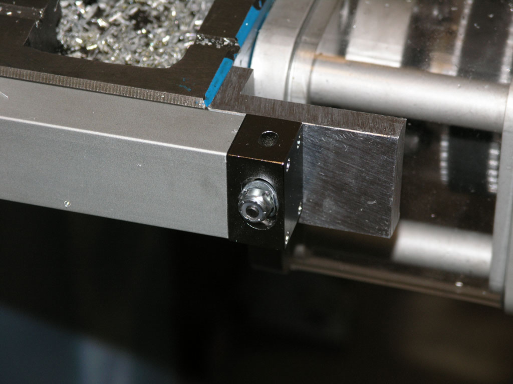
Scale mounting bracket...
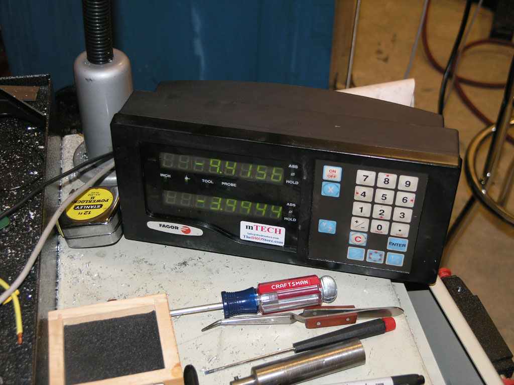
DRO control panel...

The error map for my X-axis ballscrew...
What can we tell from that error map?
The left axis shows the actual move of each commanded 0.5000" move as measured by the DRO. If the ballscrew were perfectly accurate, the graph would be a straight line centered on 0.5000".
You can see the righthand 40% of the ballscrew is qutie a bit more accurate than the left, although the first maybe 10% on the left is quite good too. Nevertheless, the whole screw moves to well under a thousandth of accuracy. You can also see that the errors are not cumulative, but are more periodic. The total error in 24 inches of motion was 5.6 thousandths and the screws are advertised as having less than 3 thou per 12", so this screw is within spec.
Mach 3 has the ability to take a map like that and correct for these errors. I haven't tried that yet, but it would be an entertaining experiment!
4/10/09
Getting My HEDS On Straight...
Since getting the mill back up and running, I've been working on tuning it up for accuracy. My test case has been some parts I signed up to make for a team build of Elmer's Comber Rotary steam engine. I've touched and tuned a lot of different things, and I'll write up the tuning process at some point as a coherent page. Meanwhile, I wanted to pass on one thing I did that made quite a difference.
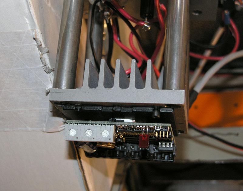
Mariss F. has been saying that there is a problem with servos that use HEDS encoders. These are the usual cheap US Digital encoders, and they're exactly what I have in my homeshopcnc servos. Some folks have said they had no problem with their encoders, others have said they have all kinds of problem. Mariss proposed a fix that involves some simple bypass capacitors, so I took it on myself to install the capacitors on my servos. Here is what it takes:
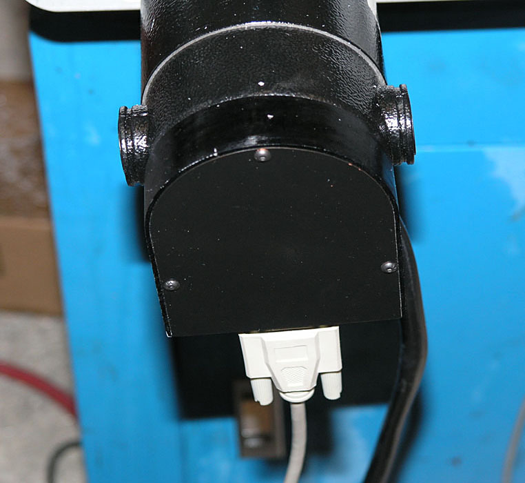
3 Allen-head bolts hold the rear cover on the servo...
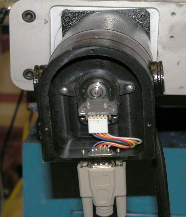
Here's what the innards look like. The HEDS encoder is connected by a simple little harness...
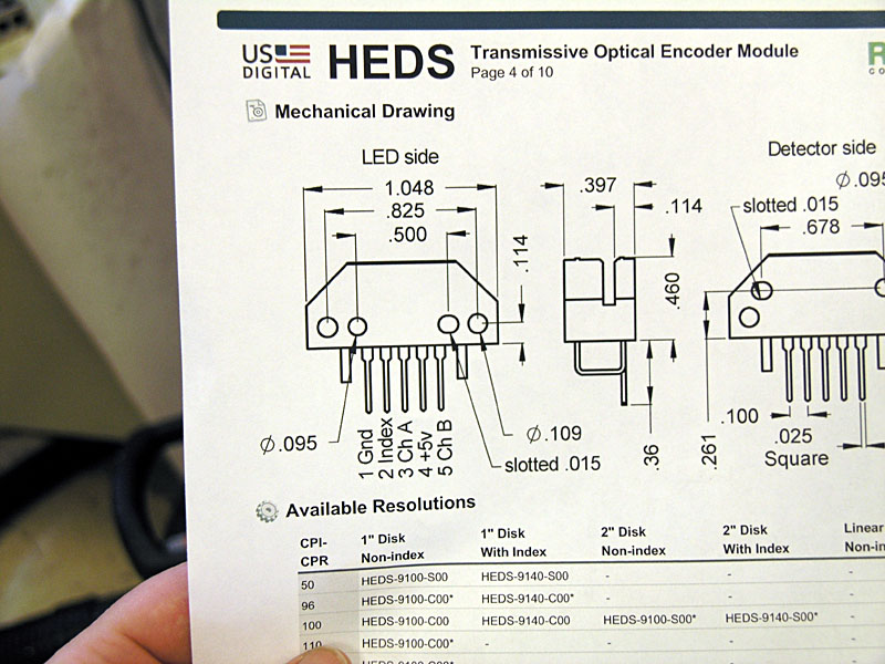
We're bypassing the power supply to filter out noise, so the capacitor goes between pins 1 (Gnd) and 4 (+5V)...
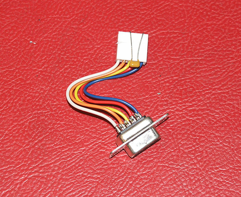
The easiest thing is just to bend the capacitor leads, insert into the connector, and then reinstall...
The ceramic 1uF capacitor goes across the HEDS power supply terminals at the encoder. Use Digikey BC1151CT-ND capacitors. They cost $1.80 for a package of 10 pieces and Digikey was happy to send them to me without requiring a minimum order.
The result? I immediately noticed my servos were quieter when not moving-less dithering. Some odd glitches and faults that would happen every now and again while jogging went away. Best of all, my part was suddenly being more accurately made-I was getting some false feedback from the encoder due to noise.
This is a quick and easy fix: highly recommended if you have HEDS encoders!
3/18/09
Finally, the Mill is Back Up and Running!
That power surge was really painful, but I finally got the mill running again on all 3 axes late last weekend. Turns out I had blown the Smoothstepper and 2 out of the 3 Geckodrives.
Having gotten the 2 drives and Smoothstepper replaced, the worst part was just figuring out what was wrong. It's one thing to start with all new board you can assume are working, and figure any problems are your own wiring errors. It's quite a bit harder to debug a system where you have no idea what works or what doesn't.
Having gotten the axes nominally going, my next task was to tune each axis. Servos have to be tuned. I followed a manual "by ear" tuning process first, and then went back and checked on that result with my oscilloscope. Full details are on my servo tuning page, but here are a few photos I snapped for your enjoyment:
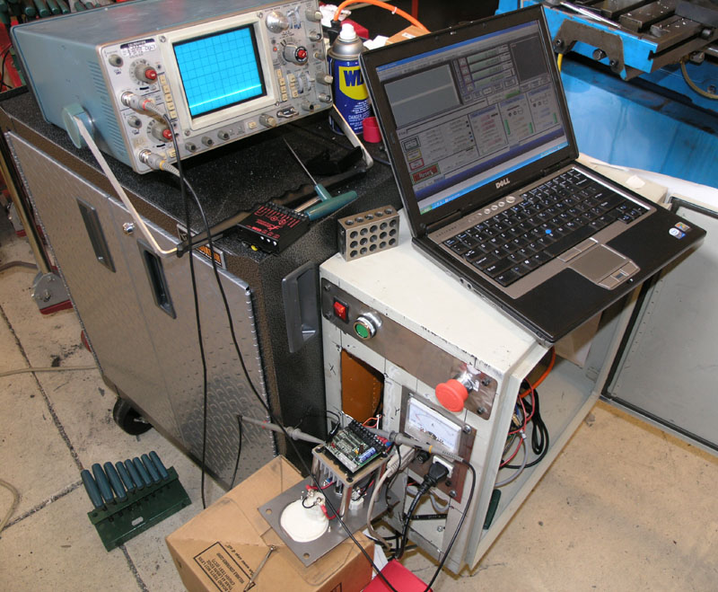
Oscilloscope is connected, but the axis isn't moving yet. I also haven't set everything up or you wouldn't see that trace without a moving axis!
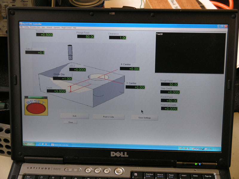
I use the circle pocket wizard's g-code for servo tuning. Set a small diameter circle and a relatively high feed rate and you'll get lots of direction reversals to use for tuning...
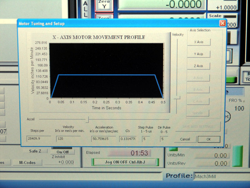
I got my mill X and Y axes up to 50 in/sec/sec or 0.13g's acceleration with the o-scope. Without it, I could only get to maybe 40'ish by ear. Z has the heavy mill head, so about half this much acceleration is available...
The X-axis right after o-scope tuning. Full clockwise current, nearly full gain, a little bit less damping. Your tuning settings will definitely be something different!
I did not get a chance yet to see what kind of rapids are possible. My tuning was focused on acceleration as it is a more difficult (and many advise more useful) performance characteristic to optimize. I was pretty happy with the results, but I intend to "detune" (back off slightly) in order to provide a margin for error.
2/22/09
Tough Week for CNC Electronics: Smoothstepper Lost to Storm
Man, it has been a tough week. I wanted to do some more chip cutting this weekend. Seems we had a big storm and it blew the power all over town. I didn't think much of it, and I was not even running the CNC machine at the time. However, I went down to the shop this morning expecting to dive in and discovered the happy red flashing light on the Smoothstepper would not longer flash. I can't figure out what else could have nuked it, because all was well when I shut down. Looks like I should have unplugged the unit entirely for the storm.
I have a new Smoothstepper on order. Man, these little electronics failures are not cheap!
Being desperate to do some work in the shop, but not having the working mill, I decided to mount the VFD in its NEMA enclosure:
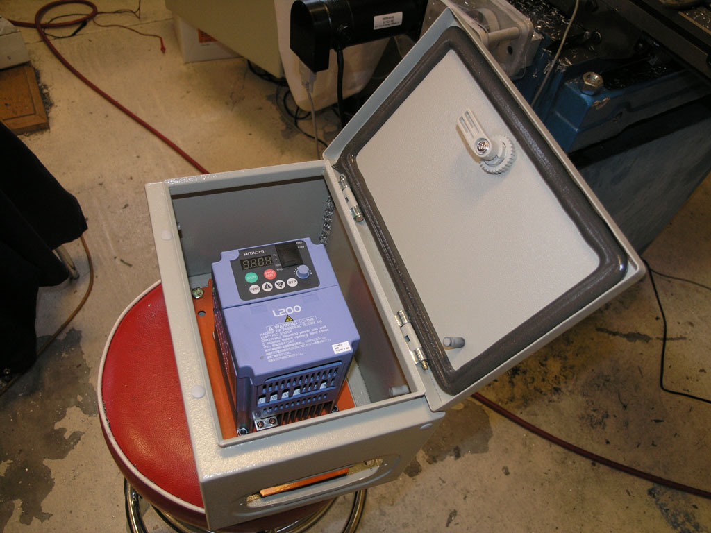
I'll be wanting to control the spindle via Mach3 soon, and I'll also want to mount my more powerful and faster motor, so this was a good move. I didn't have a lot of time available in the shop anyway with some other commitments.
2/17/09
Blew Up a Geckodrive
I started out tonight after work to make some more chips. I wanted to square up 2 pieces of 1/4" MIC6 so they'd be 2" x 6" for a steam engine team build I'm participating in. I discovered the Z was faulting off and on so I decided to crank up the tuning on all 3 axes. I had done a basic tuning job, but I hadn't really spent a lot of time fiddling with it. The mill head is very heavy, so I wanted to be sure it was really tuned up well to stop the faulting. I knew I had a tuning problem because it was only faulting when I wanted to raise the head, and then only when I did so rapidly. I turned down the acceleration a bit, and that was happier, but I'd still get a fault every now and then.
So, I decided to redo the servos. I got out my screwdriver and started tuning. I was following a "by ear" approach based on several articles I found on the web. In general, I did the following:
1. Start with gain and damping turned all the way down.
2. Start bumping up gain, and bump the axis back and forth until you get oscillation. You'll know when you get it, it can be pretty strong.
3. Increase the damping until the oscillation goes away and the servo is quiet. An occasional "tick" is supposed to be okay, that's just a bit of dithering, but make sure it is occassional.
This procedure was actually not all that hard, and before long I was ready to start machining again, or so I thought.
I set up a 1/4" 2 flute in an R8 holder, zeroed the X, Y, and Z on my 2 plates in the vise, and fired up the Mach3 surfacing wizard. It came back with some g-code it said would take about 12 minutes so I cut it loose, and sat back to watch. It seemed to be running along fine, but about 10 minutes into it, I got up off my stool and decided to go try to listen closely to each servo motor. I checked the Y, and it was good, but when I got to the X something looked odd. It sounded fine (hard to hear it clearly over the noise of the cutter), but the print on the timing belt looked slightly fuzzy. I decided I was seeing some oscillation and headed back to the controls to shut down. Before I could get there, poof! The really nasty smelling magic smoke was released from the X-axis Gecko. It had been oscillation and it had burnt up the servodrive.
Doh!
I shut down, went upstairs, and ordered 2 new Gecko 320's via 2nd day air. I was determined to make some real chips this coming weekend!
Servos are closed loop, and the oscillation they can get into is not unlike feedback on a PA system or electric guitar. Left unchecked, it can cause problems. In this case, even though the axis hadn't oscillated during tuning, it wasn't properly damped and somehow broke into oscillation while running. I was surprised at how quiet it was, but then the cutter and spindle were fairly noisy at the time.
Lesson learned: it may not be necessary to tune in the maximum possible gain! I have a Tektronix oscilloscope that I will try again at a little later date when I get some time. Meanwhile, I will manually tune a bit less aggressively.
2/15/09
Cut First Chips Under CNC Control!
Towards the end of this weekend I got the machine all back together and was able to cut my first chips under CNC control. Exciting stuff!
I spent quite a lot of time on what appears to be a dead motor. I took it apart and tested the capacitors. Looked like a bad starting cap. So I found another starting cap and tried that. Still nothing but a buzz when I flicked it on. At that point I was too eager to get going, so I just swapped the motor off the manual mill onto the CNC mill. Nice to have that extra mill!
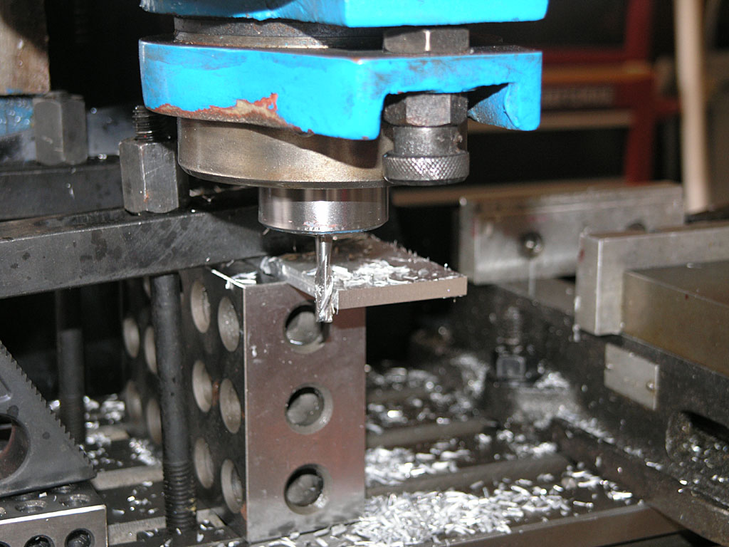
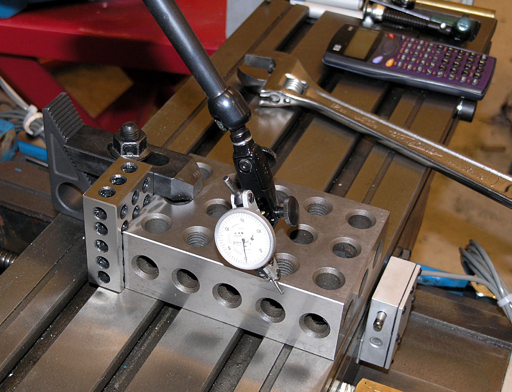
I spent a little bit of time calibrating the Z-axis travel (I had already gotten X and Y calibrated earlier) using a 1-2-3 block and my Z-axis touchsetter:
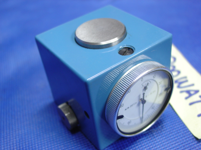
Z-Axis Presetter: When the needle is on zero the cutter is exactly 2.500" above whatever the presetter is sitting on. Yep, I got it from 800watt on eBay...
There is the mill in all its glory. Sun is setting Sunday night, so we need to get this show on the road!
I also tried a "touch off" with paper between the 1-2-3 block and the cutter. I like the Z-axis presetter better...
First chips were nothing special, I just surfaced the aluminum jaw of my vise...
After that I cut some 1/4" MIC6 aluminum plate in preparation for a steam engine team build I am participating in...
Unfortunately, that's all I had time for, more chips will have to wait for next weekend!
2/9/09
Dinked Around Modifying the Spindle Mounting Bolts
I spent about 40 minutes in the shop dinking around with the square head bolts I got from McMaster Carr. I ordered 3 3" long 5/8" 11 TPI square head bolts. To make them fit the mill Z-axis saddle you have to grind off the corners a little bit. 3" bolts are also a tad too long. With the bolts in the saddle I measure that I needed to shorten the bolts about 5/8" for a comfortable clearance. That would mean that 2 1/2" bolts might have worked out okay.
2/8/09
Calibrating My Axis Steps per Inch and Checking the Backlash on the Mill
I had an electrician come by, so I now have 220 for the mill (and a big compressor and a few extra outlets for other things). The next logical step is to mount the spindle head, but i'm stuck until I get some parts I ordered from McMaster-Carr. I need the square head bolts needed to secure the spindle to the Z-axis. They got misplaced somehow from the box of parts that came with the mill. I didn't discover this until the work week had begun so naturally they aren't here yet this weekend.
So, I was casting about for something else to do on the mill in the meanwhile, and I decide to calibrate the X and Y axis. This is not too hard to do and makes a big difference for the accuracy of the mill.
I followed this procedure:
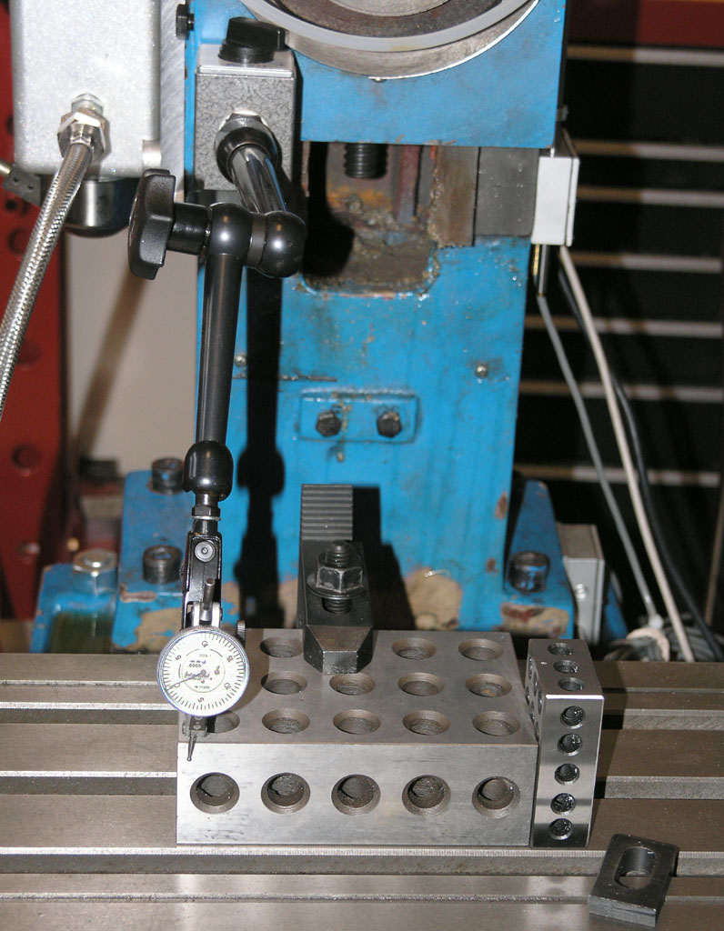
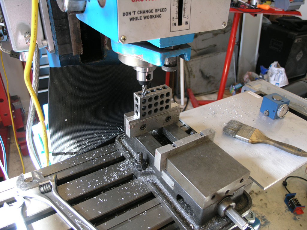
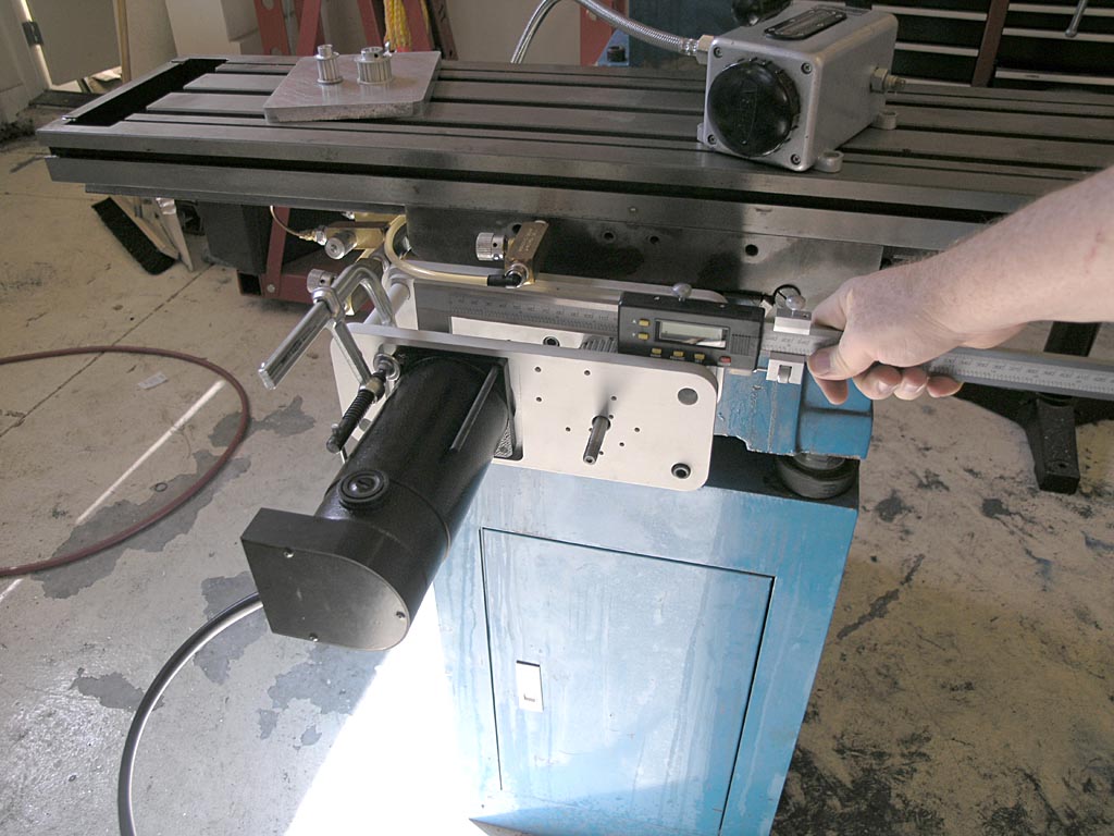
First I trammed in a 2-4-6 block so that the back edge was exactly parallel to the travel of the X-axis...
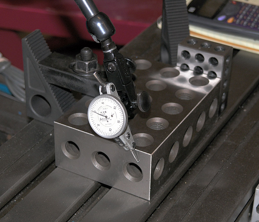
Here I am picking up the starting point. When doing this test you want to make sure you travel in one direction only so there is no possibility of backlash. If you change directions accidently, you have to start over. I jogged slowly up to the indicator until the needle registered about half a turn, then I zeroed the indicator...
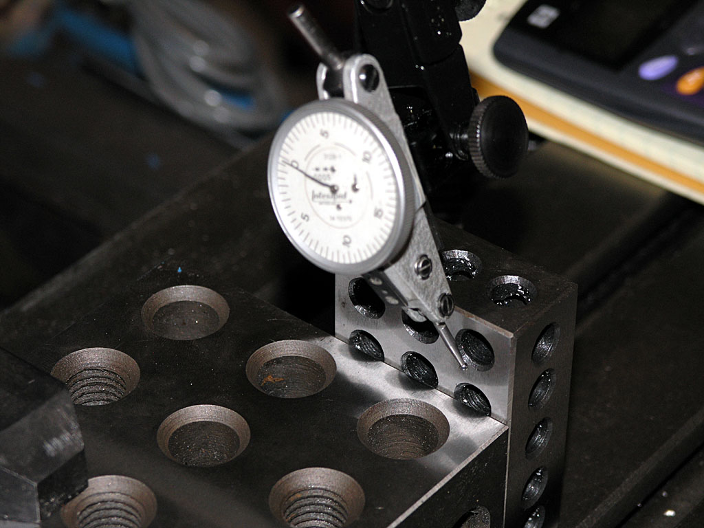
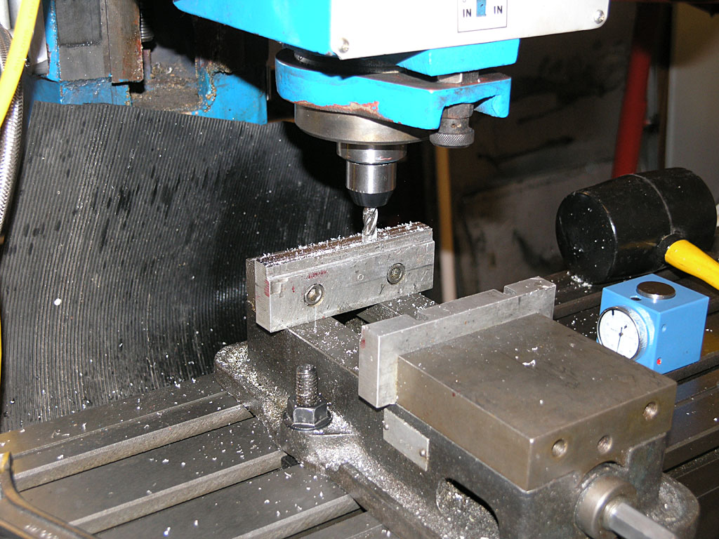
Then I jogged, being careful to move entirely in one direction until the indicator registered zero against the 1-2-3 block I'm using as a back stop. In Mach3 you can job in thousandths or tenths. Try that with your handwheels!
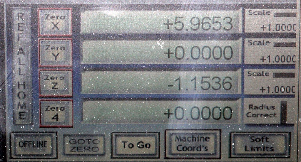
Now read the distance off the Mach3 X-axis DRO and compare it to the actual length of your 2-4-6 block. Mine turned out to be 6.0014" long. The X distance travelled was 5.9653" according to the DRO. The difference between the two tells me how much I need to increase my steps per inch with a simple ratio calculation. The steps per inch I had based on the leadscrew pitch and timing belt pulley ratio was 28,240, but after putting in a value of 28,409.9 and trying again it came out exactly right!
Here I am tramming in to do the same thing on the Y-axis. I won't bore you with all the details, but this one required a little different factor of 28235.8 steps per inch. Note that in theory X and Y should have been identical. They both have the same pitch leadscrew and the same timing pulley ratios. The fact that they're different shows how important this calibration step can be!
Next I measured my backlash on both axes. This is easy. Job up to the 1-2-3 block until the indicator ticks. Zero the indicator and the DRO for that axis. Back off an inch and then jog back in until the indicator zeros. Whatever the DRO reads is you backlash.
I got 0.0003" for the Y-axis and 0.0006" for the X-axis. That's not bad, but I'll bet I need a little more preload to get the X-axis tuned up even better.
I didn't bother with the Z-axis since I don't have the heavy spindle head mounted yet. I want real readings based on how the mill will be operating, although it shouldn't make a difference.
2/1/09
Newsflash: All Three Axes Are Running!
I made an adapter for the servo shaft and got the Z-axis running today. Minor tuning was needed, but the Z runs pretty smoothly.
Not a lot left to be cutting chips:
- - Mount the mill spindle head.
- - Get 220V over to it (easier said than done!).
- - Tune the servos for real.
- - Get out the dial indicators and get everything calibrates: steps per inch, backlash, squaring the mill, etc.
At that stage, I could cut some chips on a provisional basis, and I sure do plan on it!
1/31/09
X and Y Axis are Alive! Plus, New Servo Page
Between the wee hours Friday night and the morning today I've gotten the X and Y axis servos mounted and running. The servos are really not tuned yet, but even in their rough state I was able to move the table at 180 IPM! I am not suggesting that is something that will be accurate or even usable, it was just play, but it was fun! I tried for 200 IPM, but the servos started faulting again and I didn't want to spend too much time tuning for a scenario that isn't real anyway.
Meanwhile, I added a new page that gathers up all the stuff I had to do to adapt the HomeshopCNC servos to the IH Mill CNC Kit.
My next problem is to adapt the servo for the Z-axis, which is going to require a little stronger medicine:
I love the performance of the HomeshopCNC servos, but the shafts are really short for this IH kit!
1/30/09
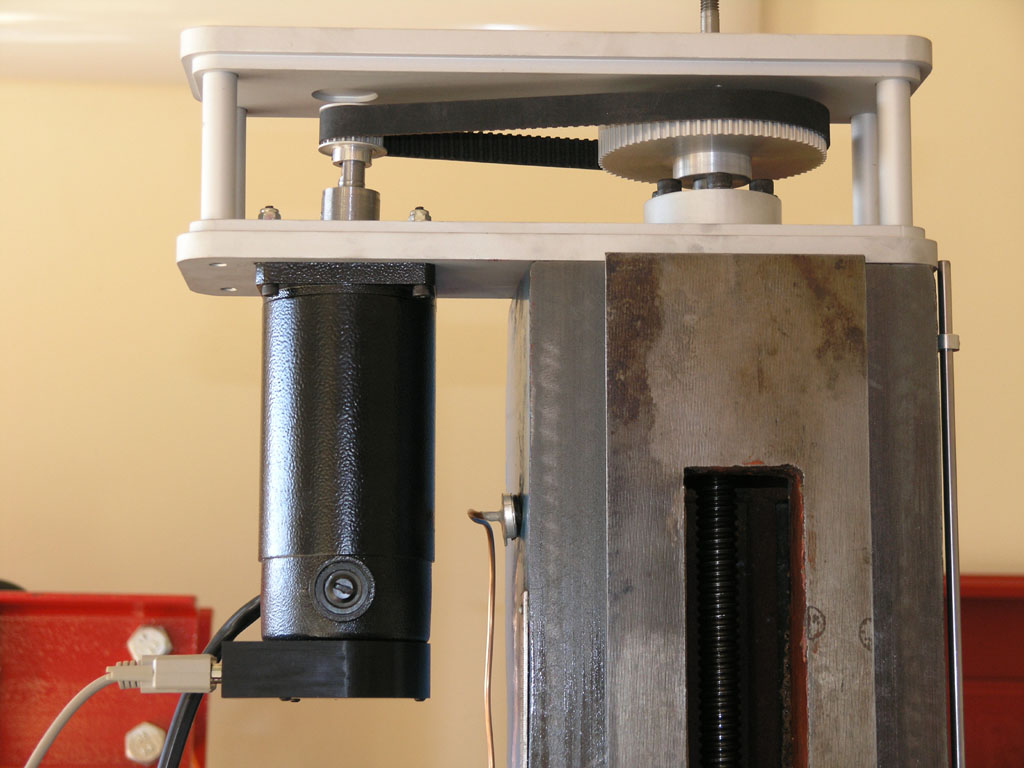
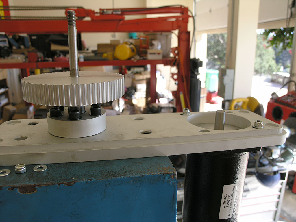
Mounting Timing Pulleys on the Servo
I'm going to use 1/8" roll pins to mount the timing pulleys to the servos. This is the method Gene told me is used by Industrial Hobbies on their turnkey systems, and it will provide a very solid mounting-much more so than a couple of set screws.
Here is where the hole needs to go on the X and Y axes when the timing pulley is oriented properly to mesh up with the pulley on the ballscrew:
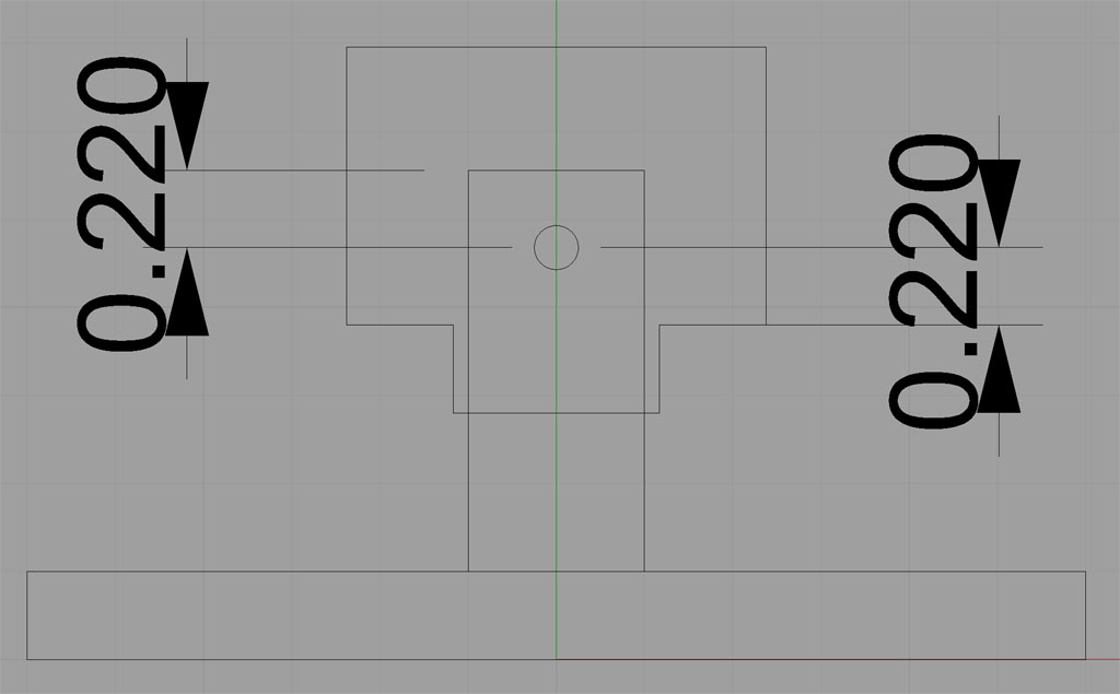
I can use the shoulder of the pulley and the end of the motor shaft as my datum reference points. I need an identical offset of 0.220" from either point to locate the hole in the shaft and the pulley.
1/29/09
Before I Forget: IH Limit Switch Wiring
I spent an hour and a half tracking this down just now on CNCZone. Here is how the IH optical limits are supposed to be wired to a breakout board:
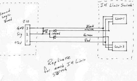
This schematic calls for a 270 ohm resistor, but another fella on the thread found a 330 worked better.
1/25/09
Lots of Fabrication, Wiring, Testing, and Diagnosing Went on This Weekend. Result? 3 Servos a-Spinning!
My goal for this weekend was to have the enclosure mounted on the rolling tool cabinet and be able to spin all three servo motors. Easier said than done!
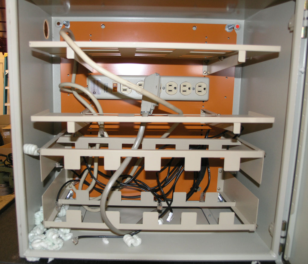
Mounting the enclosure was pretty easy, as was installing the electronics and axis modules. Here are some shots of how things looked just now when I was downstairs in the garage:
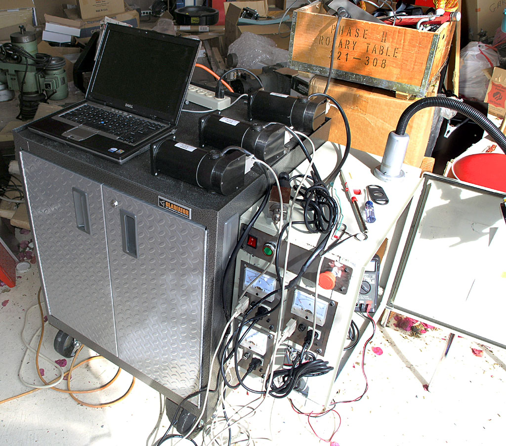
Messy! It sure is nice that I can use a laptop with the Smoothstepepr...
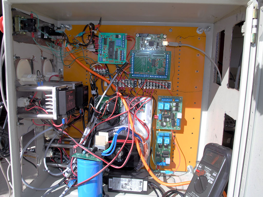
Very messy wiring. After I get everything working, I'll be milling new panels (using this CNC mill of course) and I'll take that opportunity to build some real wiring harnesses that clean this up!
The wiring is pretty messy, but I'll be rejiggering it to make some real wiring harnesses and clean it up on a future pass. Right now I just want to make it work. Most of my difficulties have been with the C17 card and getting it to reliably deal with servo faults. I haven't yet decided whether the board is flaky, or whether I'm just using it wrong. I do know I have seen it do some pretty odd things. When I got everything into this cabinet, for example, it completely quit closing the relay during the startup sequence. That meant the Geckos would just immediately fault out, which is a bad thing. If you read my diagnosis page, you'll see I keep having this problem over and over. Each time the fix is a little different. This time I got things going again by connecting the switched side of the Start button to the DC supply relay. That ensures it gets closed during the Start cycle regardless of what the C17 chooses to do. As is usual for me, I didn't think of this solution until after I'd slept overnight from a frustrating earlier session.
Now I've got all 3 servos spinning. X tends to fault out, but that's just because I don't have the servos in a very good state of tune. There's liittle point in it until I can get them mounted on the machine anyway because they'll just need returning. Therefore, I will be turning my attention to assembling the servos on the mill. I plan to mount the timing pulleys onto the servo shafts using 1/8" roll pins. This is how IH does it on their turnkey systems and it'll be a lot more solid than trying to use setscrews on the powerful motors I've got. Towards that end, I was researching the proper hole sizes to drill and came across a page from SDP-SI on it here.
It's been a busy, but fruitfull weekend!
1/12/09
Axis Modules Are Done Pending 2 Cables
All three axis modules are now assembled and tested. As I was finalizing the last of the three modules, I decided I wanted a quick disconnect on the signal wires, so I made up a cable out of a male and female DB9, and that looks like it will work well. I just need to make 2 more of those cables for use with the other 2 axis modules.
Here is what a finished module looks like with the quick disconnect:
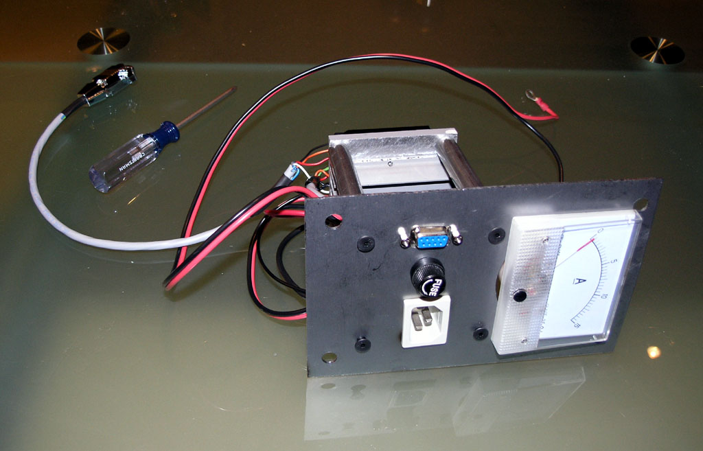
To install an axis module in the enclosure requires 2 connections-the quick connect is all the signal level stuff, and then there are the main DC power supply + and - that go to bus bars. It should be pretty quick and easy to install one or switch one with another to clear up some issue. I could've skipped the quick connect, but I got to thinking about poking and prodding inside that enclosure on my hands and knees and wanted to make it easier.
What's next?
1. I need to finish making the other 2 quick connect cables. That'll be easy to do during the week, I hope.
2. I need to clean up the enclosure itself, get it mounted on the side of the rolling chest, and get the electronics mounted inside and tested.
3. Last step is I need to install the servos on the mill and then see the axes move.
We're getting closer!
1/3/09
Major Milestone: Spinning a Servo! (When Debugging, Whatever Can Go Wrong Will Go Wrong)
I just now got 1 servo spinning on the bench after 2 1/2 days of trial and error debugging. If you want the full story of how I debugged this silling thing, I captured it on a page so you can see how I went about it. It's a painful process as not all of the relevant information you will need is captured in one single place. Some of it was out there, but a lot of it I just had to figure out on my own.
Here is a concise list of all the things I had to change from my original attempt to run:
- Set CNC4PC Master Control Board DIP switches for G320. It acts funny on the other board types whether or not Err/Res is connected.
- Discovered I had mislabeled the leads from my front panel for the "Start" and "E-stop", so they were connected backwards.
- Reverse the motor connections because they were backwards compared to what the encoder indicated, causing an immediate servo fault.
- In doing #3, I reversed the wrong leads and had to replace the power supply rectifier. I don't think I blew the Gecko, amazingly!
- Connect a 47K ohm resistor across pins 1 and 3 of the G320 to ensure the bridge initializes properly. This was buried in a hard to find Mariss note on CNCZone
- Now I was getting the servo to hold position, so I played with the tuning trimpots a bit
- In Mach3, set Step/Dir to ActiveLo. Set pulse width to 5 (the pulse width may be ignored for Smoothstepper).
- Connect "Common" on G320 to +5V on breakout card instead of Ground. Another one that's easy to miss unless you read a lot of posts on various boards!
- Set up the proper motor tuning parameters on Mach3. IH says 115 IPM speed and 0.15g of acceleration, according to another post I found. I also needed 28,240 steps to move 1".
- Set the Smoothstepper jumpers to actually provide +5V to the breakout board. Otherwise, the terminals marked "+5V" are 0V!
Now I can spin the servo this way and that with Mach3. It can still fault if I rapidly change directions at full jog, but that's just tuning and I need to set it properly on the actual machine instead of with servos flopping around on the floor.
I must admit that per the discussion on the Cookbook Blog on the Eternal Servo vs Stepper Jihad, it was a lot harder to spin a servo than a stepper. In general, I encountered a lot of less than obvious things including the CNC4PC DIP switch settings, need for the 47K ohm resistor (that's going to be built into the next generation Gecko servo drives), and bizarre experiences with "Common", which has to be +5V, and which didn't get +5V until the Smoothstepper jumpers were enabled.
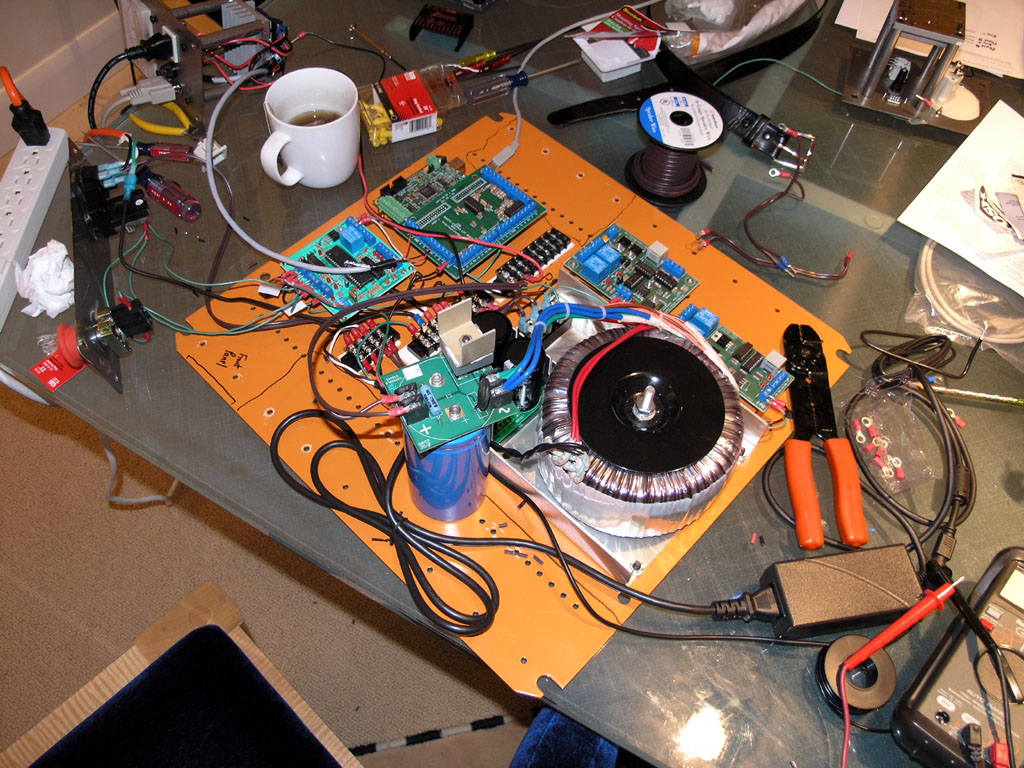
Here are some photos of my CNC electronics testing lab on the dining room table (my wife is glad it seems to be working and I'm cursing a lot less!):
Figuring Out Mach 3 Parameters for My Servos
I have 500 CPR encoders on my servos, which means 500 x 4 = 2000 steps per motor revolution. It takes 5 (leadscrew pitch) * 2.824 (timing belt ratio) rotations to move the X or Y axes 1". So, I need 2000 * 5 * 2.824 = 28,240 steps per inch of axis motion. IH runs at 100 IPM, so I'll set this maximum speed initially.
12/27/08
Wiring Continues, and Powder Coat is On Order
I have been busily making cables and wiring up the enclosure. There are a lot of connections here! I have my wiring diagram and I am coloring in each connection as I finish making it. Everything is point to point, so I am making little wiring harnesses and trying to keep it neat.
At the moment I'm just trying to get to the point where I can make one axis module active and spin a single servo motor. If that all works, I will assemble and test the other 2 axis modules. After that it will be time to finish up the enclosure. I got a neat powder coating kit from my brother for Christmas, and I just ordered some Ocean Blue powder coat from Caswell Plating. I think the Ocean Blue will match the IH mill blue pretty good. Powder coat is very durable. Not really necessary for this application, but I thought it would be fun to try it out!
12/21/08
Progress: Wiring Diagram, Board Mounting, et al
You can be forgiven if you don't think I've been doing anything for 3 weeks. Reallity is I've actually been pretty busy. It takes a ridiculous amount of research to figure out how to wire up one of these CNC projects right, so that's a big part of what I've been doing. Ordering various ancillary parts and mounting my various little sub-circuit boards to a big mounting plate that goes in the enclosure would be the other part. Today I got started wiring up. I want to do just enough wiring to verify I can spin one servo sitting on the bench before I do too much else.
Meanwhile, here are some tidbits:
Smoothstepper wiring (more detail on the electronics page):
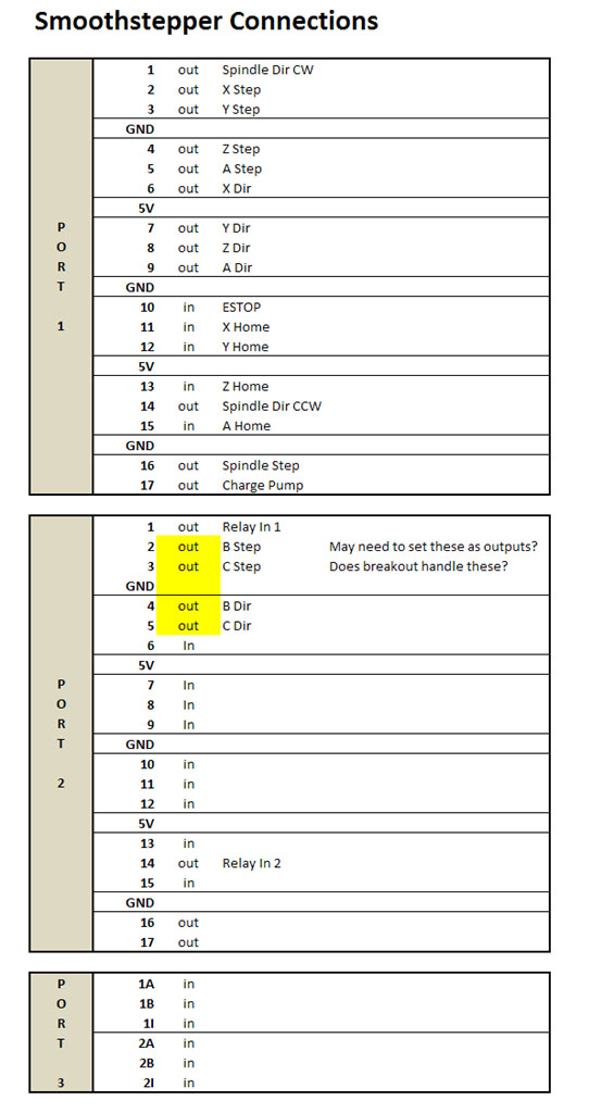
Compare this to the diagram directly below. Notice I am reversed. That's intentional, I decided to mount the NEMA enclosure on the side of the rolling cabinet that will be closest to the mill...
12/2/08
Getting Geared Up to Wire the Box
I've been getting in a plethora of odds and ends to start wiring up the enclosure. I've now got everything except a relay I will use for the E-stop circuit and the master AC on/off switch for the front panel. I also did a number of versions of the overall schematic. The latest is on the enclosure page. Based on my latest schematics, I've done a layout for how I'll go about mounting the various sub-boards in the enclosure:
My goal this weekend would be to get the enclosure to the point I can actually mount the boards and begin the wiring process next weekend, and hopefully try spinning some servos (though not on the machine) next weekend as well. There's quite a bit of work to do there, but if I get enough hours I should reach that stage. Fingers crossed!
I still need to make an arm to support the keyboard and monitor, I need to mount the enclosure to the rolling cabinet, and I also need to paint it.
There's still a lot of fussing. I haven't spec'd or ordered any of the auxilliary panel connectors, for example. I have some sitting around the parts bin that will hopefully work. Have to look at them as well. If need be, I can delay VFD and coolant wiring until after the servos are running and it would be no big deal.
11/23/08
New VFD & Spindle Control Page
After spending a couple of hours last night and this morning studying my VFD and controller board, I wanted to start a new page for the VFD work. The work required to control the mill spindle from Mach3 is not terribly hard, but there are a lot of details, so I've split it off to a different page to make it easier to follow this subsystem.
11/22/08
2 Hours of Progress this Morning
Two hours this morning, and while I did a lot of different things, it doesn't feel like all that much progress. Doh!
I started out with my new treppaning hole cutter from SPI. I've had so much trouble make large holes in metal sheet over the years I finally sprung for a professional tool. I started out trying to finish the meter hole on the 3rd axis module. Things got off to a good start and then got progressively worse until the little tool snapped clean off! Fer cryin' out loud!
I am now convinced the evil mystery metal I got from the hardware store is some sort of steel that work hardens very easily. I can find no other explanation for how difficult it is to work with. In any event, before it broke the cutter almost got through, so I knocked the disk out with a ball peen hammer. I need to clean up part of the hole with an abrasive grinder of some sort, but it'll be fine.
I turned from that to mounting the Antek power supply in the enclosure box. That was no big deal: set supply in position, mark holes, drill holes, done! So that's ready to go when it's time. I'll leave the supply out of the box for the time being because there is still more cutting and drilling to do there.
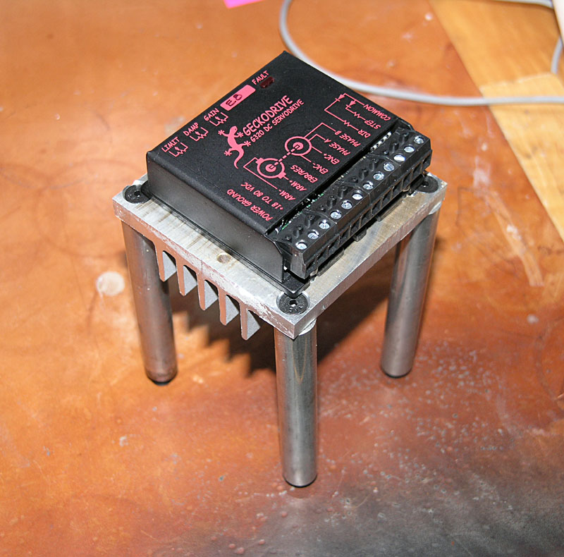
Next I turned my attention to the 8 standoffs used to mount the Gecko drive and heatsink to the axis module panel. These 8 had not yet had holes drilled and tapped in either end. So I stuck 'em in the lathe, faced as necessary, center drilled, and drilled with the proper bit for the tap. When all 8 were done, I went over to the mill and power tapped each hole with a spiral flute tap.
That's two hours of my morning and now it's lunch time. Nothing worth taking a picture of even.
11/15/08
Got Most of the Cutouts in the NEMA Enclosure
I will still need holes for the cooling fan, but I want to make sure I understand the clearances and location of everything else before I try to position the fan. My current thinking is to put it in the door next to the hinge and up high to exhaust the warm air. Wish I had a louver punch!
Here are some piccys:
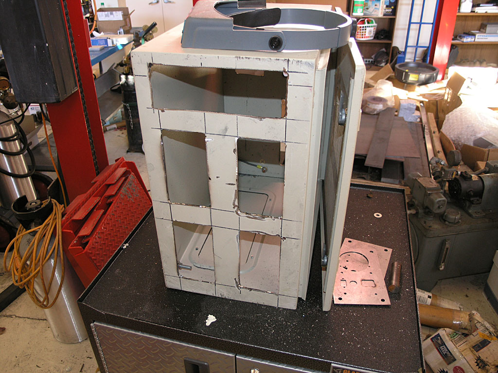
The panel inserts cover the holes. 4 axes on front, with a master control panel at the top. I could possibly also exhaust the fan at the right side of that control panel...
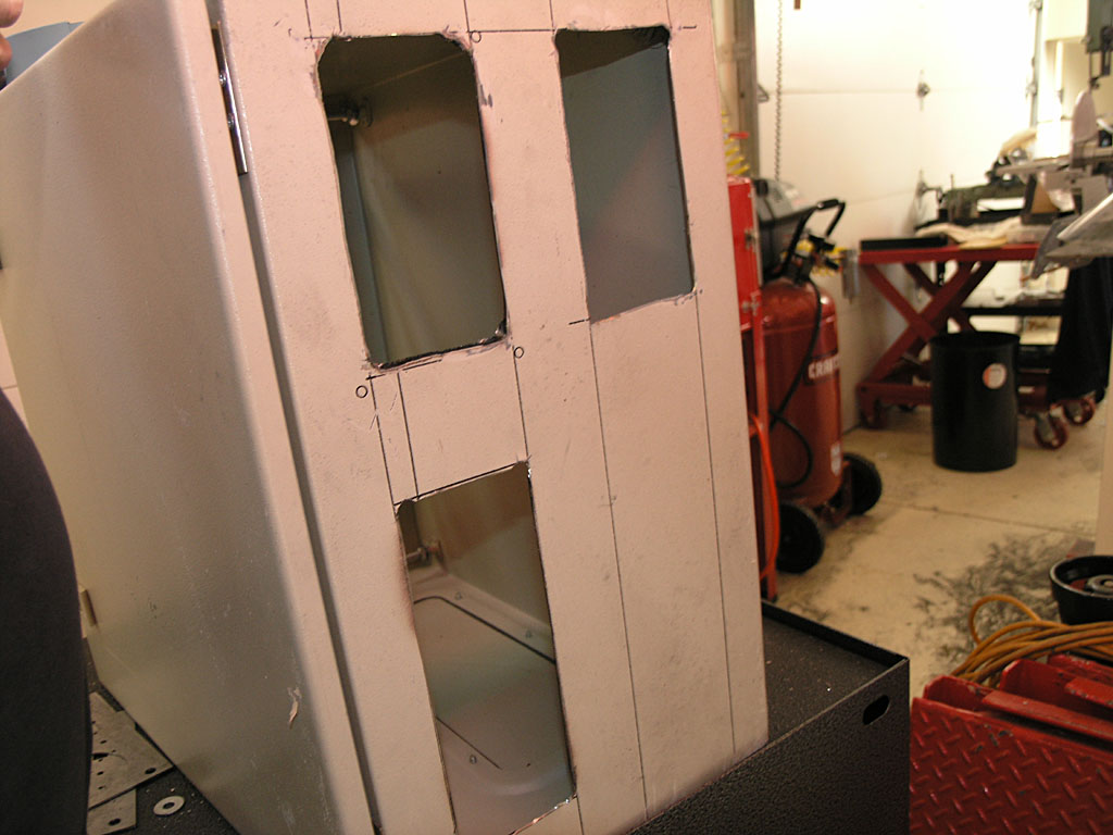
Three rear panel cutouts. Top 2 are for 2 more axes. Bottom will be for all the auxilliary connectors for limits, coolant relay control, and VFD control...
More detail on the enclosure page about how I did the cutouts.
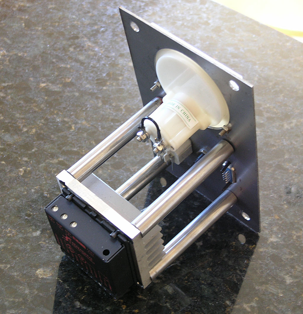
Some Progress on the Axis Modules
I've got one pretty well mocked up with all the parts mounted:
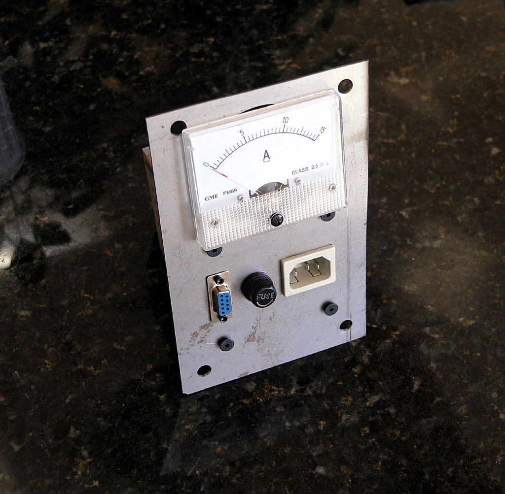
As you can see I have an issue with meter clearance and the mounting bolts, so I made an oversized hole to try to create some "wiggle room". This happened due to an error in laying out the big square face during the CAD design. What I need to do is relocate the whole meter 1/4" down the panel and all would be well.
I've gotten it close enough, I think. I can't go much further or I'll lose the mounting holes for the meter as you can see in this behind shot. In the end, I'm planning to remake these panels anyway once the CNC is up and running. I'll make them out of 1/4" aluminum plate and put some engraving and other decorative touches on so they'll look a lot nicer.
Soldered the Cables on the Servo Motors
The servo motors come from Homeshopcnc with just a short tail on them, so you'll need to attach a longer cable back to you electronics cabinet. I decided to use IES-style power cords for mine. These are the same power cables a PC uses. I chose them becaues they're cheap, the servo only has 3 conductors like a power cord, and they're designed to carry current. My one reservation would be that they're not shielded, so the noise from the servos will escape. That means I need to take care the rest of the cables, for example the limit switch and encoder cables, are properly shielded for noise and the shields are grounded.
I put 10 foot power cords from CableWholesale on the motors...
Homeshopcnc Servo Encoder Pinout
Got a note back from my query to Homeshopcnc on pinout for the encoders. They say the 5 pins on the encoder correspond to the top 5 pins on the DB connector. that pinout would be:
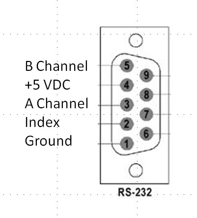
Also worth noting is that I have specified 500 CPR encoders on these servos. With quadrature, that means 2000 steps per revolution.
10/30/08
Miscellaneous Mill Progress Updates: Timing Belts, Martian War Machine Axis Modules, Limit Switches, and Sheet Metal Templates
Tonight was a productive evening in the shop!
I discovered some time back that the 72 tooth timing belts I ordered for the X and Y axes were too small. Doh! Turns out I made a minor miscalculation in the geometry involved. I was very concerened I would discover the timing pulleys I had ordered were also not going to work as you can only get belts in certain sizes. Fortunately, luck shined on me and I found that a 75 tooth belt works fine.
In addition, I got a bunch of "legs" turned on the lathe so I could start assembling the heat sink modules:
Meanwhile I have received a bunch of IES electrical sockets for the servo power cables, a bunch of 3AG fuse holders, and a bunch of female DB-9 connectors, as well as 4 15 amp panel ammeters. It's time to start thinking about the sheet metal panels. I picked up some 22 ga stainless sheet at Orchard Supply and I drew up a template in my CAD program:
About this time I got thinking about the one big round hole and the two square holes. Painful to make with my current equipment. I'll have to go buy a hole saw for the big round hole (for my load meter), and the squares have to be made by drilling out the corners as marked on my template and them milling or perhaps nibbling across to connect up the holes. All in all its a bit of a nuisance, and its got me thinking about punch and die work. I'd need 3 punches: one for the meter hole and 1 each for the DB-9 and IES power connector square holes. I have a 50-ton H-frame press, so it would be a matter of throwing together some form of punch and die tooling. Realistically, that's even more work than just making the panels the original way I had planned, but it sure is more interesting work. Gotta think about whether to go there or just git ‘er done!
Lastly, I got my Industrial Hobbies optical limits installed. They sure are cool. Here are some pix:
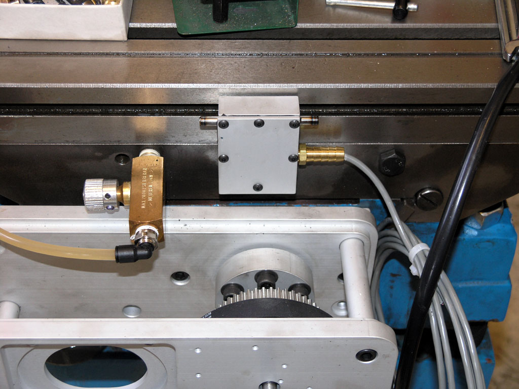
There is the X-axis limit. It installs in the existing 2 holes on the saddle and is triggered by the table stops in the side T-slot. As the IH directions suggested, you have to put a washer behind the table stops to keep them from wiggling around...
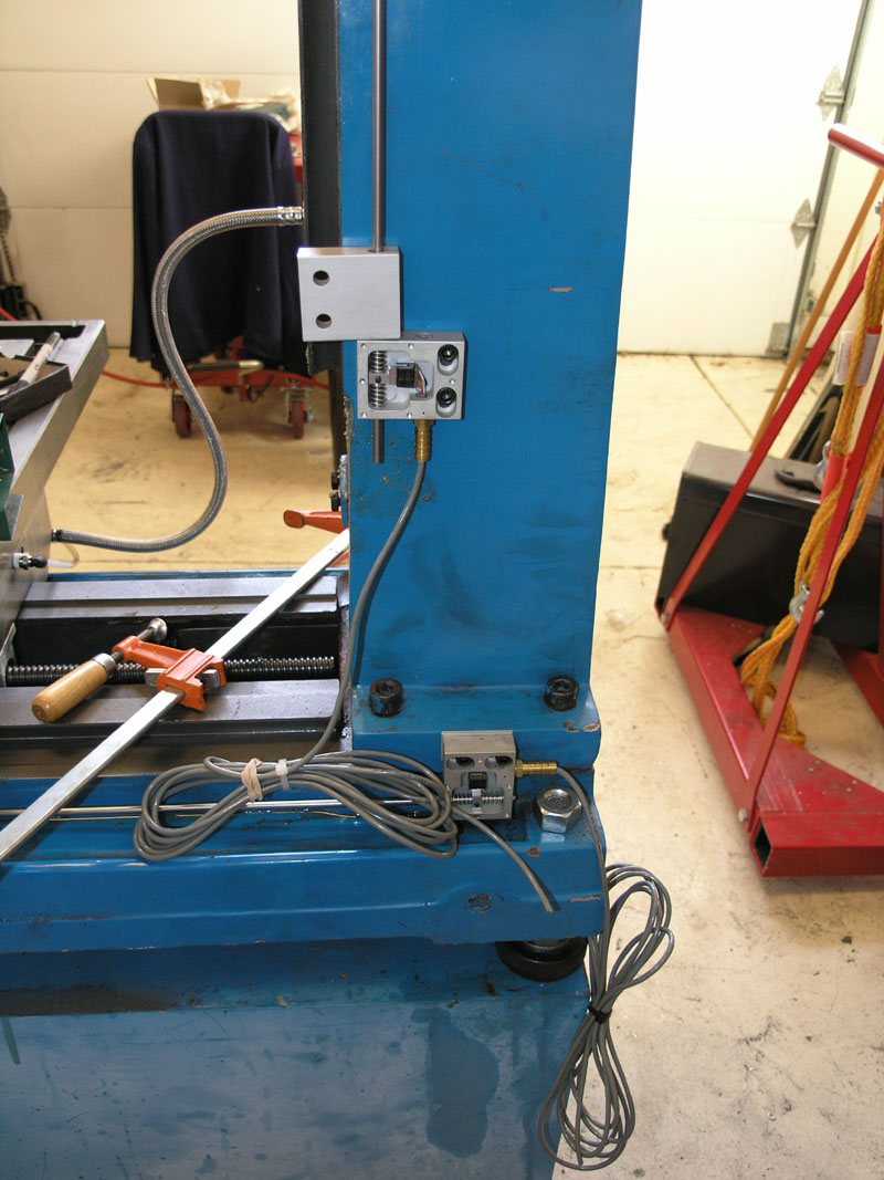
Here is a shot of the Y and Z-axis limits as they're being installed. These 2 use long rods with collars. An aluminum block such as you see on the Z-axis is bolted to the moving axis and when it contacts a collar on the shaft it actuates the switch...
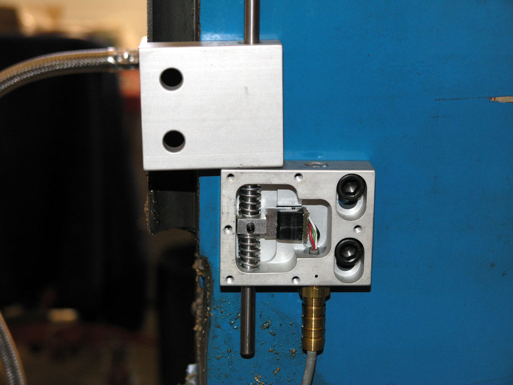
Here's a closeup of the insides of one of these nifty switches...
10/22/08
Electronics Enclosure Planning Sketch and Opening Key
This evening after I got done with work I made a key to open my surplus Rittal NEMA enclosures with. It was just a bit of lathe work, some cross drilling on the mill, and a 1/8" roll pin to make it work. I doubt if it took more than 10-15 minutes:
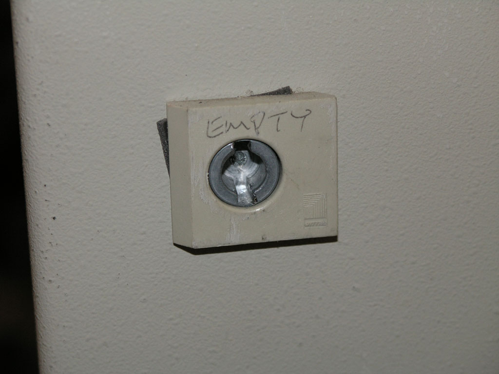
The lock...
The key I made...
First look inside the box. This should work out pretty well, I think!
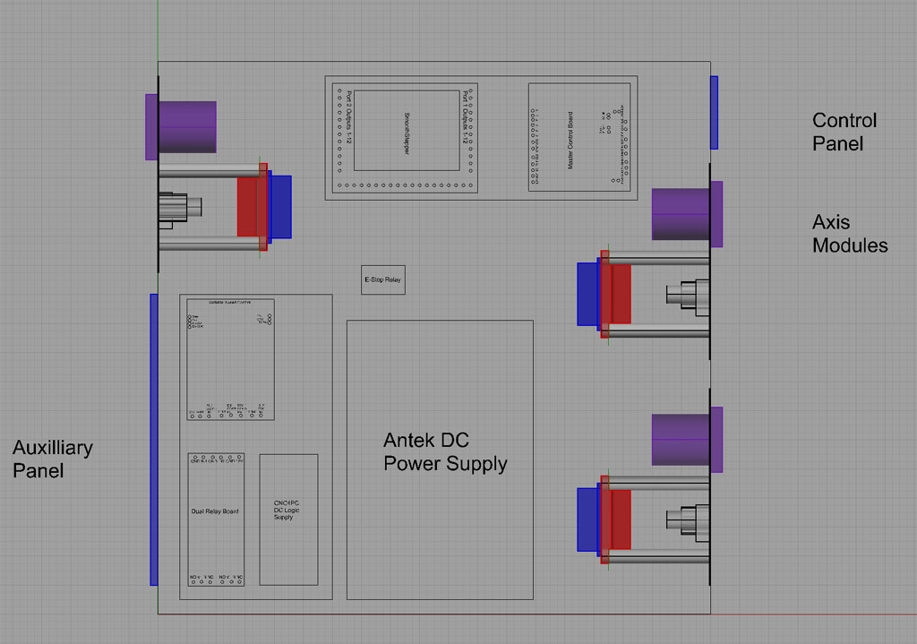
Having gotten the silly think open, my thoughts turned to how to stuff my planned electronics into it. I came up with this quick and dirty planning sketch using Rhino3D:
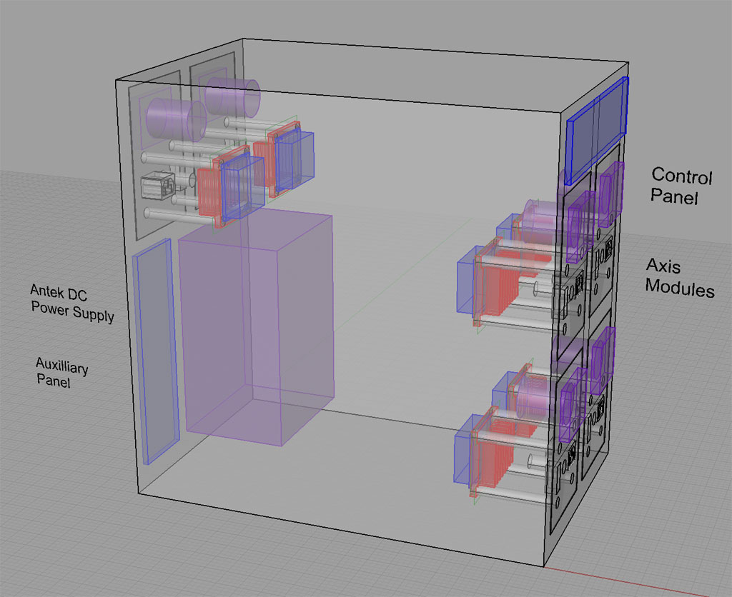
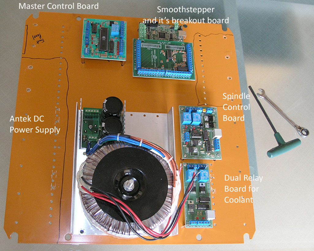
You can see I am planning for up to 6 of what I call "Axis Modules", as well as the Antek DC Power Supply. I'll need to squeeze a few other things in there as well, but it looks roomy enough to do so, eh?
In addition to this planning sketch I've mapped out which other electronics cards I need to order to provide all the functions of my CNC control enclosure. Full details on the electronics page.
10/12/08
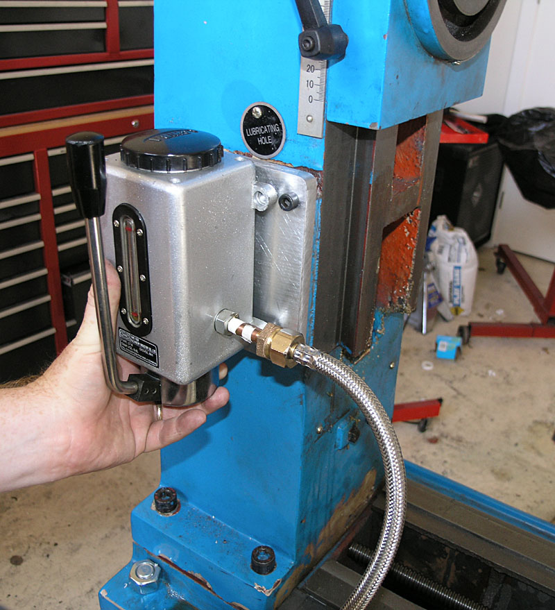
I'm Declaring the One Shot Oiler Done!
Got the pump mounted and the Z-axis plumbed. There are minor improvements I might make, but in general, it works well!
Here is a roundup of pictures:
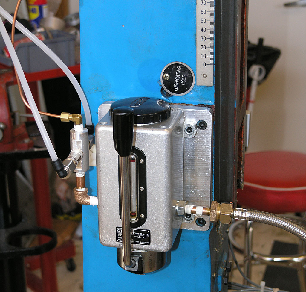
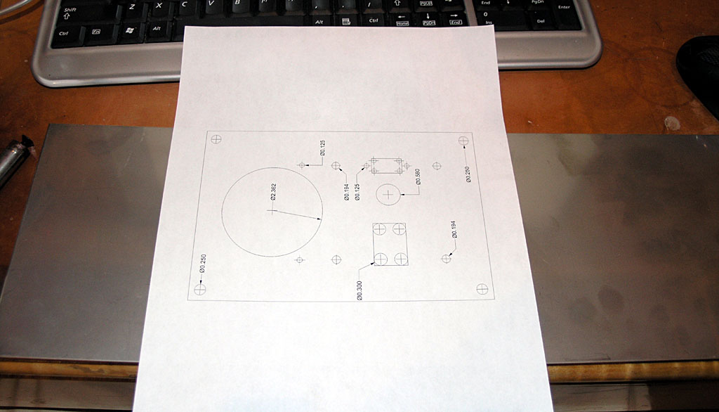
The pump mounted to the column...
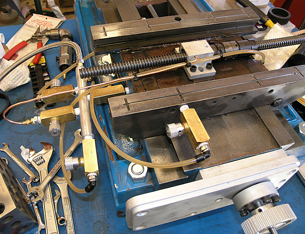
Shot of the saddle circuits...
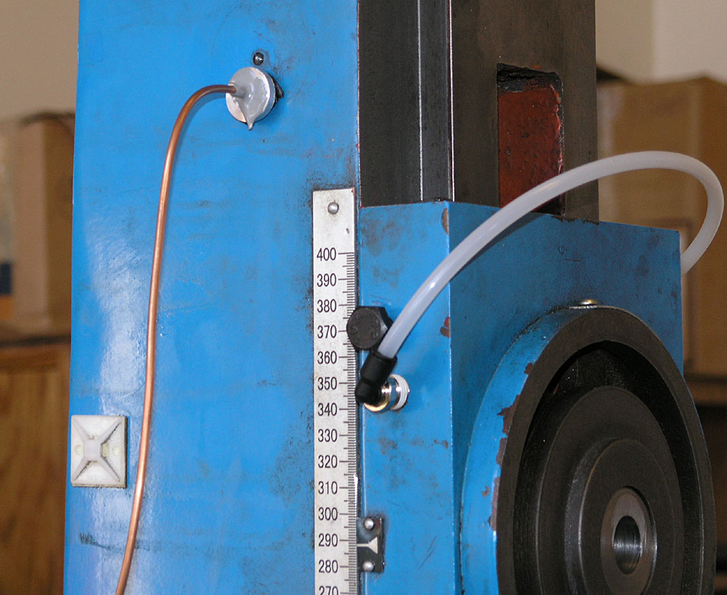
And the Z-axis circuits...
10/11/08
Ordered a 1000 Watt DC Power Supply to Run the Servos Today
I ordered a PS-10N70 power supply from Antek today to power the servos on my mill. Here is a photo:
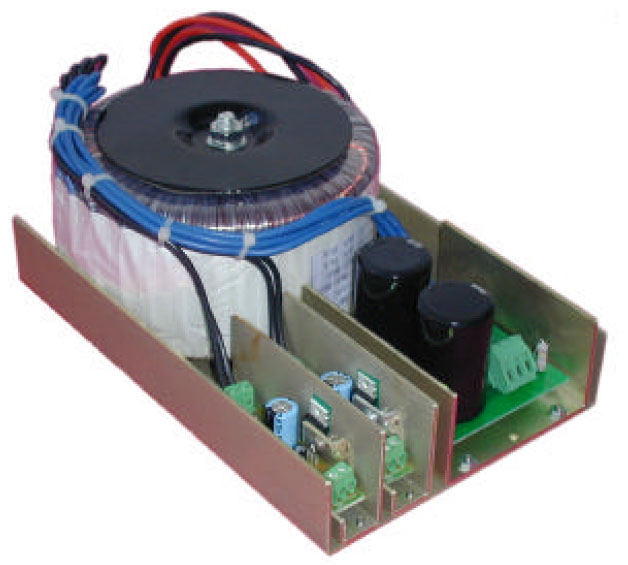
It was $150 + $10 shipping, which seems very reasonable. This is a 70V supply, which leaves a little margin for the 80V limit on the Geckodrives. Antek is run by a fellow named John Ango. I've ordered toroidal transformers from him before and he's a good guy to do business with. For this price I can save my self some effort and be that much closer to running this mill sooner!
10/05/08
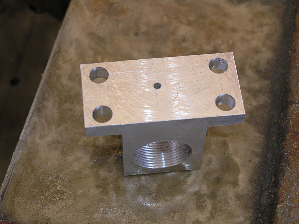
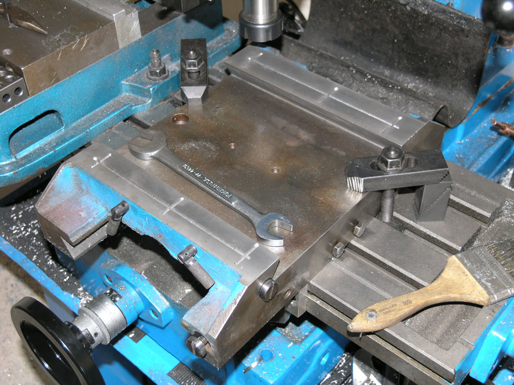
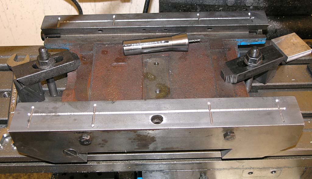
Block Off and Oil Pump Mounting Plate
Here's a quick shot, details here.
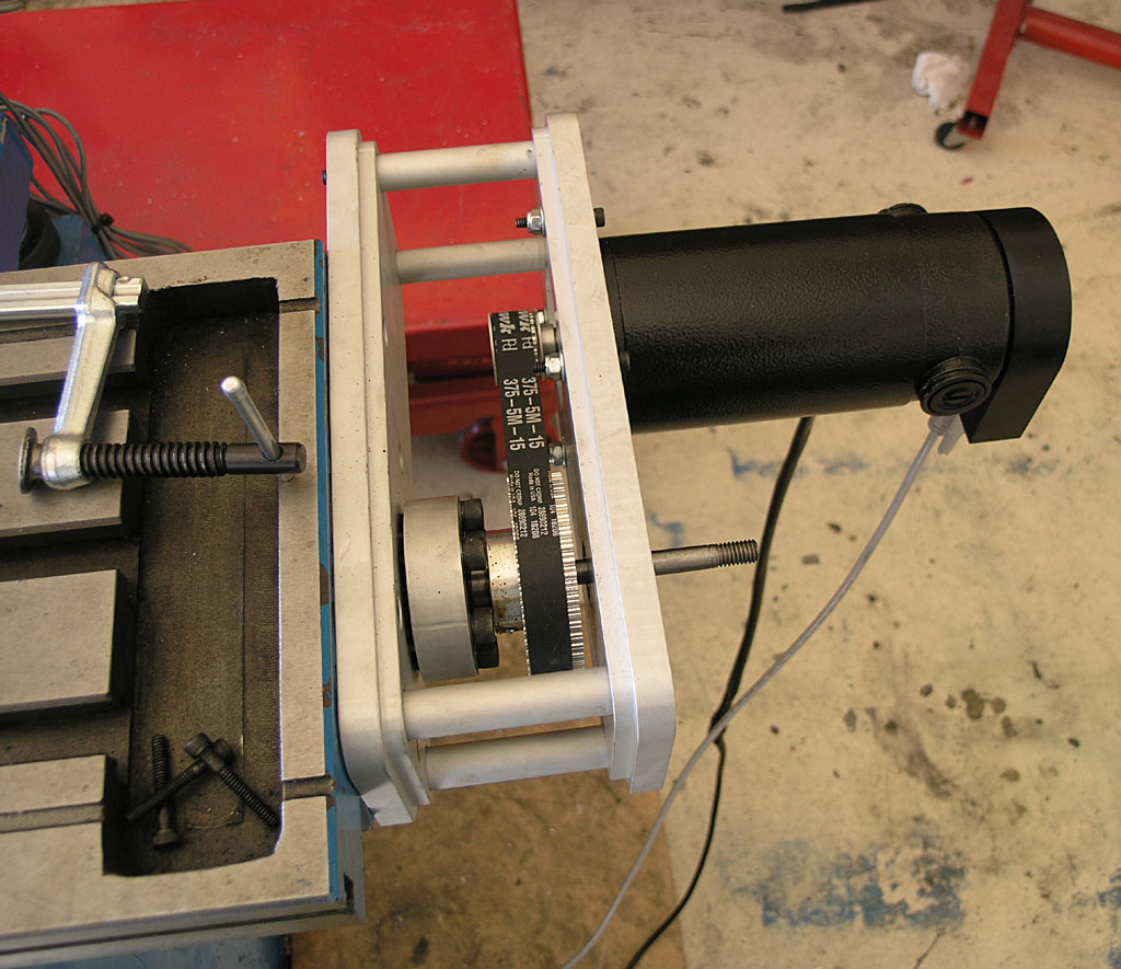
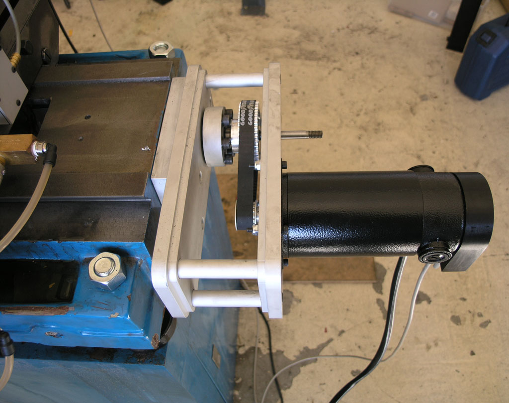
Ordered Timing Belts and Pulleys From SDP-SI and Musings About Encoders and Accuracy
The stock timing pulleys for the IH CNC kit are HTD series (semi-circular teeth), 5mm pitch, and 15mm wide. But, the pulleys that came with the kit have a tiny little 8mm bore designed for the servos IH sells. As I am using HomeShopCNC servos that have a 1/2" bore, they just won't work. There isn't enough meat on them to bore out that much. So, I had to figure out a new plan. After some fooling around to measure the shaft center distance on the bracket (it doesn't adjust, so you had better get it right!), I came up with a distance of 3.769". I plugged this into a Rhino3D drawing as a sanity check along with pulley diameters and actually drew up the stock arrangement. I came up with the small pulley having 12 teeth and the bigger one having 48 teeth for a 4:1 reduction ratio.
Measuring shaft to shaft with my 850 oz in HomeShopCNC servos. I knew there was a reason I had those big giant calipers!
Okay, so what's the closest pulley for the motor that will fit my shaft and work with an off-the-shelf timing belt without having to change the shaft to shaft distance or modify the bracket? Turns out SDP-SI has a nifty little calculator for this purpose. It didn't take too much fooling around before I figured out that a 72 tooth belt (instead of the stock 70 tooth belts) and a 17 tooth motor pulley would do the job. I ordered these from SDP-SI at a total cost of about $40. Not cheap, but the belts were half that and making 2 timing pulleys would consume a lot of time that I could not spend elsewhere.
Note after the fact (10/30/08): The 72 tooth belts don't fit but a 75 tooth works great with this pulley combination.
My reduction ratio on the X and Y axis will now be 48/17 or about 2.824:1 instead of 4:1. The stock IH kit comes with 410 oz/in servos but I'm running 850 oz/in, so I doubt I'll run short of torque. I'm running the 500 resolution encoders, but they're on the motor instead of on the ballscrew like the IH kit. So, IH gears down 4000 cpr encoders (I deduce given their 50 millionths resolution figure, hmmm) by 4:1 getting a resolution of 4000/4 = 1000 counts per motor revolution and 4000 counts per ballscrew resolution. Here is a thing about this 50 millionths figure from IH: none of the likely encoders from US Digital come anywhere near 4000 counts per revolution. 1000 was the highest I could find. How can they get to the 50 millionths figure then? The answer is not so hard, we use quadrature inputs which give us 4x the resolution for the encoder. So, if IH uses an expensive 1000 count per revolution encoder in quadrature mode, they get 4000 counts per revolution.
Let's assume I run my 500 count encoders in quadrature mode. I'm running the equivalent of 2000 * 2.824 = 2824 counts per ballscrew revolution and 2000 counts per motor revolution. So I appear to have about 70% of the resolution of the IH kit. Instead of 50 millionths, I'll be at 0.7 of a tenth. That's still pretty good! And note that this is actual resolution an encoder can see and a servo drive can do something about.
Steppers, by comparison, are commanded to move a step and have to just assume the proper motion occured. For comparison, let's look at the Tormach, which uses stepper motors instead of servos. I'm not claiming one mill is more accurate than the other, I'm just taking a look at how the numbers work out.
Tormach claims resolution of a tenth. That is defined as, "The minimum discrete position move is 0.0001", this is the resolution of motion."
What can this mean if we investigate closely? Given their definition, it means that 0.0001" corresponds to one step on their stepper motor. A typical stepper has 200 steps in a rotation, so that implies the gear train from step to table motion is 1.000" / (200 * 0.0001") = 50:1. That's a very big reduction, in fact it sounds too big. The IH reduction is 4:1 via pulleys and another 5:1 via the ballscrew, or 20:1
Tormach says their rapids speed is 65 ipm. Let's plug these numbers backwards and see what we get:
65 inches / 0.0001" = 650,000 ten thousandths = 650,000 steps per minute
650,000 steps per minute / 200 steps per revolution = 3250 rpm
Maybe they can rapid the machine while running the stepper motors at 3250 rpm, but that seems really fast for a stepper motor. Most of them in this kind of size range have a torque peak much lower than that. Tormach's Design Analysis talks about torque falling off rapidly in just a few hundred rpm. My assumption would be that the 0.0001" resolution is not realizable in practice and is based on something such as microstepping (the Tordrive has 10x microstepping, for example which would mean divide everything by 10 if we're talking microsteps). If I am right about the microstepping, the real resolution is more like 0.001", which is fine, and completely in keeping with the mill's stated performance.
Why doesn't microstepping count? Because you can't maintain full torque on a microstep unless it corresponds to a full step. They're largely about smoother acceleration and motion more than they are about accuracy.
I like the Tormach mill, BTW, I was just curious to work through the figures and see what I could learn.
Update on Tormach
I confirmed a few things from some Tormach owners on CNCZone. The Tormach direct drives the ballscrews with no reduction, and the lead on the ballscrews is the same as IH: 5 turns to the inch. So, at full rapids, the Tormach is doing 325 rpm as suspected. And also as suspected, you have to assume 10x microstepping to get to the 50 millionths resolution. My understanding was that you shouldn't count on microsteps for increased resolution because the torque was very low. That turns out to have been wrong. There is a great series of posts by Mariss F. on CNCZone that lay it all out. The long and the short of it is that you can take advantage of up to 10x microstepping and still have about 70% of the torque and full positional accuracy. Therefore Tormachs 50 millionths resolution claim is quite defensible.
Now of course there are other issues that prevent the machine from being that accurate in general, but Tormach only claims about 0.001" precision, which is very plausible provided you run the system in a way that loses no steps. A servo system still have the potential to be more accurate because it can get back on track after the fact. Whether that's acceptible or not to your application is a whole other question I won't delve into here.
It was gratifying to see that my math all worked out properly with the real data on the Tormach that I didn't have access to!
Getting Closer: Mill Column Installed
With the help of my brother and an engine hoist, we got the column up onto the base. This thing weighs 275 lbs before you put epoxy granite in it!
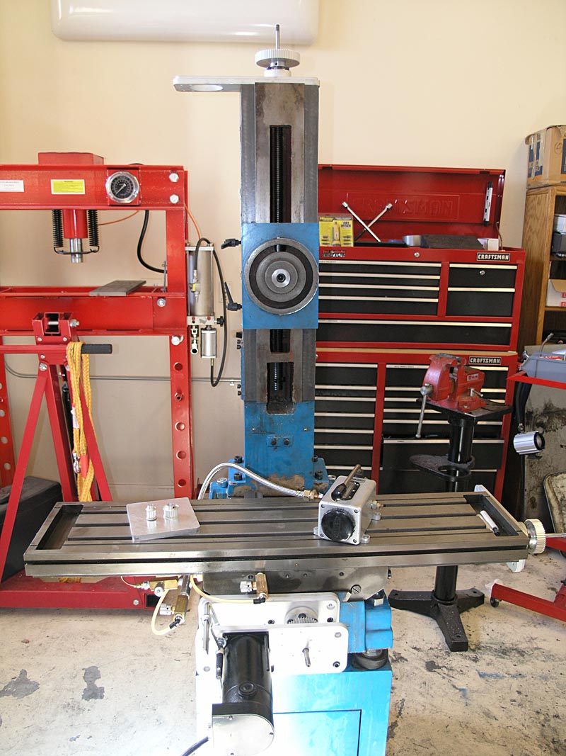
Starting to look like a mill now!
9/23/08
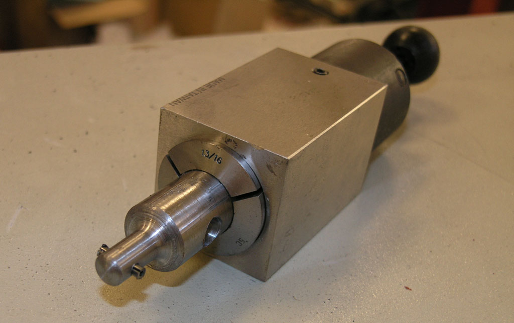
Cruel Teaser Sketch
Just the one "spy" photo of a little something I'm designing:
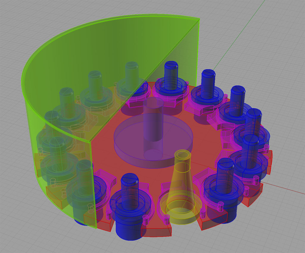
Curious how thee are two different kinds of tool holders, eh?
Too premature to say more!
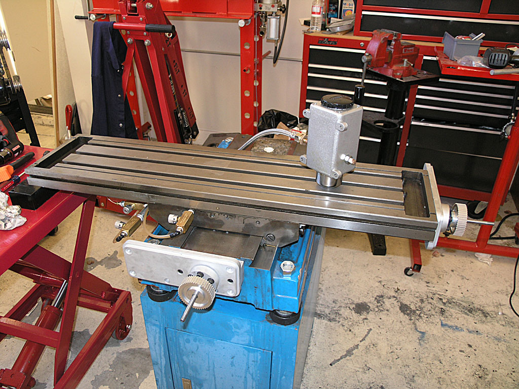
State of the Union: One Shot Works for X-Y and X and Y are "On the Bracket"l
There's been quite a lot of progress I've been slow to report on, so this is a catchup post in pictures in no particular order:

X-Axis is assembled and "on-bracket"...

One shot oiler for the X and Y axes is now up and running well. Between the way lapping and the one shot, I can tighten the gibs as tightly as they can go with a screwdriver and the axes still move like velvety smooth butter...
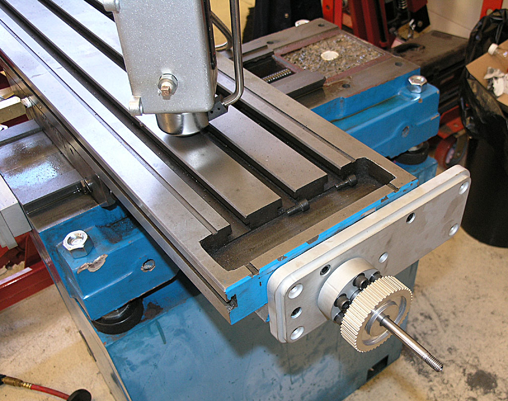
X-Axis is "On-Bracket"...
Here's Where We Stand: One Shot Works Great on X-Y. Ballscrews and Brackets are Mounted on X-Y
Next Step: Mount the Column. I made a change from IH's directions. If you mount the column and then try to install the ballscrew, it is hard to access the top of the column without a ladder unless your machine is on the floor. So I mounted everything temporarily and then disassembled it. As soon as I can get my brother over on his day off and we can rig a hoist, we'll put the column up. The holes for the mounting the ballscrew and servo are all drilled and tapped, so it should be fast. After that, I need to:
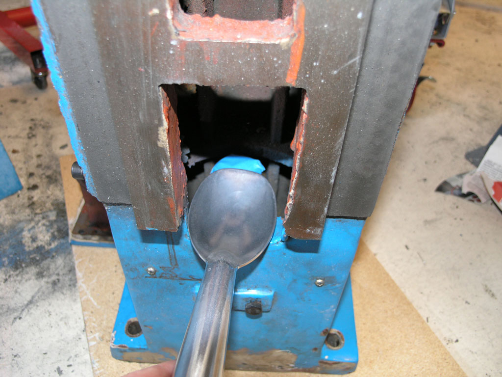
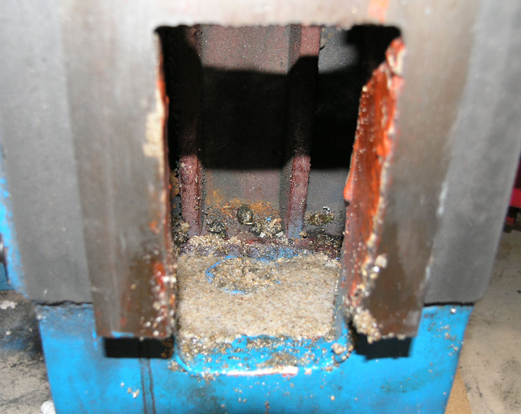
- Plumb the Z-axis oiling-note that there is a plugged outlet on the other side of the one shot pump for that
- Make a mounting plate for the One Shot Pump that goes in the opening for the hand crank on the Z-axis. It'll do double duty blocking off that opening and mounting the pump.
- Mount the servo motors. My NEMA34 frame motors fit the IH brackets just fine (yay!). I need to look at what's required to mount the timing pulleys to these servos, however. I also need to get a set of belts from IH.
- Mount the optical limit switches on all 3 axes.
- At this point I'll be mechanically complete on the conversion and it'll be time to start looking into the electronics.
Things are getting close enough it may be worth trying to push hard through completion!
9/02/08
Sears Labor Day Sale Yields CNC Cabinet For the Mill
I've ordered a Sears Gladiator Modular GearBox:
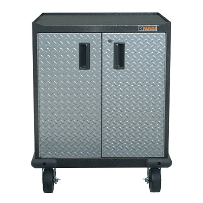
Inside is a cabinet with 1 shelf on slides. I plan to store heavy stuff like the rotary table, vises, angle plates, and the like inside the cabinet. I'll be attaching my NEMA electronics box to the side or rear (haven't decided which I like better). The PC and all the mill's electronics will go inside that NEMA box. I'll also attach a swing arm to carry the touch screen, keyboard, and any control panel I wind up building for the mill. I have a spot in the shop right adjacent to where the mill sits that is perfect for this little rolling cabinet. Should make for a very neat and professional installation. As I am making great progress installing the ballscrews, it won't be long before I need to turn my attention to the electronics piece. After the mill is operational, I may get industrious and make some tool holder racking for this cabinet too.
8/30/08
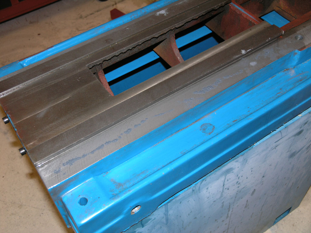
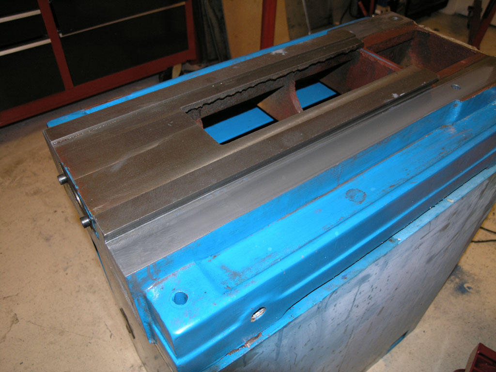
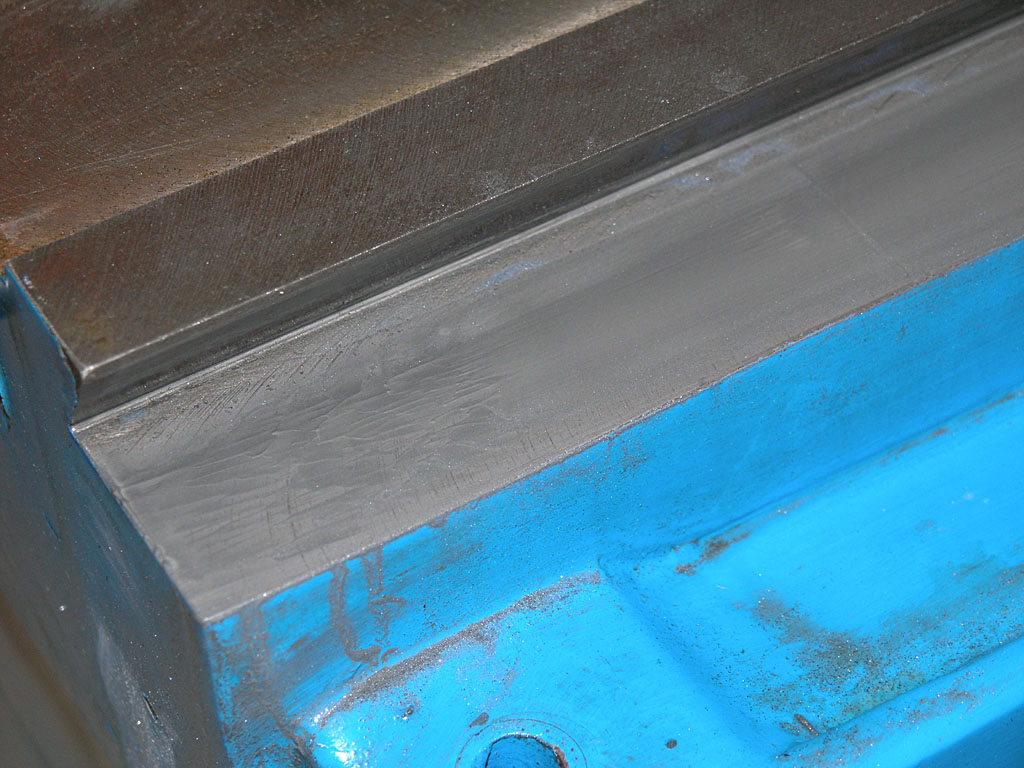
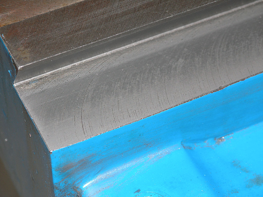
More Y-Axis Work: Oil Passage for Ballnut and Casting Relief for Extra Travel
To deliver oil to the cup atop the ballnut mount, I simply connected the oiling groove to the cup using a cold chisel and some gentle tapping. I only had to go about 1/8", so it wasn't hard to do.
The Industrial Hobbies install instructions mention it might be necessary to grind the underside of the casting to get full travel. They are right-there is a travel obstruction. Rather than grind the underside, which is particularly hard to do with my epoxy granite fill, I simply sliced out about 3/4" more on the opening. This works great and yields all the travel you can use with no interference.
8/24/08
Finished Up the New Y-Ballnut Mount
The ltitle center hole drops oil onto the ballscrew through a hole in the way above...
Just in Time to Start Installing the Kit: We're "On Bracket" for the Y-Axis!
Very spiffy looking, eh?
FWIW, I took down the measurements of all 3 ballscrews. They 0.2" per revolution, 0.75" diameter, and the lengths are:
X-Axis: 44"
Y-Axis: 28":
Z-Axis: 36"
8/17/08
Building a New Y-Ballnut Mount
Made rapid progress in a short time on this Y-Ballnut Mount:
The factory mount hangs off the edge and you lose 2 bolts. My new mount has all 4 bolts to hold down the ballnut...
Just finished threading it and it fits!
8/14/08
Finished Tapping and Cross Drilling the Oil Passages for the One Shot
Just back from vaca and had a couple of hours in the shop, so I did the X-axis today.
8/2/08
Tapping and Cross Drilling the Oil Passages for the One Shot
See the one shot page for more detail!
Tapping Z-axis...
Cross drilling...
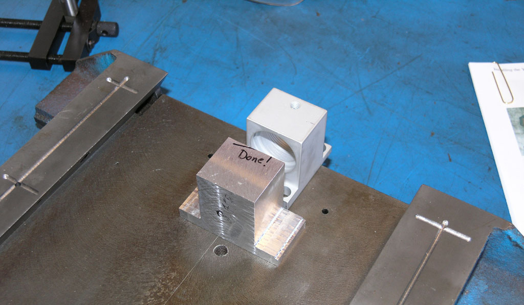
Z-Axis Ballnut Bracket Finished (Almost)
Full details on the web page. Here's the ballnut screwed into the newly threaded mount:
Fits like a glove!
7/20/08
Finished Epoxy Granite Filling Around the Column Bolt Pipe on My IH Mill
Just to make sure I was revved up to go to work on the mill this morning I watched a bunch of CNC videos on CNCZone. Then I went down, donned my nitrile gloves, and got back to making my epoxy granite mud pies:
Filling the cavity through the narrow slot was easiest with a cheap ice cream scoop I bought at the hardware store for $4...
I filled up to about 1/2" from the top of the pipe, and then I switched to a pure sand mixture to make sure the top was free of rock edges sticking up...
7/5/08
Preparing for the Column Pour
Since getting a new job in May I've been tied up for over a month before I could get back to my CNC work. I also had to finish up my little steam engine team build. I was able to carve out a little time over this Fourth of July three day weekend to make slight progress. I've basically epoxied a base plate into the bottom of the column along with a pipe that provides a bore for the big column bolt to go through:
The surface tension works nicely to let me apply a fair amount of epoxy. I just want enough to hold the pipe solidly so that when I flip the column over start adding the E/G mixture from above it won't break loose. I'll let this cure all week and then hopefully tackle the column fill next weekend. I've decided not to fill the column all the way up. This arrangement will fill the bottom 10" or so and should add considerable dampening without in any way being a clearance problem. I would think this will really help the mill to perform better to have this much added dampening mass in the critical junction between the base and the column. More would be better, but I'm anxious to get on with the rest of the CNC conversion and there is a lot of work to do!
5/25/08
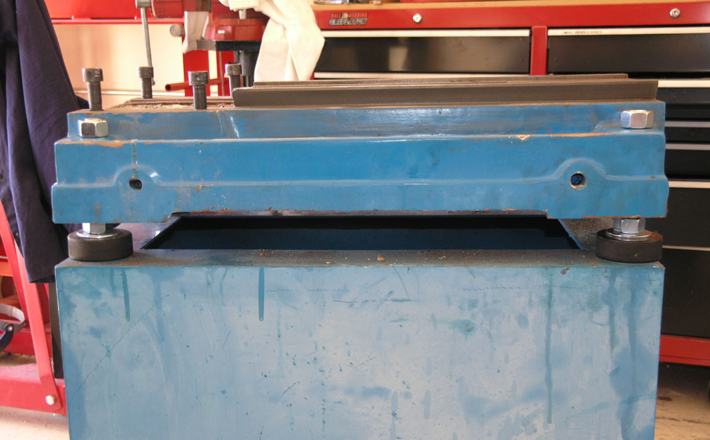
Hockey Puck Leveling Feet on the Mill
I finished this project a couple weeks ago but didn't get the pix posted. Full details on the page describing the process (scroll it's in there!), but they came out real neat:
Bought a Set of Servos and Gecko Drives from HomeShopCNC
After reading a note sent to me by Peter Tsukamoto, I got inspired to take a step of some kind on the mill to move this conversion forward. Peter started with a Unimat lathe 30 years ago and today he owns a full machine shop in Hawaii. Guys like that are always an inspiration to me, so I try to listen carefully when they have some advice for me. In Peter's words:
See if you can get your CNC mill going as a priority. It will open up new vistas in a way you cannot believe. It will accelerate any project you work on. Make them way more enjoyable too.
He makes a lot of sense there. Every time I perform a manual machining operation on my lathe or mill I think about what the CNC equivalent would be. In almost every case I could do the job much faster, more easily, and often better with CNC. There's a reason it took the industry by storm years ago!
A couple things have been holding up my progress. First, I've been spending a ton of time lately on a Steam Engine Team Build that has involved creating some tooling and a number of other things. The other problem that was distressing me was that I had misplaced the Industrial Hobbies CNC conversion kit somewhere in my house. I'd been looking for it off and on for days, and the number of places it could be was dwindling. After spending 45 minutes in the garage shifting things around and checking every last possible hiding place underneath all the junk, real panic set in. Paraphrasing Conan Doyle's Sherlock Holmes, when you've eliminated all the possibles, you have to start considering the impossibles. Eventually I discovered that my kids had pressed the two boxes into service to create a stand for their Karaoke machine. They were hidden underneath a black table cloth to make it even harder. I heaved a mighty sigh of relief after making that discovery!
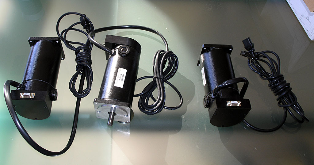
So, having located the components, I decided to take another step and ordered up a set of servos and drives from HomeShopCNC. I also looked at Keling as another source. HomeShopCNC was just slightly cheaper on Gecko drives, and I liked the nifty anodized housings for the encoders:
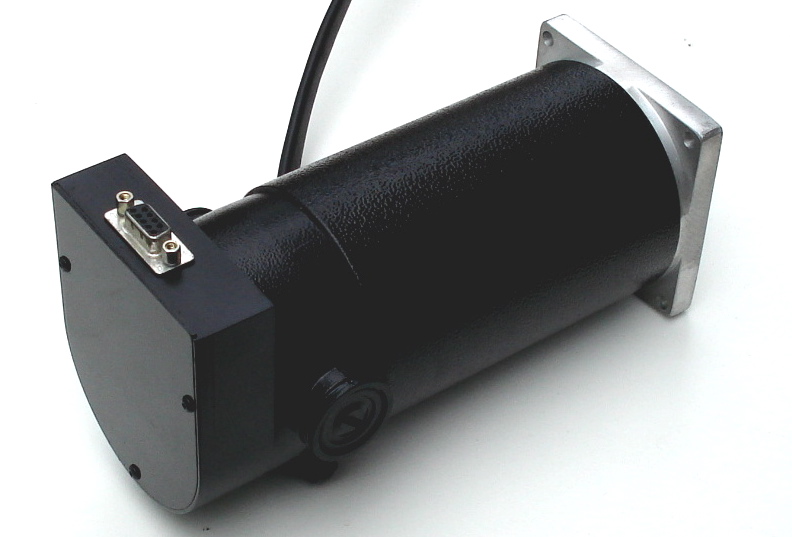
I like the nifty anodized housing for the encoder...
These are 850 oz in servos, and Keling had a bigger model at a whopping 1125 oz in. Why not just buy the bigger-is-better plan? Well, because there are trade offs. It's worth noting that the standard IH CNC kit comes with 410 oz in on the X/Y axes and 648 on the Z-that mill head is heavy! Their heavy duty kit looks to me like is substitutes the bigger Z servo on the X/Y axes. Either way, I should be fine with 850 oz in. Now here is the rub. The big Kelling 1125 oz in servo peaks out at 3200 rpm whereas the 850's I got are spec'd for 4200 rpm. I don't know if I'll ever get to use the extra rpm to increase my rapids or not, but bigger servos are often slower and the same is true of stepper motors. I think these 850's will be a decent compromise and they'll give me some room to experiment on my feeds and speeds. If the Z gives me any trouble I figure I can build a counterweighting system with some gas springs and radically reduce the force needed there too.
While I'm talking about alternatives, I should mention that I did some serious looking around for an alternative to the Gecko drives. Why? Customer Service. That's got to come as a surprise because Gecko has some of the best customer service reputation in the industry. The trouble is, I ran afoul of one of the counter examples of that. My GRex for my CNC lathe project has been a disaster. The good news: it was very easy to get it working, and I like the idea of not relying on the parallel port. In theory, it could save me a lot of trouble, especially since I had envisioned a fancy control panel for it. The reality? The device has never lived up to its original promises. It has had teething troubles since the beginning, and most of it has never gotten fixed. There are problems with 3D profiling on the mill that make it a questionable solution there, and the device doesn't support spindle indexing on the lathe, which is a requirement for threading. What good is a lathe that can't thread? Many promises were made over time about this being fixed, and we're talking a span of years. Unfortunately, it has never panned out. Gecko blames it on the firmware and says it isn't their fault. I think that's silly, and it certainly was not the story at the outset. I sent Mariss a note offering to trade my perfectly good GRex for a set of 3 of his cheapest servo drives (which combined were less than the GRex cost), and explained my problem with the GRex. I never even got a response back from Gecko. That's just not good customer service in my book, despite their stellar reputation.
So how did I wind up buying another set of Gecko drives anyway? Here's the rub-who else is there? Rutex is in an odd state. The parent is Australian, and the designer has gone missing there last I heard. Reports vary on whether the boards can be gotten here though the US distributor says yes. Last thing I want to deal with is another strange situation with one of these boards though the Rutex has a lot of advantages over the Geckos on paper, and there are certainly those who swear by them. I also looked at the UHU family of servo drives. These look to be excellent, but so far they are either awfully expensive if you buy one already built, or you deal with cobbling together a kit. Frankly, I was tempted to go the kit route anyway, just to avoid Gecko. I enjoy building electronics and I'm pretty good at it. The trouble is, Peter's words kept nagging at me. How much would it set back my conversion to have to build and debug 3 servo controller boards? So I got the Geckos. They were cheap when bought with the servos anyway.
Still, it wouldn't have taken much to get me to buy something from someone else. I guess that's the power of customer service. Given his reputation, I can't understand why Mariss wouldn't do something for me. Oh well, I sure hope these new drivers are flawless or I will build the UHU boards.
4/6/08
Bought a Toroidal Transformer for the Servo Power Supply Today
I plan to build a DC power supply similar to the one I did for my lathe to run the servos. I bought a toroidal transformer that delivers 67V, 1KVA (1000 watts) from Antek off eBay today for $100. It's a good price and I've dealt with Antek in the past. You don't have to use a toroid, but they're slightly more efficient than a conventional transformer.
When I get done working on the steam engine parts for my team build, the mill will be free again and I plan to start building the electronics, so I wanted to be sure to have the parts on hand if they became available cheaply.
3/4/08
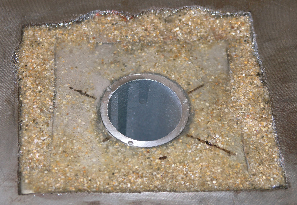
Epoxy Granite Mud Pie Test Was Successful
Here's what we got the next morning:
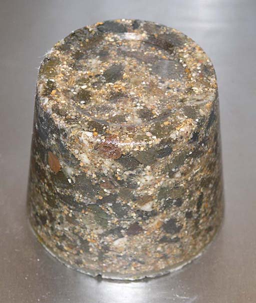
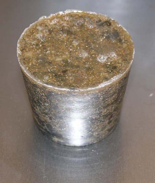
Test was successful!
The test was successful. The aggregate is embeded in the epoxy. The slug took a very accurate impression from the cup-you can even see scratches made in the plastic by the gravel's sharp edges are faitfully reproduced. I suspect creating a precision surface in this material is easy if you have a precision mold. The material released easily from the plastic cup-just a couple sharp raps on workbench and it dropped right out. The ugly parts are at the air-epoxy interface from the top of cup. There are various approaches to eliminating the air bubbles, but it doesn't seem like there were many bubbles trapped in the material from the mixing process-they're all at the top. A quick pass with a heat gun is rumored to be the quick trick to get rid of those.
At this point, I can't see much point in monkeying with success. It may be that a 10% epoxy formula would be better, but this will work just fine for this project. I plan to keep Epoxy Granite in mind for other projects. I understand it sets up with an accuracy of 0.001" on top if you get rid of bubbles, so you could make a surface plate from it.
3/3/08
Making Epoxy Granite Mud Pies
I put together a trial batch of E/G after experimenting with various sand and gravel mixture ratios. It's a mud pie:
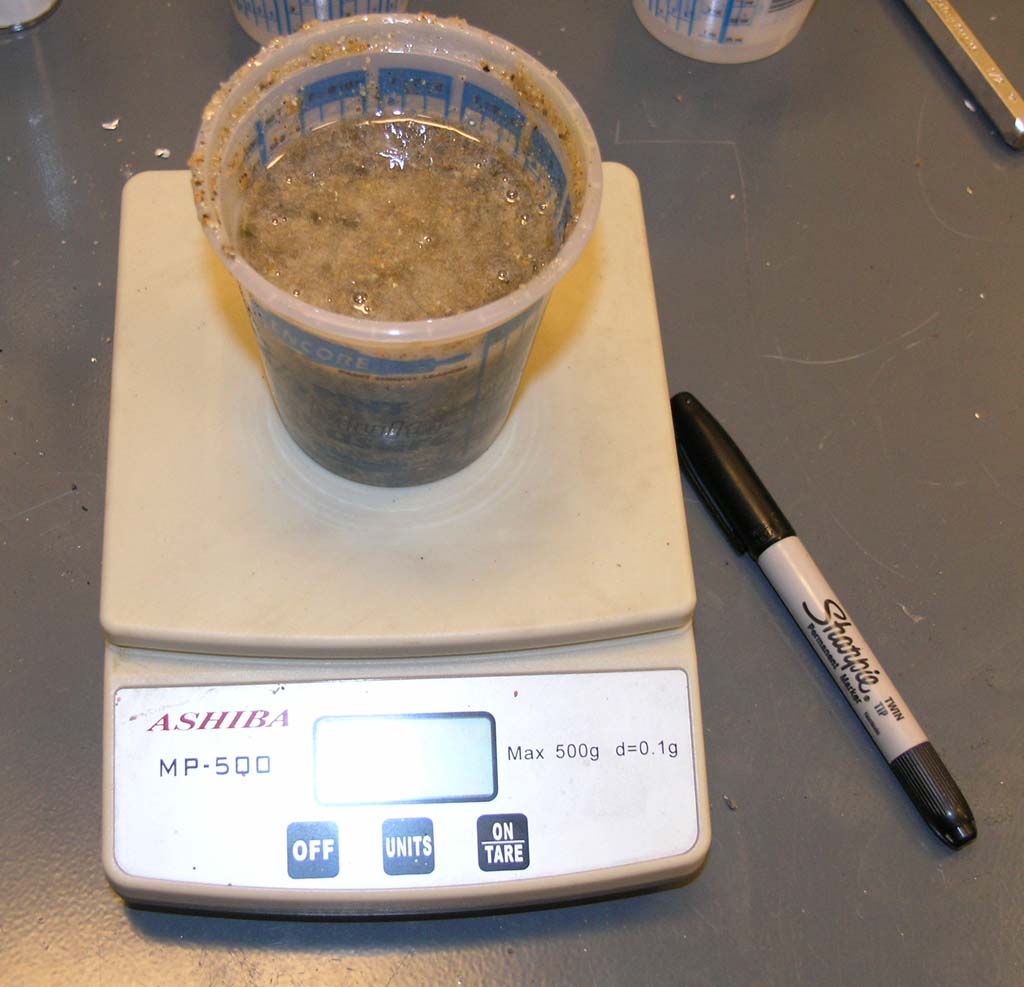
The mixture I arrived at wound up using these proportions by weight with epoxy resin:
- 62% gravel
- 23% sand
- 14% epoxy resin
That worked out pretty darned well if I do say so myself as I was shooting for a little under 15% epoxy resin by weight. In terms of volumes, this was 1/8+1/4+1/3 cup of gravel, 1/4 cup of sand, and 1 1/2 pumps each of resin and hardener. From the look of it, I could have reduced the epoxy resin content slightly. At one point it seemed to dry, but as I kept stirring and getting all the aggregate coated it turned liquid again and life was good. We'll see how it turns out tomorrow after it has cured overnight. If the test is successful, this is going to be a remarkably easy thing to do!
3/1/08
Started Working on the Epoxy Granite Fill for the Base
I'm going to fill the base with Epoxy Granite to increase dyname stiffness. Check the Epoxy Fill Page for full details, but here is the containment system:
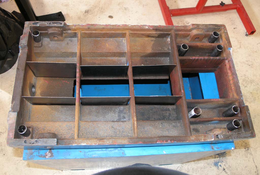
Sheet metal and steel tubes will keep the epoxy confined to where it belongs without gumming everything else up!
Oil Grooving Completed
I got the X and Y axis ways grooved (more details on the one shot oiling system page):
Y-axis...
X-axis...
2/23/08
Started Installing the One Shot Oiling System: Z-Axis Modifications
I got started with my one shot oiling sytsem by cutting oil distribution grooves in the Z-slide. It works well!
I tried it out and got a wonderful even distribution across the ways...
And I finished the Z-axis rigidity mods. Next I'll need to do the Z-axis ballscrew mounting mods.
2/22/08
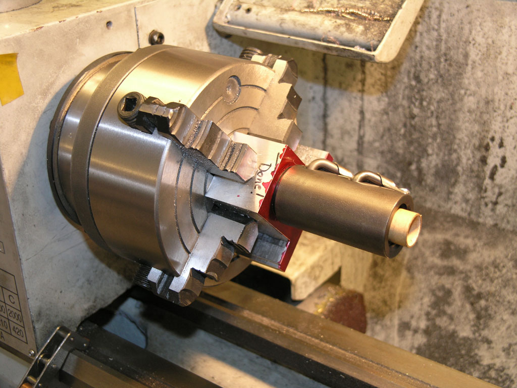
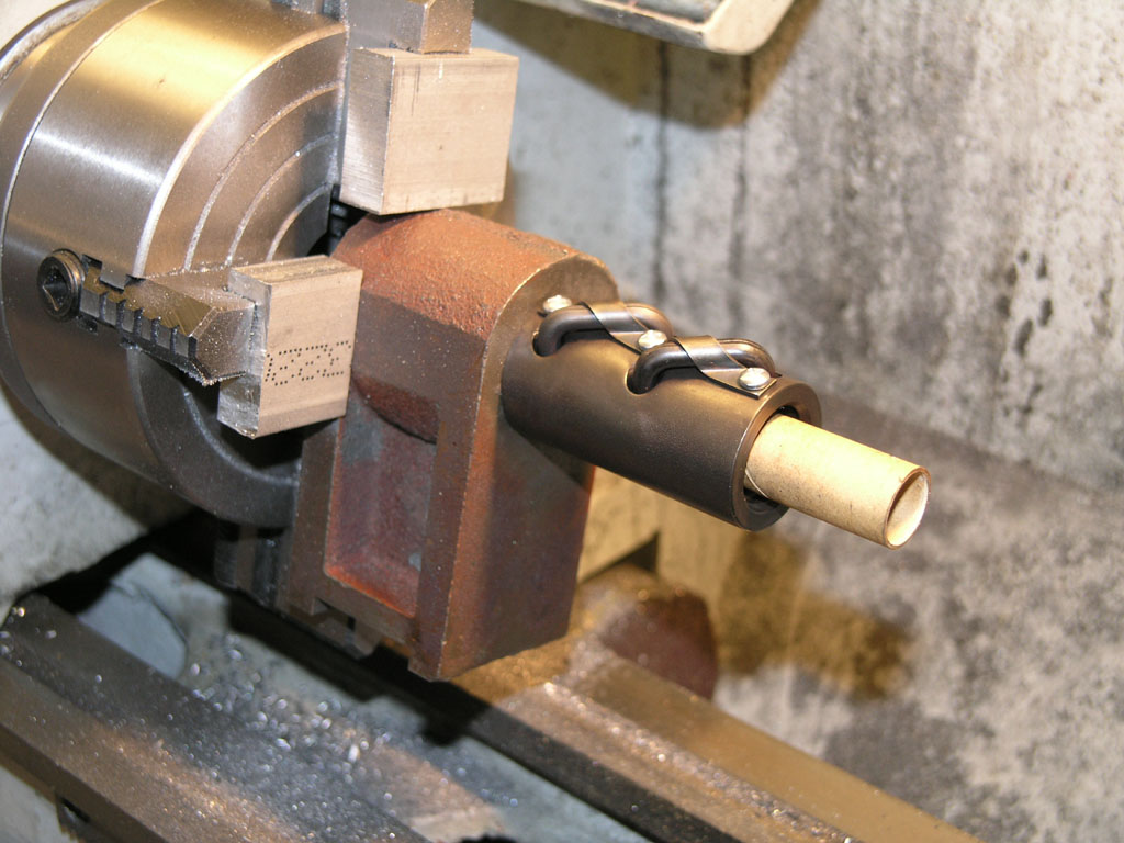
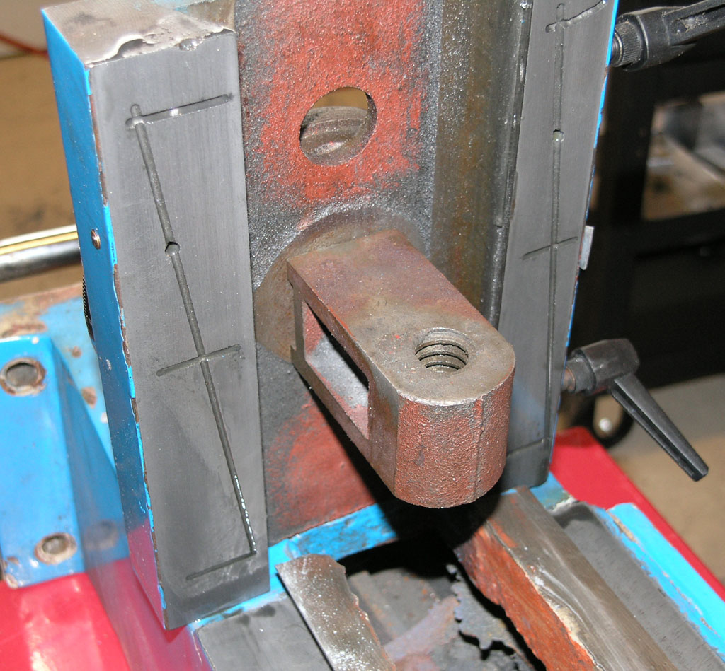
Started to Modify the Z-Axis
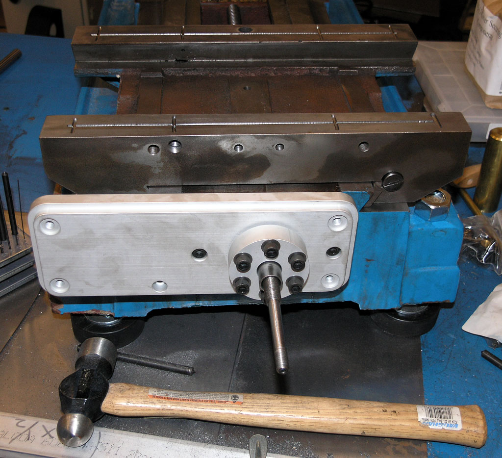
There is a significant source of slop in the Z-axis that requires a modification. This is the bracket that attaches the Z-axis slide to the leadscrew. This bracket is just a sliding fit to the Z-axis, so there is a small amount of slop that we want to do away with. The modification is described on the Industrial Hobbies web site, and can be done to almost any RF-45 mill. It involves creating a new bushing that has a shoulder on it so that you can bolt it down and squeeze the Z-axis saddle between the shoulder and the leadscrew bracket.
You can check out my progress with this Z-axis mod as well as adapting the bracket for the ballscrew on my Z-axis mod page.
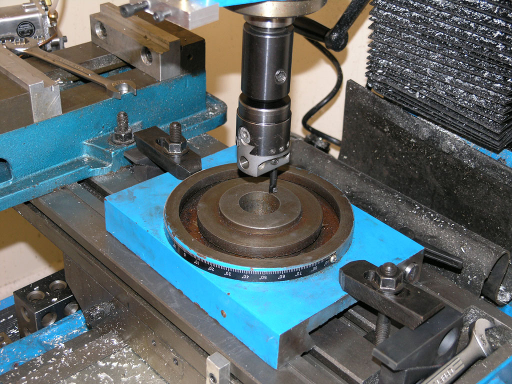
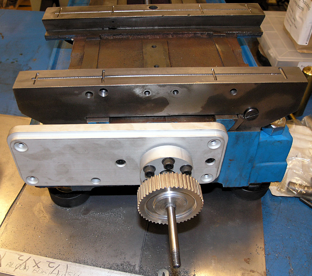
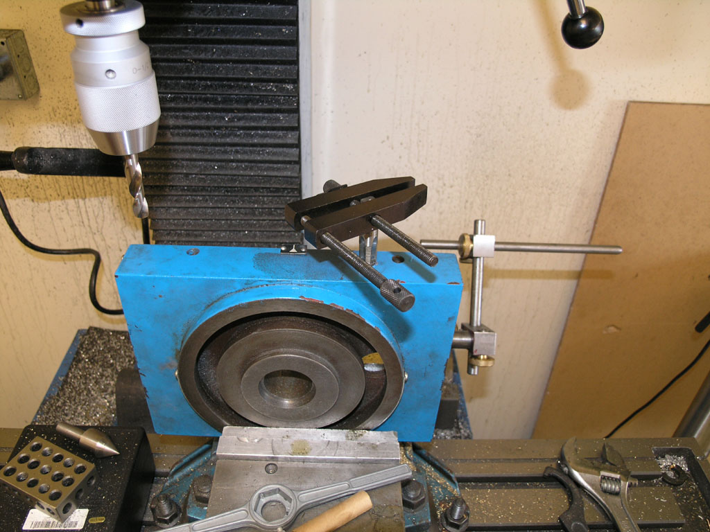
Here is the boring head gearing up to cut that shoulder...
Lapping Finished!
I completed the lapping of all ways yesterday. The hardest part is wrestling the heavy components around. I did the Y-Axis by myself, but talked my brother into being on hand for the table and column. As we finished each axis, I thoroughly cleaned the axis with kerosene, applied generous way lube, adjusted the gibs until as tight as I could get smooth motion by hand and then checked out the feel of the axis. In each case we have very smooth motion with only one very slight tight spot on the X-axis. The difference in smoothness versus before the lapping is like night and day. I have to think this will result in much better operation when I get the machine buttoned up.
Here are the two remaining axes shortly after we completed the work:
2/18/08
Y-Axis is Lapped!
I completed the lapping on the Y-axis today. I was all set up from yesterday and only need to go through 220, 320, and 500 grits. All told it took about 40 minutes. Here are some pictures of the event:
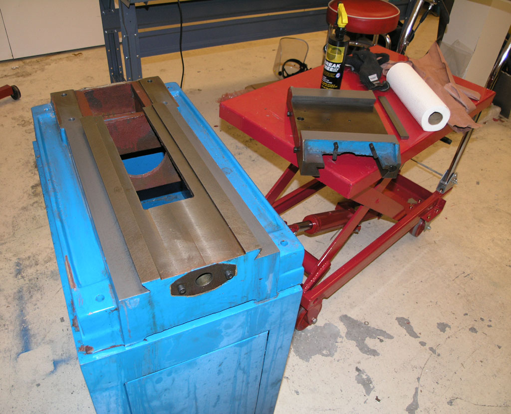
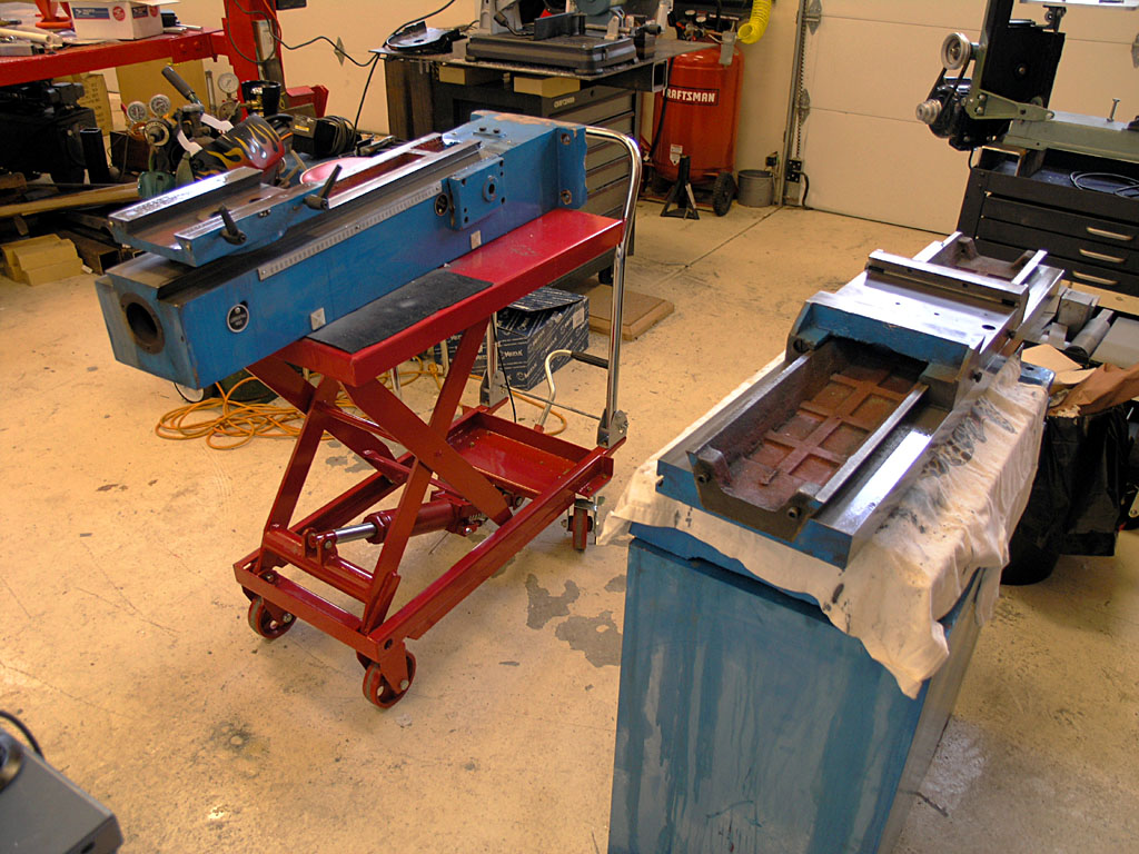
The mill base is setup on the IH mill stand per their instructions. The lift table (some call it a die table) on the right is essential when moving heavy stuff around the shop. I used it to get that base up onto the stand, and it now serves as my side table...
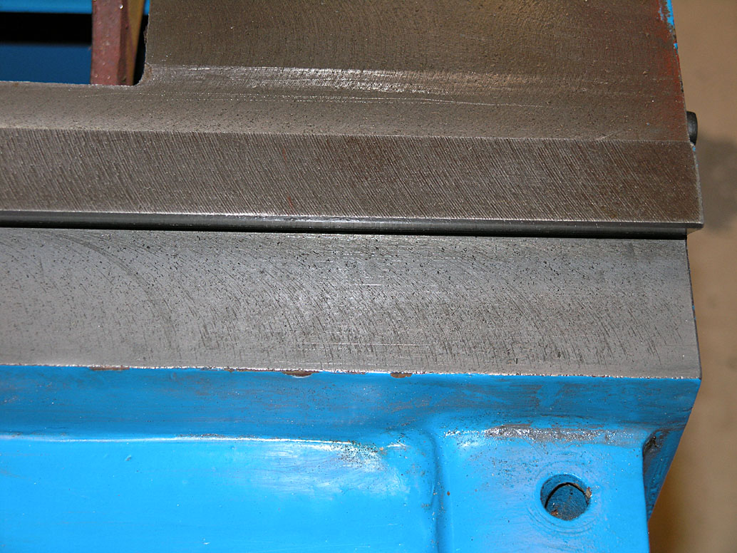
Here are the ways after the first two grits: 80 and 120. Cutter marks are still very visible from the manufacturing process. We're lapping in order to tone them down so the ways have less friction...
We apply kerosene to the ways and then a pinch or two of grit. Then the saddle is placed on the ways and stroked back and forth the requisite number of times allowing for at least 50% overhang at each end of travel...
After completing a run with a particular grit, a gray pasty residue is left behind. It consists of grit and ground off way material (cast iron). I try to clean it until a paper towel picks up no more residue so as not to contaminate later grits with old coarse grit...
A little closer look at the paste. Note we're not getting right up against the dovetail too well. That's beacuse this is still the 220 and I've only started to put the gib in at this point. That was again per IH instructions...
And here is where we got to after the final grit. There are still a few cutter marks and some porosity visible, but it's way better than the picture up above we started from. That's what we're looking for!
And, as IH says, we aren't going to try to eliminate every last tool mark. To do so is to invite going too far and possibly compromising the trueness of the way. This is an adequate compromise. What I think will really help is tying these new smoother ways with my one shot oiler, which will ensure much more consistent lubing than I've had in the past.
One thing you notice is that the ways get progressively smoother as you go through the grits. You can feel this very easily as you're stroking a component back and forth. It is particularly obvious when you insert the gib, run for a bit at 220 grit with the gib loose, and then are finally able to tighten the gib and still get smooth motion. I doubt very much I could've moved the saddle with the gib in and tightened and nothing but kerosene as a lubricant before I started this process!
2/17/08
The process of conversion began today. My second IH mill has been sitting on the shelf for a little over one year, and I decided to finally get going on the conversion work. Fortunately, the mill was disassembled before being put away for storage. Equally fortunately, I applied a treatment of Break-Free rust inhibitor to all the bare metal surfaces, so there was no rust to speak of visible anywhere.
Why Lap and is it Dangerous for Machine Accuracy?
The first step in the process is lapping the ways. I'm starting here because my next stops will be installing a one shot oiling system and filling some of the castings with epoxy granite to help dampen and stiffen them. I don't want the one shot oil passages to get grit in them, so I need to finish lapping before I begin that task.
Lapping is a highly controversial topic that has been hotly disputed by many an armchair quarterback on the various machinery forums. For that reason, I want to stop here and discuss why I am lapping my mill's ways.
First and foremost, I am doing it because after considered discussion with Aaron Moss (the original owner of Industrial Hobbies and likely the world's foremost expert on these mills) I am following his advice. Aaron has lapped many a Chinese mill and swears it is always an improvement. The reasons are twofold. There is a reduction in friction of the ways which helps to reduce stick slip and makes the motions smoother. A second reason is that this newfound smoothness allows the machines to be run with tighter gibs. The upshot is a more accurate and tighter machine. Whatever we may sacrifice in the ultimate trueness of the ways is more than made up for by smoother motion and tighter gibs. I trust Aaron totally on this, and he has the experience to back it up.
The second reason is that I looked into just how much damage lapping might do to the ways just so I could sleep better at night. The difficulty that this discussion always raises is that lapping will by its nature reduce the accuracy of the ways, making them rounded rather than true.
I did some Internet research in an effort to quantify how much material the lapping process may be removing, and thereby how much inaccuracy might be induced by the process. One source indicates that a typical lapping procedure will remove 0.0002" - 0.0005" of material. Another article found that the mean rate of material removal using diamond cutting compound (much more aggressive than the simple aluminum oxide that Aaron Moss recommends for lapping ways) was 0.0004 mm/minute = 0.000029"/minute. Note that these two references involved use of lapping machines and near optimal conditions for maximum material removal.
Let's briefly consider the schedule lapping suggested by Industrial Hobbies:
Grit
Strokes
80
20 - 30
120
40 - 50
220
40 - 50
320
40 - 50
500
40 - 50
In comparing this schedule to the published material removal rates, let's assume lapping can proceed at the equivalent of 1 stroke per 2 seconds. In essence, we are then talking about 230 strokes being the equivalent of less than 10 minutes of lapping on a machine. Since the grits are made progressively finer, it is probably more equivalent to half that on average, but even if we went at it for a full 1 hour the material removed would be 0.0017" in the absolute worst case. At 10 minutes, we're looking at about 3 tenths. My suspicion is that it is more likely way less than half or even a quarter as much since this approach to lapping is not going to produce optimal material removal rates. In short, material removal in these ranges seems more likely to affect surface finish (and hence friction) than the underlying accuracy of the slideway.
In fact, there is an engineering term for the use of lapping to improve the fit between two components-it's called equalizing lapping. To further cement the case that this is what we're doing when lapping the ways, one uses a hard lap to avoid embedding of the grits in this type of work. Lapping to change the shape of something is called form lapping. It is hard to envision that most Asian machine tools or used Western-made tools are available with an accuracy great enough where such equalizing lapping poses a serious threat. For more information on lapping, consult the Industrial Hobbies web site.
And by all means, follow your own conscience on the matter of whether to lap your ways or leave them alone on an RF-45 mill. Importantly, the latest model IH mills have the ways more carefully ground, so there is no longer a need for lapping on these mills.
The Process
I followed the lapping directions on the Industrial Hobbies web site to the letter. Tonight I began with the Y-axis. I was able to go through the first two grits, 80 and 120, in about 1 hour. This included initial setup, dragging the mill parts out of storage, setting them up on a table, and the actual lapping itself.
The work itself is extremely simple. I irrigate the ways with kerosene to act as a lubricant. Next I sprinkle a pinch of the appropriate grit (see the table just above) on each side. Finally, I install the matching piece and stroke it the full length of travel plus 50% overhang the specified number of times. I try to do this smoothly and steadily while keeping the ways in contact on the side without the gib. Initially, we're told to go without the gib and to lap it separately. When I get to 220 grit, it will be time to install the gibs and go from there.
At the conclusion of these two grits, the ways were noticeably smoother. They'd had some ridges not unlike a file when I began and these were all but gone after the first two grits. So far so good!
Knocking off for the evening as it's about 9:30.

**
Be sure to check out G-Wizard, our Machinist's Software!**
Be the first to know about updates at CNC Cookbook
Join our newsletter to get updates on what's next at CNC Cookbook.