Elmer Verburg's Reversible Open Column Steam Engine Team Build
I'm participating in a Team Build of a small steam engine with a group on the HMEM board. I'll document our progress here.
In a Team Build, a group of machinists work together to create multiple copies of a project. Each machinist is assigned one or more parts, which are then assembled by the Team Captain and shipped to team members. This approach is a fun alternative to working solo and offers a great learning opportunity. As home shop machinists, we often work on one-off projects, leading to the habit of machining parts "close enough" and adjusting other parts to fit. While this reduces scrap, it's not the most precise method.
For a team build, you have to build your parts to close enough tolerances that somebody else's parts you've never seen will fit. The other learning opportunity has to do with making more than one. In this case, there are 12 copies of each part to be made. And, if you're like me and some do get scrapped, there are actually more. Hence it pays to think about how to save yourself some time on repetive work. I actually wound up creating a fair amount of tooling for this project. Nothing in the way of special-purpose features, but there were 3 new pieces of tooling and one old that were indispensible:
- 5C Collet Chuck: This cheap little chuck had lain on the shelf for almost two years after I got it for a bargain. Through some heroic efforts I took a chuck that would've been good to 3 - 5 thousandths and made it repeatably accurate to 2 or 3 tenths. It has been a real productivity enhancer for this job, and I don't know how I ever did without a collet chuck in the past. With the collet chuck goes an inexpensive imported square collet block so I can carry the work over to the mill as needed.
- Button V-Block: This handy fixture was inspired by a Dubosky article from my Metalworking book. It is a round V-block instead of the normal square ones and is ideal for certain operations such as small connecting rods. Easily made and indispensible.
- Compound DRO: I have no DRO on my lathe because it is my intent to convert it to CNC operation. Yet, a DRO makes things so much easier. The one I use most in my shop has been a simple quill DRO I made for my mill. The lathe equivalent of a quill DRO is to put a scale on your compound slide. It's amazing how much mileage I've gotten out of this on this project in exchange for barely an hour's work and a cheap import digital caliper I never liked anyway.
- Vise Stop: I made this a while back, but it really has been useful on this project.
Lots of other tooling was involved, of course, but those four items really made this project possible and were all things I made for myself (or at least the backplate on the collet chuck I made!). If I add up the time spent on the tooling, it would come close to exceeding the time spent making the parts, and certainly would exceed if we count the vise stop which I made some time ago. Was it worth it to spend as much or more time on tooling as parts? In my mind, it was, simply because this tooling will make me more productive on future projects. Certainly the collet chuck vise stop, and compound DRO will have extremely broad applicability. Still I do somewhat hope every new project doesn't require me to build so much tooling! It's one reason why I probably buy more off-the-shelf tooling than many. For example, even though I could easily make a set of machinist's jacks, they're so cheap at Enco, and I've got so many projects to get done. Most of the tooling I list here is harder to buy off the shelf or a lot more expensive than the jacks!
Plans
Plans are available in pdf format here.
Flywheel: Part #1
I have two parts assigned, the flywheel and the connecting rod. I've decided I need to get my collet chuck going to do the con rod, so I'll start with the flywheel:
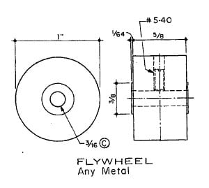
I'll be making 12 of these beauties, all in brass.
I've recast the drawing to use decimal rather than fractional notation:


Flywheel Production Line
Here is a pictorial description of how I finally settled on making my 12 flywheels.
Rough Cut the Stock

Face and Turn True in a Collet
Start out slicing the rough stock. I'm using my DeWalt Multicutter carbide saw to do this. Each slug is about 1" long. I deburr one end of each slug with a Roloc wheel that has some 80 grit and an air die grinder. You just want to knock the rough edge off so it doesn't interfere with the collet...

Inset the deburred edge into the collet and tighten in the chuck...

First operation is facing. Just take enough so the whole diameter is faced. This is a good time to fine tune the tool height to minimize the nub in the center...

Now turn the piece. Just take off enough so it is round and machined all over. Don't run into the collet!
Turn to 1.000" Diameter

Take your digital calipers and get a rough sense of where you are. I'm shooting for a 1" diameter and my measurements were typically 1.050-1.090 or so. Based on that measurement, I ran the dials until I thought I was within a couple of thou...

Check the last couple thou with the mic, do the finish pass, and mic again to be sure. A habit that saves me time is when I retract the cross slide, I retract exactly one revolution from wherever I was. That way it's easy to remember how to get back to cutting...

Faced and turned to 1" diameter...
Bore and Ream

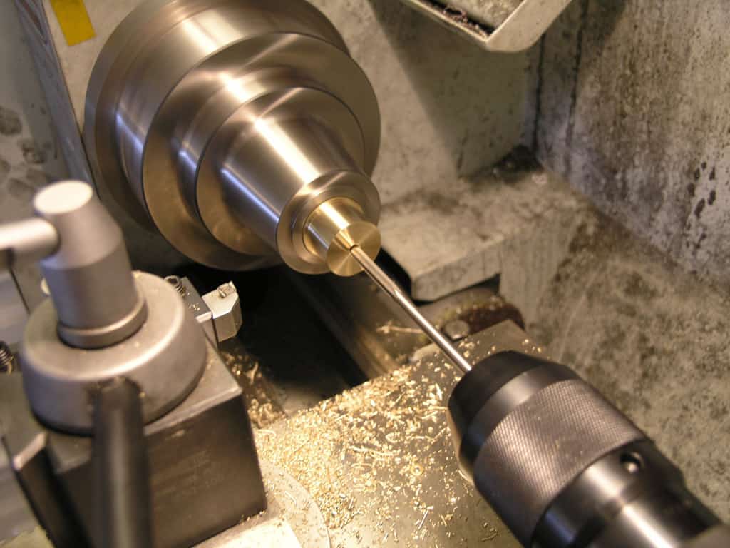
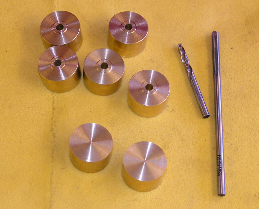
Next I am using a screw machine-length twist drill for the shaft bore. The screw machine length is more rigid than normal jobber length and with a minimal facing nub you can go right in without a center drill, thus saving a step...

Ream the hole after drilling...
Cut Shoulder
Note: If I had to make another 12, I would not do this step here. Once the overall slug has been turned and faced to length (see way down below, I do actually do this on one), the collet stop lets us do one shoulder, and then flip around to do the other without resetting the depth of cut. That's faster!

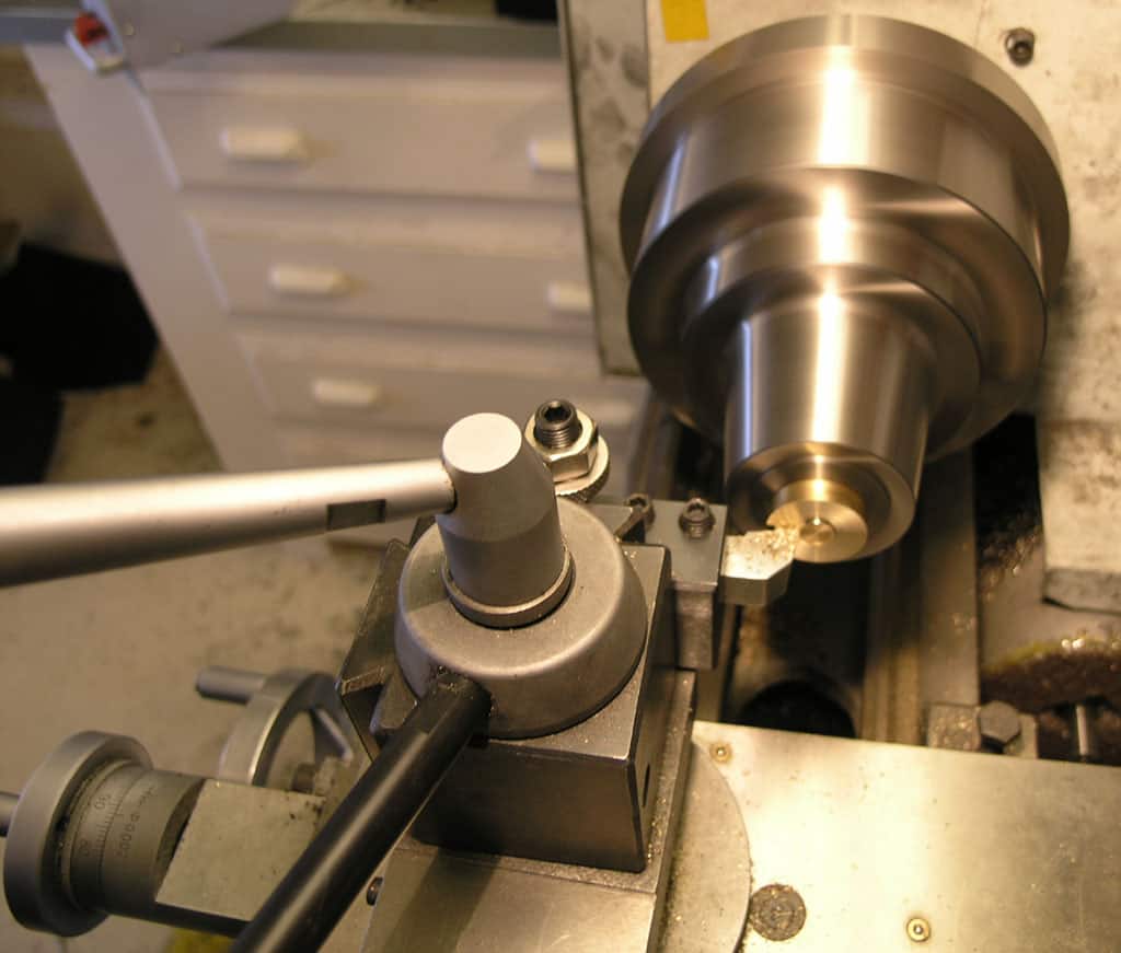
Next up: cutting the shoulder for the hub. This will be a little facing cut that doesn't go all the way to the center. To start, go back and just touch the cutter to the face gently...

Zero your compound DRO. What's that, no compound DRO? Well, I made mine just for this project, but I can tell I'll use it a lot!

Pull the cutter back with the cross slide dial and set the depth of cut with the compound. I want a 0.156" shoulder, so I dial that in as best I can on the compound...

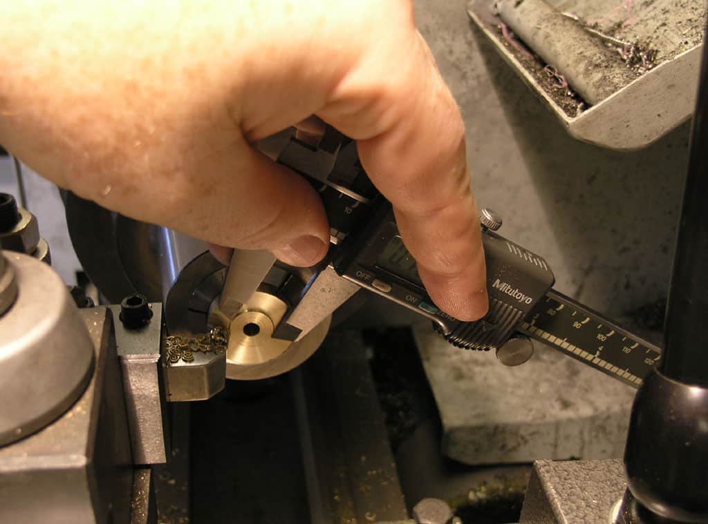
The first time through, I stopped a couple of times and checked with the digital calipers to see what the diameter of the hub was...

After that first time, I knew what the cross slide dial should read ("50" for this part). You can tell by looking which revolution to stop at that dial number on. Goes really fast that way!
Deburr With File
Forgot to take a picture, but the last step before removing any part from the collet is a little deburr with a file. The reason is so that when you flip the part around there is no burr to interfere with the accuracy of the collet.

That part is ready to be removed...

3 Flywheels were finished during experimentation. The rest await flipping around to do the back side...
Flip and Part Off the Excess

For this phase, a collet stop figures into our plans...

The stop screws into the rear of the collet positively locates one end of the workpiece...

I measure how far inside the stop is using my compound DRO. Touch off the end of the collet, and set to zero. Insert a workpiece against the stop, tighten, face, and using the DRO, measure by touching the face of the workpiece. In this case, my stop is 0.404" inside the collet from the lip...

Now I insert the workpiece into the collet, tighten, and touch off the lip with my Aloris parting tool...

Zero the DRO at the touch off point...

My workpiece will be 0.6562" in length when finished. I took the 0.404" inside the collet plus 0.290" for the parting off. That will give me 0.694". I want the extra slop because I'll need to face the surface. The part off doesn't leave as nice a finish...

Now with the carriage locked, I'll go through and part all the pieces to length. I was able to turn the crank as fast and hard as I could with one hand and they parted beautifully. Note: this is not the most accurate of operations. Why? Because the collet moves in and out as tightened. The good news is I used pieces already finished to very close to the same diameter, +/- 2 or 3 thou, and tightened to about the same torque. I'll do a check and see how close they are in length...

The result of parting. We'll clean that up with a facing cut after we've run all the parts through...

Here we are all parted. Note there is a variable amount of the larger diameter material left, but not very much. Also note the lower right part has no shoulder. I had to remake one of these due to an error on the first one. I decided it was faster to do both shoulders last because I can just flip the part once the shoulder cut is set up and do both shoulders at once.
Flip, Face, and Shoulder
The next step is easy. We're going to flip the part around in the collet, face it to exact length, and then put the little shoulder on the flipped side.
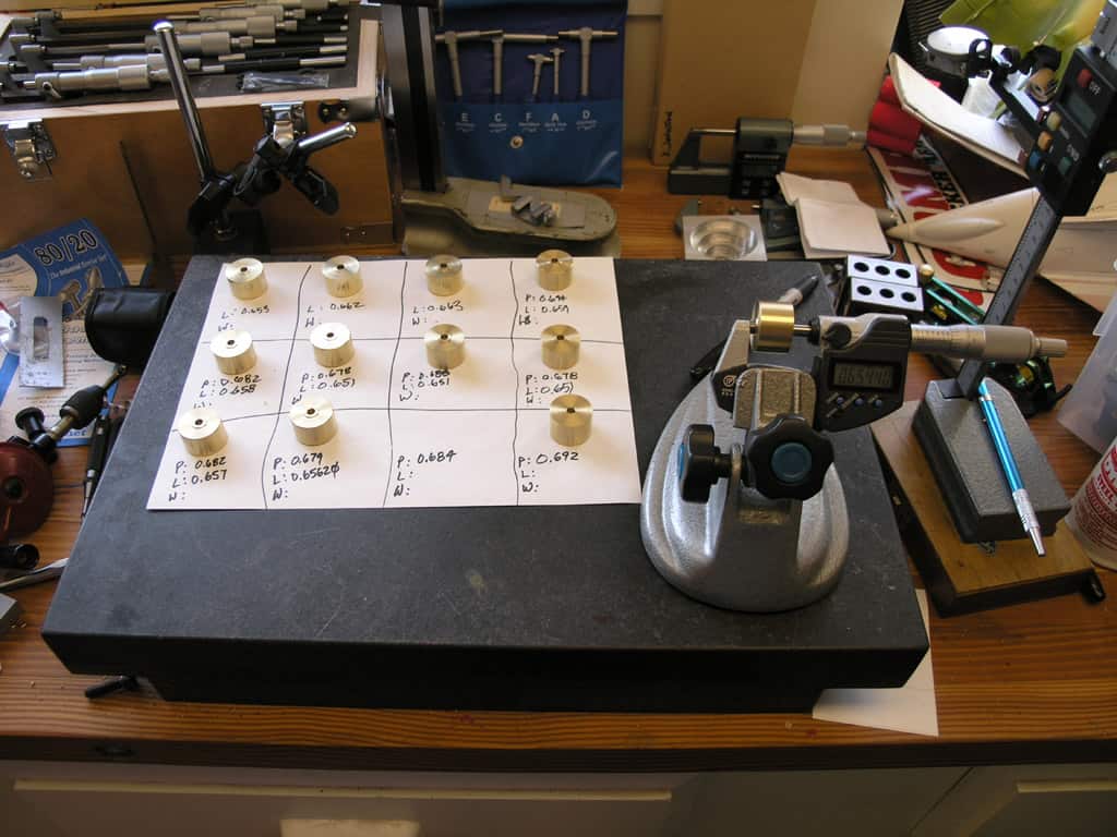
Here's my little inspection area on the surface plate. I'm measuring each part's width with the mic and noting under the "P". It should be 0.6562", so the difference tells me how much to take off when facing...

Insert the part in the collet against the stop, start the spindle and "touch off" with a piece of paper. To do this, place the paper between the spinning work and the tool and slowly advance the tool until it just grabs the paper. You should be within 0.001" of the part. Zero the compound DRO...

Dial in the desired cut to make the part 0.6562"...

And face to length...
I experimented with paper touch offs as well as just gently touching a non-moving workpiece. The paper touch off was more accurate (after allowing for 0.001" paper thickness). Something to keep in mind...
Cut the shoulder from this zero point another 0.0156" until the cross slide dial reads "50" on the right revolution and we're done!
The parts are now dimensionally correct!
Set Screws (aka Grub Screws overseas)
Plans call for a 5-40, so I have the proper set screws and a couple spiral flute taps on order from Enco. I'll be using collets on the mill to line things up.
Experiments Before Flywheel Production
I thought it a good idea to try a few things along the way rather than just diving into production. My goal was to learn some new things and come up with a better mousetrap for cranking these things out. If you've never had to make more than one of a part, it's an interesting pastime to try to put together your optimum assembly line process.
Before starting, my plan to make each flywheel was this:
- Turn the OD on my brass stock down to 1" diameter and polish with brass polish. I'll do this turning between centers.
- Part off the individual flywheels.
- Face each end in a chuck and put the 1/64" shoulder on while facing. Polish the shoulders, but leave the facing stock from shoulder to end of flywheel with a matte finish. Perhaps a little coarse emery.
- Bore and ream the 3/16" hole.
- Take to the mill and drill and thread the 5-40 set screw hole (grub screw for those across the pond).
A concern I had is the close fit 3/8" hole. I planned to ream the hole. Looking at some helpful information from Yankee Reamer, I conclude that for a tolerance of 0.0005", I want to ream 0.0003-0.0004" below the finished size. 3/8" = 0.3750", so I want a reamer that is 0.3746 - 0.3747" in diameter. That sounds like an undersized 3/8" to me.
Further, they suggest the reamer should be removing 0.007 to 0.015" of stock, which means I want to drill an initial hole that is 0.3676 - 0.3732" in diameter. They suggest an oversize allowance of 0.0048" for the drill bit. Hence, we want a drill bit that ranges from 0.3676 - 0.0048 = 0.3628" to 0.3732 - 0.0048 = 0.3648". That's going to be a "U" sized drill whose diameter is 0.3680".
If I leave 0.1" on either side of the rough stock, I get a total width for the rough stock of circa 0.860". If I choose to do 4 flywheels per piece of stock, I need 3 pieces of brass round stock each 3.5" long.
Turning Brass to 1.000" and Polishing

I started out by sticking the brass stock in my 6-jaw and putting a quick center drill hole there for the tailstock. Boy, I sure like having a keyless chuck and a tailstock cam lock to make stuff like this go really fast!

What the heck is going on here??? That rig is called a "Constant Face Turning" setting. Sometimes just "Face Turning". The stock is held by my favorite Royal live center in the tailstock, and driven by a special center on the spindle that is hydraulically sprung against the stock and is equipped with teeth that give it traction on the stock. I found it on eBay for $75, a cheap Asian knock off of a type of tooling that costs big bucks for the pro stuff and is regularly used with CNC. You know me: I love gadgets! This one is really much nicer than fooling around with lathe dogs to drive the work. You get access to the full length this way. Here's another view of the face turning rig stopped from my vise stop project:

Another view of the constant face turning head...

I'm doing several experiments on the project. For example, I start out turning with my CCMT turning tools until I get things into reasonable shape. Also, I wanted to see how close I could come to holding 1" along the entire 8" length of this brass cylinder by tuning up the lathe tailstock set over, and then by hand tuning the dial while the feed was in motion. Such accuracy is not needed for the flywheel, but these are experiments I like to do as I go to stay in practice or learn something new.

What I'm doing here is cutting a bit, measuring the taper with a micrometer (I have both vernier and digital and make myself use the vernier for the first 5 or 6 measurements on a project before I go to my Mitutoyo digitals. That's just to stay in practice), and tweaking the tailstock until I got the tailstock end to be smaller than the headstock end. That's as much as you can do adjusting the tailstock set over. When was the last time you adjusted yours?

Once I got happy with my taper adjustments, and I got the shaft a lot closer to 1" in diameter (I was about 0.050" over), I pulled out my HSS steel finishing cutter. It has a big radius and a sharp edge. Folks say it leaves a nicer surface finish. I think the latter is very slight compared to my CCMT's, but it is discernable, so why not use the HSS? Isn't it nice to cut brass? So shiny! So easy!

Okay this one is tricky. Remember I said I would tweak the dial during the feed to offset the taper? I mic'd both ends after a shallow (0.005") cut. I determined that based on the taper I was seeing (0.003" over 8"), I could turn the dial by eye a little less than half a division each 1/4 of the shaft length. I performed my final pass while doing so, and then mic'd the resulting 1/4 sections of the shaft. You can see my results rounded to the nearest thousandth though my mic reads to 1/10 of tenth. Not too bad. The second quadrant I was a little too aggressive and it's 0.999". The leftmost quadrant I was a little late and was 0.001" too big at the end. I know exactly how both happened. On the second quadrant, I got confused about diameter versus radius (move the dial 0.001", did diameter reduce 0.001" or 0.002"). Things were moving too fast and I'd never tried this. I knew as soon as I'd done it I went too far. So I slowed up to try to compensate on future turns. On that 4th quadrant (leftmost), I was lagging it and hence was 0.001" over. All in all, I rate this as not bad for a first try. As I said up front, the little flywheel doesn't need even a thou of accuracy on its diameter. This was just a random exercise in precision to sharpen my skills and try a new technique. You'll notice also no use of calipers! I went back with my Mitutoyo calipers and it would be easy to conclude the whole shaft was dead nuts on with them. Calipers are not precision instruments, micrometers are!
Next up is to polish...

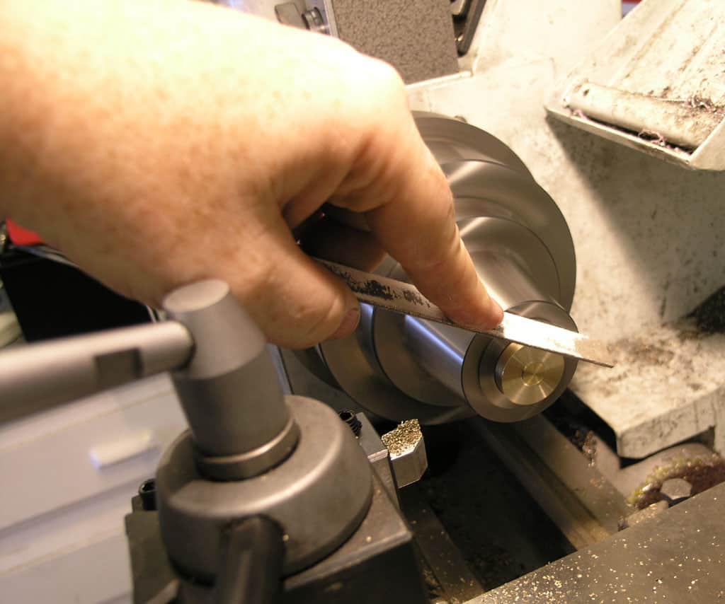
I'm starting with 150 grit aluminum oxide paper. This grit is only slightly finer than the toolmarks, and should not be used for very long or you'll take off too much material...

Here is the aftermath of 150 grit.

Next up is some 220. This is a lot nicer grit. In future, I'd be tempted to forget the 150 and start here as it leaves a nicer finish. 220 is a good match for what a lot of folks call a "satin" finish...

There's a 220 grit finish. Note the cross hatch. Those are the marks left by the 220. Anything else is a scratch that has to be removed by the 220. Still a couple here, so I kept on going...

My next grade of sand paper was 1500. That's pretty darned fine, but still not a mirror finish....
Next up, Brasso Polish...

For the final "mirror" finish, many folks swear by Brasso. I thought I had a nifty idea. Lautard likes to run sandpaper up and over a file to use it on a lathe. I bought some cheap synthetic chamois to use with the brasso. Bad news: I got scratches and had to drop back to my 220!

I thought the file was messing me up, so I tried it with a piece of MIC-6 plate. Still got rude scratches! Back to 220 again and starting to loose confidence in Brasso...

Aha! When used with a paper towel, the Brasso finally shines it up! Seems my cheap chamois had grit in it. I would sure hate to use that on a car's paint job!

Here's my project box where I keep everything I'm using on this project. I have the plans, the polished brass cylinder, and an extra piece of rough brass stock....
Stopped Here to Get Collet Chuck Installed
Unfortunately, I needed to take a little detour at this point to make a backplate for my collet chuck. Important Collet Tip:
Use your file to knock the shoulder burr off before removing the part from the collet. The part wont seat accurately in a collet with that shoulder burr there after facing! I can't tell you how many times I pulled the part out and had to put it right back in to take that burr off. Develop the habit!
Using a small chalked file to knock the shoulder burr off before removing the part from the collet...
Back On Track
For this batch of flywheels, I am following the plan and cutting slugs to length on saw, facing to exact length, drill, ream, add the little shoulders.
Drill and Ream the Bore

I go in with the center drill, then the twist drill, and finally the reamer to clean up the hole. This is pretty fast with my camlock tailstock and keyless chuck...

First the center drill, then the twist drill...

...and the reamer finishes up the bore...
Cutting the Shoulders

To cut the shoulder, I zero the tool by touching it to the work face and zeroing this crude DRO. Then I crank the tool back out of the way and turn the compound dial until the DRO reads how much I want to take off...
I then take that cut...
I know how far to go because I used my calipers on the first one...

Then I noted where the dial should wind up when I was done with the shoulder. Fast and easy!
What We Got
Minor Rework on A Few Outliers With The Polishing Rig
To polish, I'm going to suspend the flywheels between two centers. The falderoll at the top of starting from finished stock was a losing proposition because the collets do mar the finish. Apparently you can purchase nylong 5C collets to avoid this. In my case, I simply switched over to a polishing rig that makes it pretty easy. That rig involves suspending the part between two centers. I use a dead center in the collet chuck to drive the part and a live center in the tailstock.
As I was inspecting parts, I noticed a couple of outliers that had diameters more than 5 thousandths off the 1.000 spec, so I decided to see if the polishing rig would fix that up.
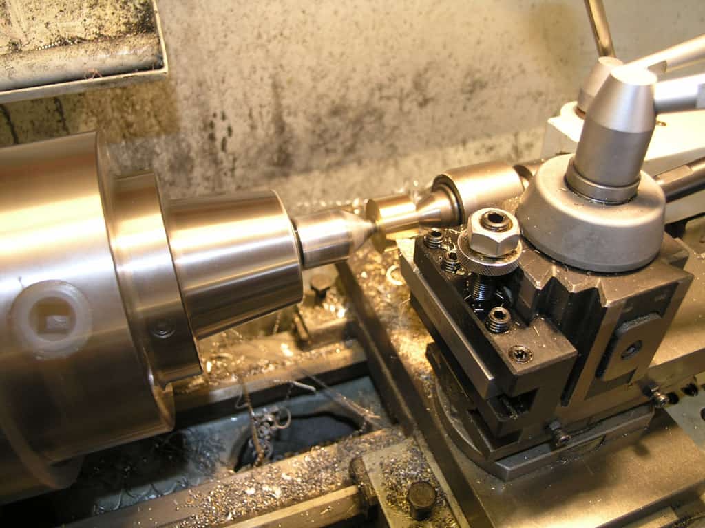
You can turn off up to 0.002" without slipping by using a sharp insert and reasonably tight pressure on the tailstock ram...

This procedure is not only useful to rework small parts like this, but it leaves a pretty darned good finish to start from in the polishing process...
Be the first to know about updates at CNC Cookbook
Join our newsletter to get updates on what's next at CNC Cookbook.