This project is from many years ago, soon after I got my small lathe. The parts aren't as finely finished as I would make them today, but the tailstock is highly functional and a significant improvement over the original bolt that required a wrench to lock.
I've always wanted a camlock tailstock for my Lathemaster lathe, similar to the Little Machine Shop kit for mini-lathes. However, the LMS kit is designed for 7×14" lathes and doesn't fit the Lathemaster. Adapting one is possible, but after reviewing the parts and installation instructions, I realized it's straightforward to make one from scratch for my lathe.
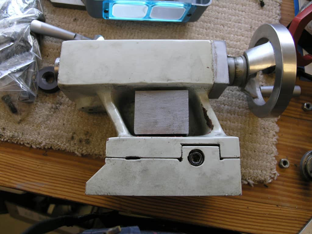
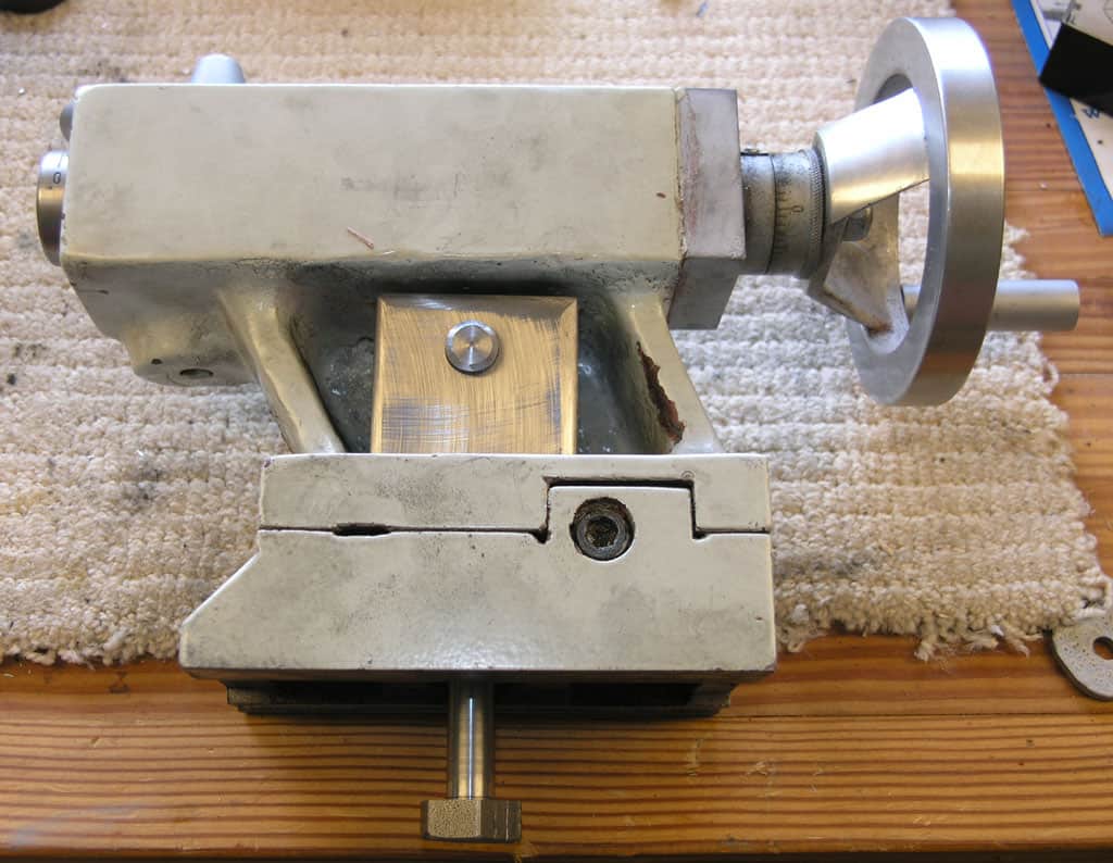
The Finished Product
It's good to see where you're going with this:
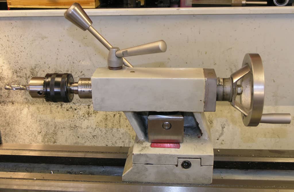
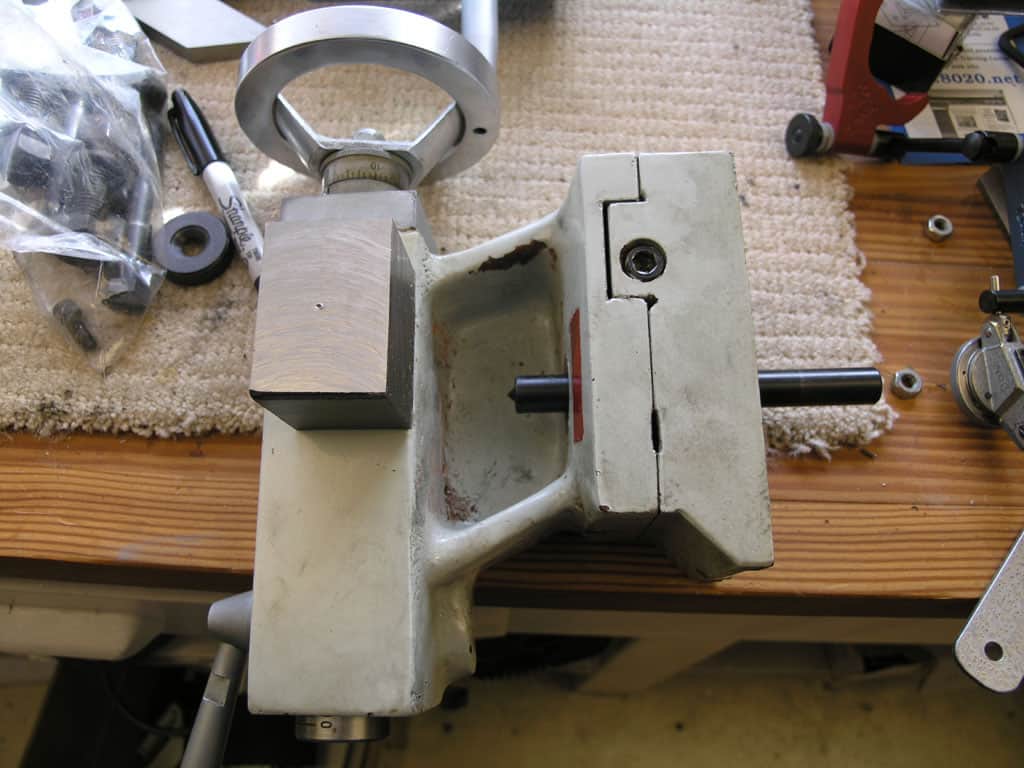
Installed on the Tailstock. No more wrench!
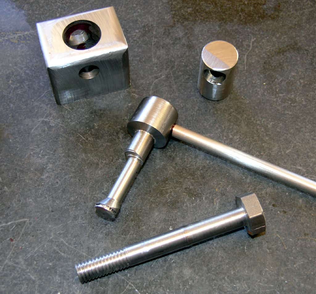
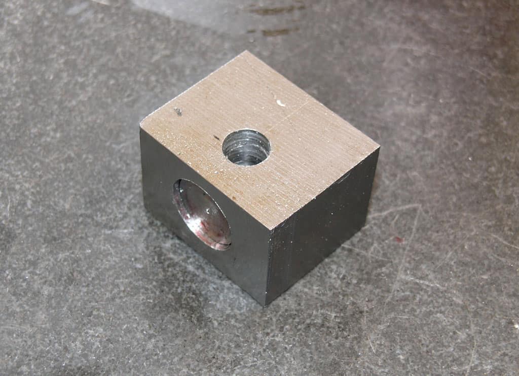
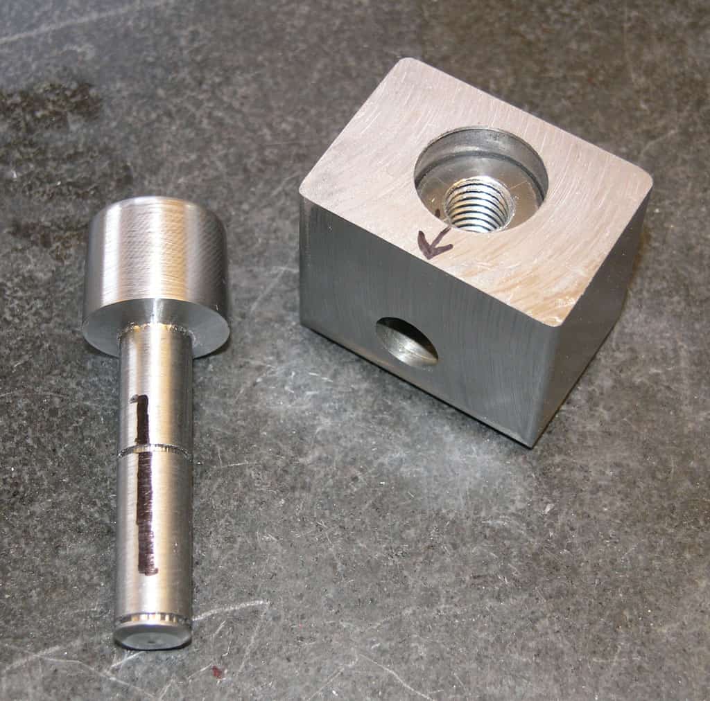
The parts: frame block, locking piston, camshaft with lever, and locking bolt...
Checking how much locking motion the cam must provide
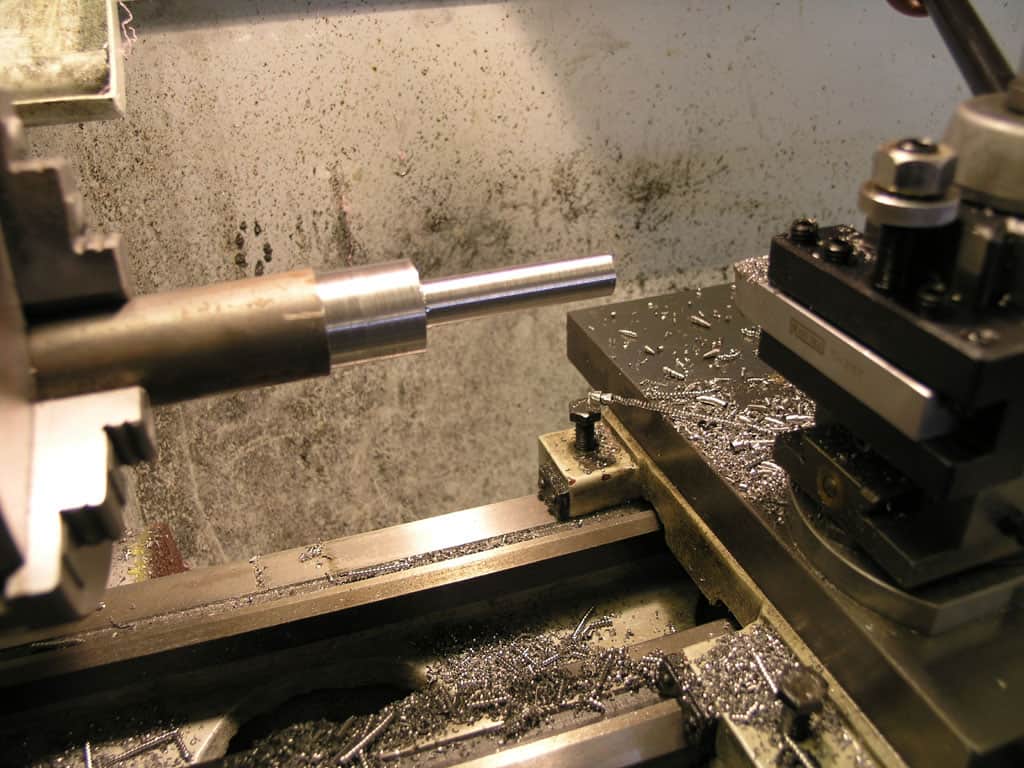
I started out looking at how the existing lock works. I determined by measuring a couple of photos that the action of the nut moves the locking bolt something on the order of 0.15":
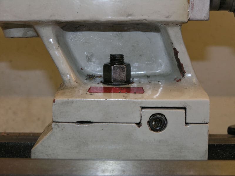
Bolt with tailstock unlocked...
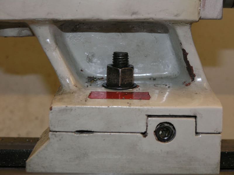
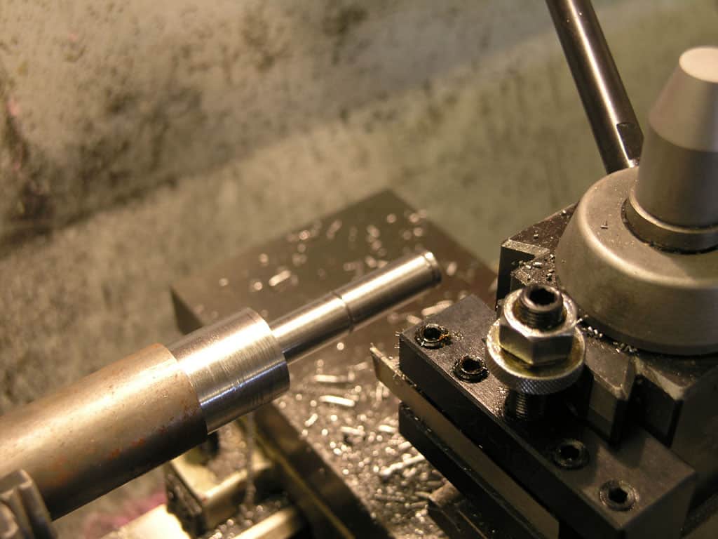
Locked tailstock. The motion required is about 0.150". I'll try to allow for as much as 0.200" travel...
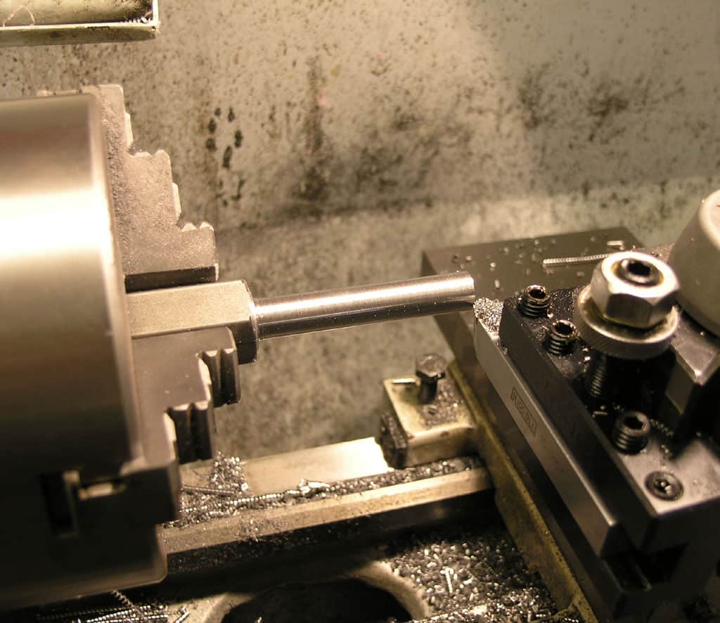
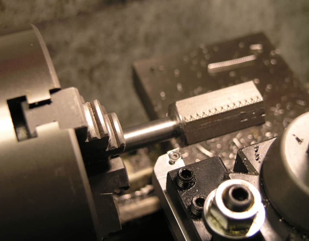
Making the camlock camshaft
I decided to make the camshaft 1/2" diameter, with an arbitrary larger diameter that will be used to mount the operating lever. This is an easy turning job...
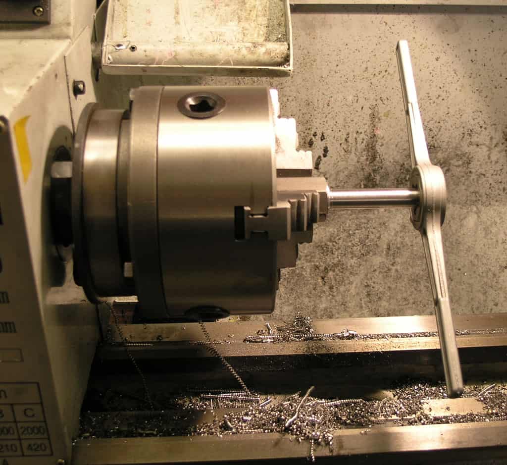
Next, I used my parting blade to put in a couple of grooves for snap rings to go on either side of a frame block. I doubt I'll use the inner ring, but the outer ring will hold the operating lever in place so it can't be pulled out.
Making a Frame Block
The purpose of the frame block is to sit inside the cavity of the tailstock and stabilize the cam action from rocking. I cut a piece of square stock to approximately the right size...
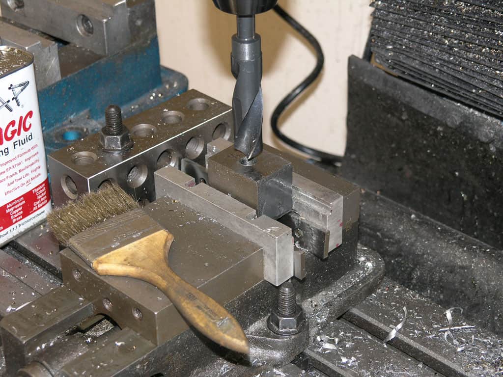
Then I used a 1/2" transfer punch to locate the hole for the tailstock locking bolt on the frame block...
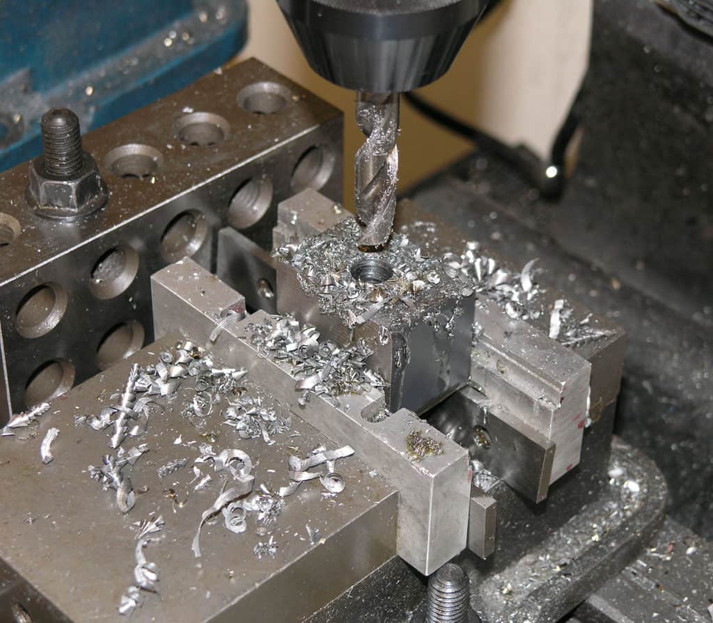
I drilled a 1/2" pilot at that point on the milling machine...
Then I bumped up to a 7/8" Silver & Deming bit. This is the largest size I thought I could drill for the cam piston bore and still leave enough meat on the frame block to act as a proper pivotig hub for the camshaft...

Having completed the piston bore, I used the height gage to mark out the centerline of the piston bore so I could center the cross hole for the camshaft properly on the piston bore...
Making the locking piston
The locking piston is just a cylinder turned to fit the 7/8" bore of the frame block. Here I am testing the fit. I have not yet drilled that camshaft cross bore.
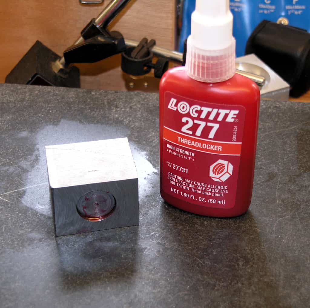
The reason being I wanted to Loctite the piston into the frame block and drill the camshaft crossbore through both as a unit, ensuring a good fit. Loctite will release with temperature, so I will be able to get these two apart again...
Got a 1/2" cross bore through the frame block and the actuating piston. Now a little butane torch warm up and a rap with a brass punch and hammer and I'll have these two back apart easily...
You'll notice in later pictures that I ground all faces and rounded the edges on the frame block using my 12" Disc Sander...
Making a New Locking Bolt
The tailstock locking bolt that comes with the lathe uses a metric thread. Not having a set of metric taps, I simply made a new bolt in 1/2"-13 so I could thread the piston and get on with the project.
I started out with some hex 12L14 stock which I turned down to the 0.4500" diameter needed for this thread...
I then threaded it with a die...
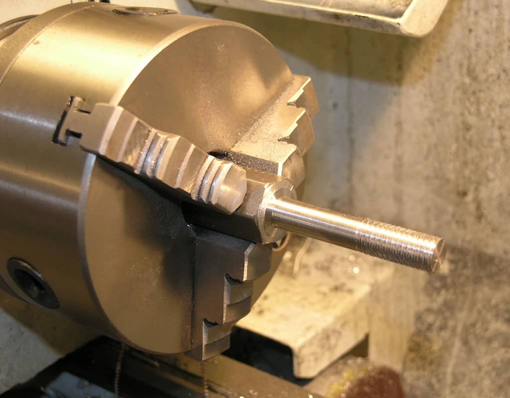
Looks clean. Next step is to flip this piece around and finish the other end...
For this operation I'll be cutting away from the headstock to a shoulder at the end. Note: I started off with a "pretty close" piece from my stock. If you start with a longer piece, you wouldn't need to flip it around. I just didn't have enough to grip in the chuck. Also note that I wrapped the threads with a little piece of sandpaper before sticking them back into the chuck to protect them...

Working up to the shoulder with multiple passes. I didn't grip the other end terribly tightly in the chuck because I didn't want to risk damaging the threads, so I'm taking it easy here...
Threading the Piston for the Locking Bolt
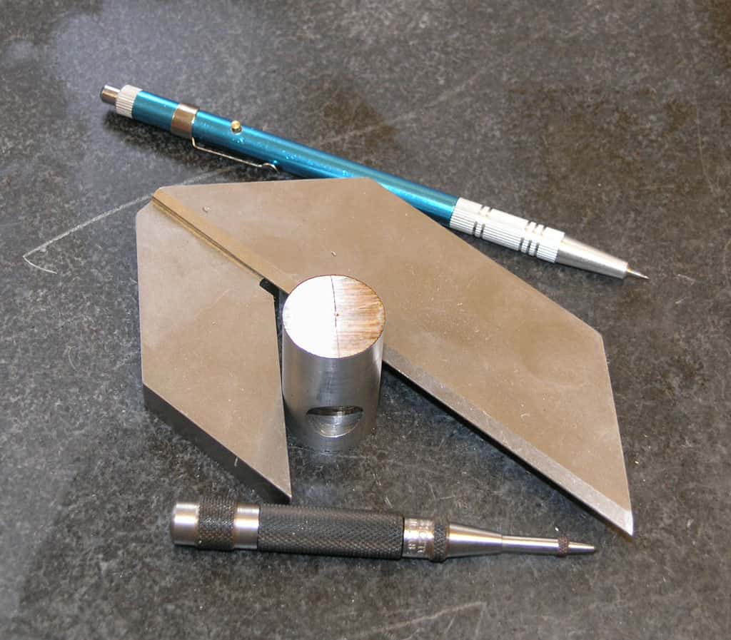
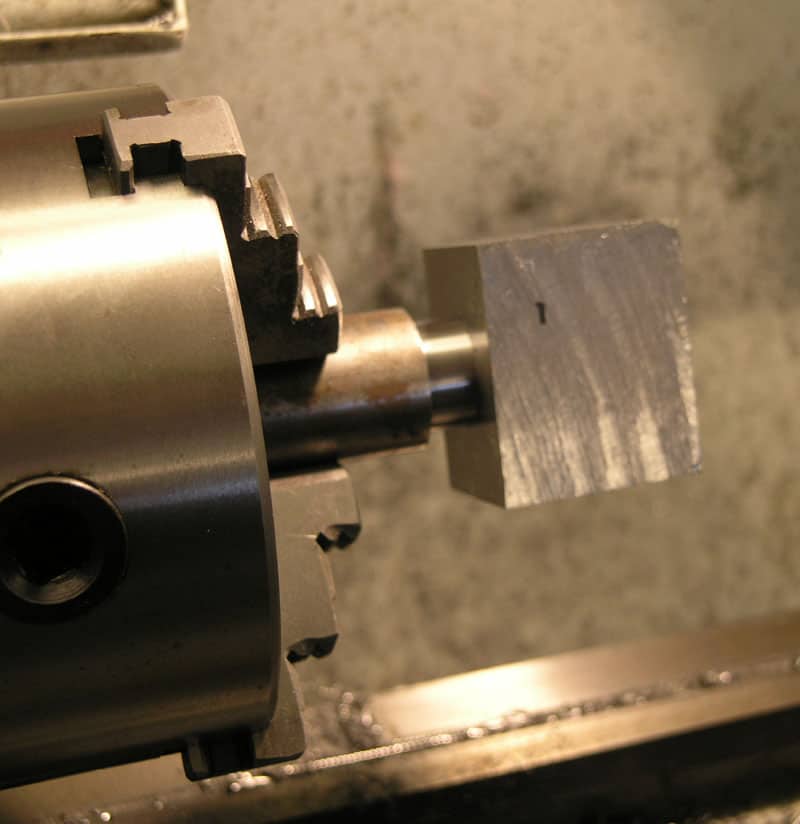
That big crazy shaped gadget is for marking the center on round stock. I used the carbide scribe to mark two radials and then my Starrett automatic punch for the center. After that I drilled the requisite hole for a 1/2"-13 thread and used a tap to thread the piston...
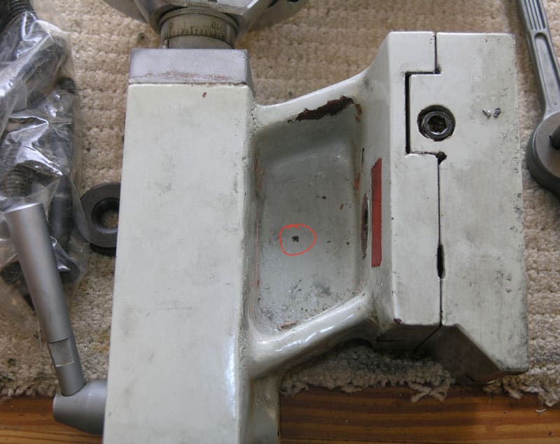
Drilling the Tailstock to Mount the Camlok
At one point it would have made me squeamish to drill a hole in one of my machines, but no longer:
Using my 1/2" transfer punch and locating the piston with the bolt, I mark where to drill. Since I only have two hands and I'm taking a picture, I can't hold the piston and block in their proper position flush against the bottom of the tailstock, but rest assured I marked the hole in the right place!
It goes right about there. I can't believe I forgot to take pix of the process, but I did. Got to excited I guess! Basically, I clamped the tailstock on the mill. I supported the ram housing on a 1-2-3 block and then used varying sizes of parallels under the base until I had it oriented so the hole would be perpendicular to the ways. The cast iron the tailstock is made of cuts very nicely. No real drama there.
And here is a trial fit up. We are on the right track!
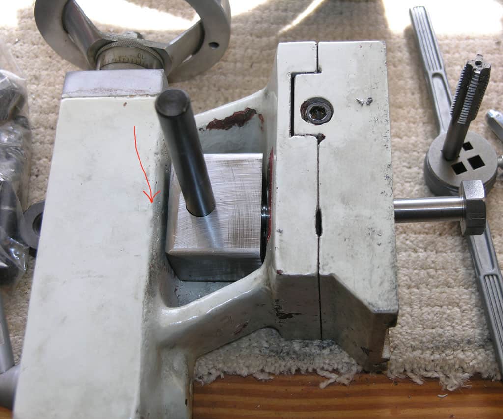
Making the Offset Cam
This is probably the most sophisticated piece of machining in the whole project. I wanted to machine the cam section of the camshaft so that it was as wide as the locking piston, but no wider. This way the frame block can support the camshaft in the 1/2" hole.
First step was to mark off how long the cam section needed to be. I measured back from the front (outward facing portion) of the frame block. I also marked block and piston to keep straight the orientation. Note that the piston isn't centered on the block due to the shape of the tailstock cavity.
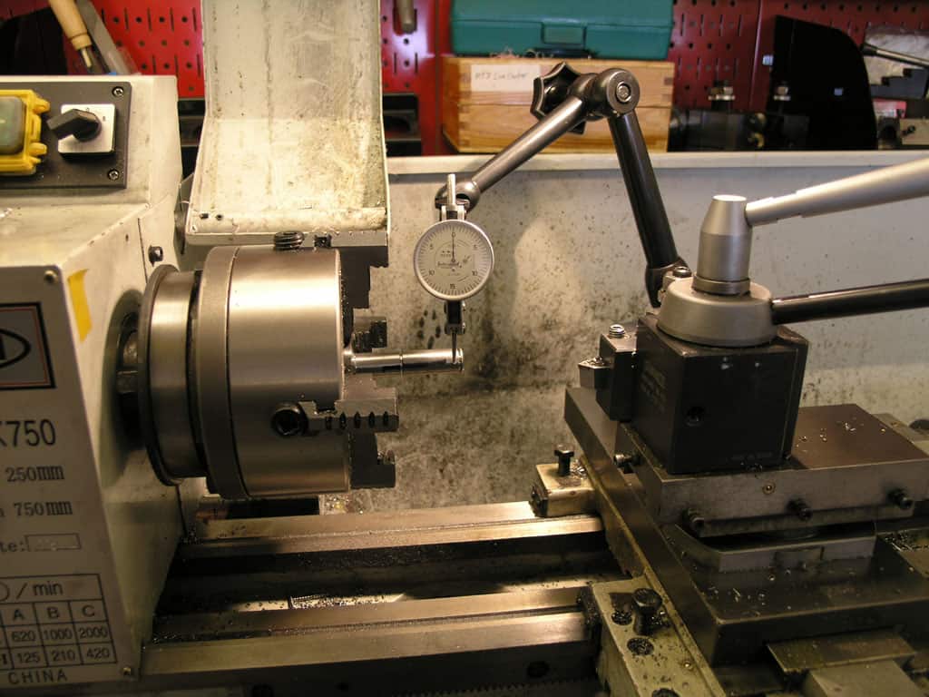
Next I dialed in the camshaft on my 4-jaw. Then I used the dials to move my indicator out to an 0.2" greater diameter. I wanted to have 0.2" of travel when the cam operated. Lastly, I used the 4-jaw chuck jaws to move the workpiece until it just registered again on the DTI. Now the piece is offset 0.200" in the 4-jaw and if I turn it, I'll be cutting an eccentric...
Making a Handle for the Lever
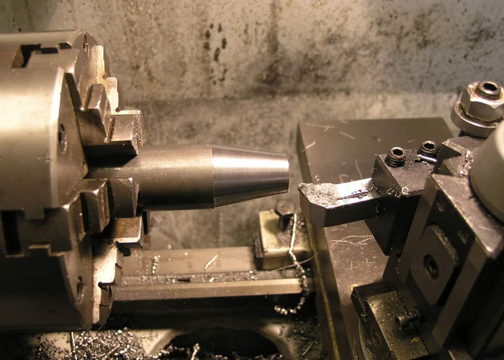
With the compound at an angle, you can make some interesting shapes...
Now the top angle gives us a little gearshift knob shape...
All Done, Let's Try It Out!
There's the eccentric as well as the rest of the components of the project. I "glued" the lever into the camshaft using Loctite. I chose the angle for the hole by eyeballing where I wanted the lever to be when the cam was in the "locked" position.
There it is in action! It works amazingly well with very tight clamping action with the lever to the left, and complete freedom to slide the tailstock with the lever to the right. You'll need to adjust it by tightening the bolt as tight as it can be with the level in the unlocked position and still be able to slide the tailstock.
Things I Would (and May Yet) Change if I Did it Over
- I was worried about keeping things together and properly positioned in the tailstock cavity. That just doesn't look like a problem. I don't think I need even a locking snap ring, for example.
- I was concerned about the shoulders on the cam and their fit relative to the piston and frame block. Too little cam and the piston will be caught on the shoulders and won't move. Too much and the cam will flop around in the frame block. After having Loctited the lever, I left the assembly for the night fully intending to machine a new cam with better shoulders the next day. However, when I tried this cam, it worked extremely well. I don't know if I'll ever get around to making a new one. If I were to do so, here are some thoughts. First, there's no need to dial in the stock to start. Chuck up some round stock and get it close to centered by eyeball. Turn the concentric parts of the shape, but don't part off. Now set the part offset 0.200" using the method I describe. You can dive in without having to first center the part because it is centered by virtue of the earlier turing operations. Think about how to get a nice shoulder on the cam with your tooling. I had my part to far inside the jaws and had to come in from an angle which spoiled by chances of a shoulder.
- The handle would be nicer if it canted out away from the tailstock instead of being parallel. There's room for it, but you'd have to unlock it to work the ram locking lever, for example. Another approach would be to just make it a lot shorter. I made it pretty long because I didn't know how much leverage I would need. I will likely shorten it if I get comfortable with the idea though the length actually keeps the knob from interfering with the ram locking lever.
- I'm debating whether to go back in and blue the parts. They match the lathe better as they are, so I probably won't.
Be the first to know about updates at CNC Cookbook
Join our newsletter to get updates on what's next at CNC Cookbook.