Editor's Note: I made this Kurt Vise Stop LONG ago and in a galaxy far away. I bring it back to the forefront because it is an extremely useful tool.
Why Use a Vise Stop?
Vise stops allow you to position a part in a precise location in your machinist vise every time. They can save on setup for machining multiple identical parts because you drop the part in the vise, slide it against the stop, tighten the vise, and you're ready to machine each new part.
I use mine every time I use my milling vise. I have this rule that I won't take a part off my machine until I am sure I can put it right back in exactly the same place. You'd be amazed at how much time this has saved me over the years for what little time it takes to set the stop before removing the part.
Making my Kurt Vise Stop
This project is based on a milling vise stop made by "Widgitmaster", who may be found on the CNCZone. When I saw it, I knew immediately that it would be a handy gadget to have around as well as an excellent project to help me explore the capabilities of my new Industrial Hobbies mill further. The original Widgitmaster creation looked like this:
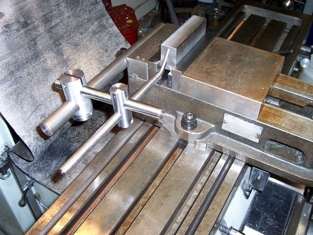
Widgitmaster's Kurt Vise Stop in Use...
As you can see, it's a handsome and very straightforward design. I thought I would add a small embellishment in order to personalize my version in the form of using split cotter clamps with knurled finger wheels rather than the allen held clamp arrangement in the original version. I watch guys using milling vise stops pawing around for the right allen wrench or whatever, and I just smile. It's so much easy to give this stop a finger tight twist and the cotter clamps put serious leverage on the stop so it can't move anywhere.
I'm just going to present the highlights here, rather than a step-by-step construction article.

Design and Drawings for Kurt Vise Stop
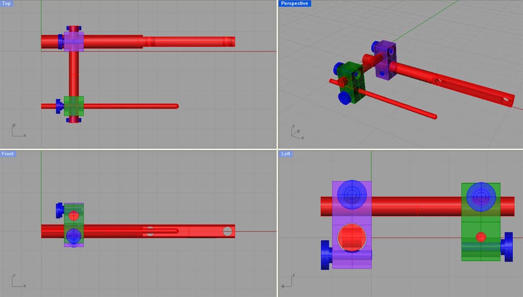
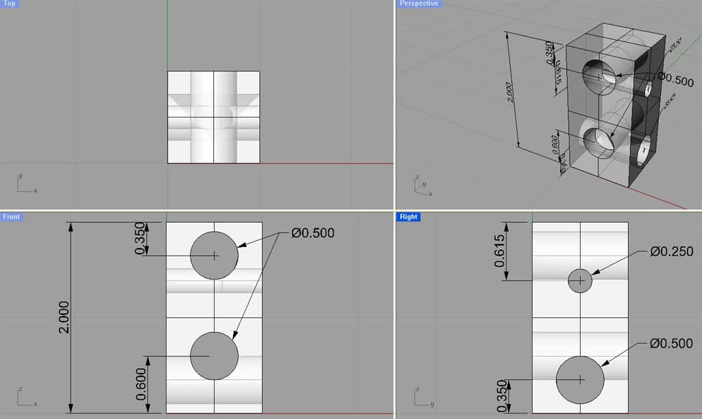
Here are 4 views of the basic concept...
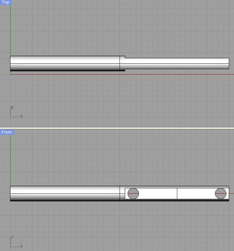
I made my rear bar 0.770" diameter because that's what fit the hole my 3/4" Silver-Deming bit made in the clamping block. YMMV. Also, check the holes in the back of your vise carefully. Mine looked like they were on 4" centers, but it's actually slightly less. I wound up milling the end hole into a short slot to make due. It wasn't off by much, but just enough to be annoying.
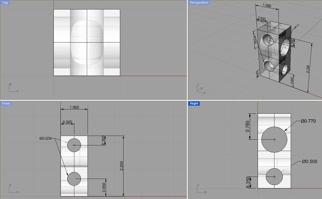
Rear Clamping Block
The clamping blocks are hole drilling exercises, but the holes overlap for the split cotter, so you have to lay them out and drill them precisely! Also, don't just dive into these unless you understand how to machine the split cotter. See my note below for details, but you will be drilling the shaft holes with the cotter cylinders in place in order to cut the little crescents out of them in one operation.
Front Clamping Block
I am using progressively smaller rods as we move from the rear rod (bolted to vise), to the cross rod, to the stop rod. The rear rod is 0.770" in diameter. The cross rod is 0.5" in diameter. And, the stop rod is 0.25" in diameter. You will want to round the end, or perhaps point the end of the stop rod so it can act as a precise stop.
Lastly, check below for a drawing of the cotter cylinders. You will need to make up 4 of those.
Constant Face Turning: How to Teach an Old (Lathe) Dog New Tricks
When it came time to turn the bigger bar that attaches the stop to the vise, I decided to try a piece of tooling that's been sitting in the corner of my shop for some time. It's an Asian imported constant face turning rig that I bought from an eBay seller called "800watt". I'm not sure whether they are still available-at the time nobody seemed to have any idea what one was and I got it cheap, being the only bidder. The idea is pretty simple. You're turning between centers, but the driven center operates by using teeth to engage the workpiece. A little hydraulic force gives it some spring load as well:
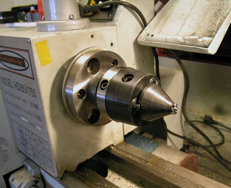
Constant Face Turning: The Business End...
The advantage of this rig is you can access the entire length of the workpiece without any waste. So, I chuck up my workpiece in the 6-jaw, faced and center drilled both ends, and then popped it into the constant turning rig to see how things would go:
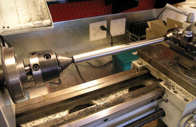
It's all there baby!
You can see here I had already milled the flats on either side and drilled the holes to mount the bracket to the Kurt vise. It was nice to be able to turn the whole thing for a nice finish in one shot. This sort of thing, albeit fantastically more expensive and sophisticated, is used in industry quite a bit. If you can reduce the number of setups or waste with such a thing, you'll make a lot more money on your job. In theory, the most accurate way to turn is between centers, and it is also important to turn between centers if you need to take the part off the lathe and put it back on while maintaining concentricity.
I don't know how often I'll use the face turning rig, but I was feeling very happy to have tried it when I finished fooling around with it the other night. Here are a couple of links that provide more information if you are curious about face turning:
And speaking of gadgets, another great tool is the collet block (at least they are if you have a set of collets to go with them!):
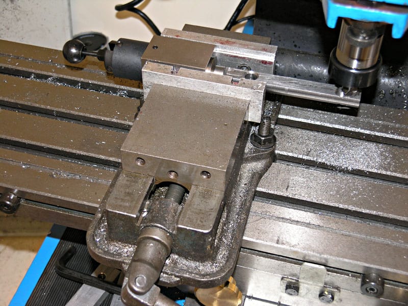
Using a collet block to hold the rear bar while I make one of the 2 holes a slot to allow greater range of freedom on the bar...
They make it easy to grip round stock for milling, and they're indexed so I can just flip the square block over to access the other side of the bar and make sure everything I do is parallel to the first surface. A set of collets are pretty expensive, but collet blocks are cheap.
Making the Split Collet Clamps for the Kurt Vise Stop
These are interesting little clamps that take a little ingenuity to make. Guy Lautard details them in his Machinist's Bedside Reader, Volume 1 book. Their chief virtues are twofold. One, they are just neat little gadgets that one can take pride in crafting. Two, they convert a very little finger pressure into a whole lot of clamping force. These two qualities made them seem idea for this project.
They can be made with just an Allen-head bolt, or with the knurled finger screws such as I am planning. One more quality-many clamps require a slitting saw so there is "squish room" as the clamp is tightened. These clamps do not.
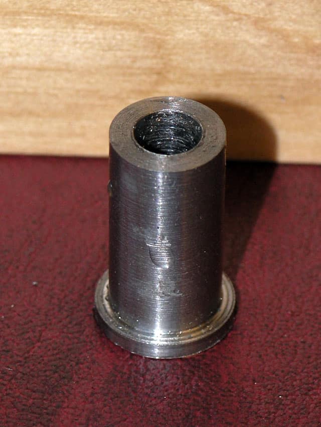
Here is the basic barrel you need to turn on the lathe to get started with one of these:
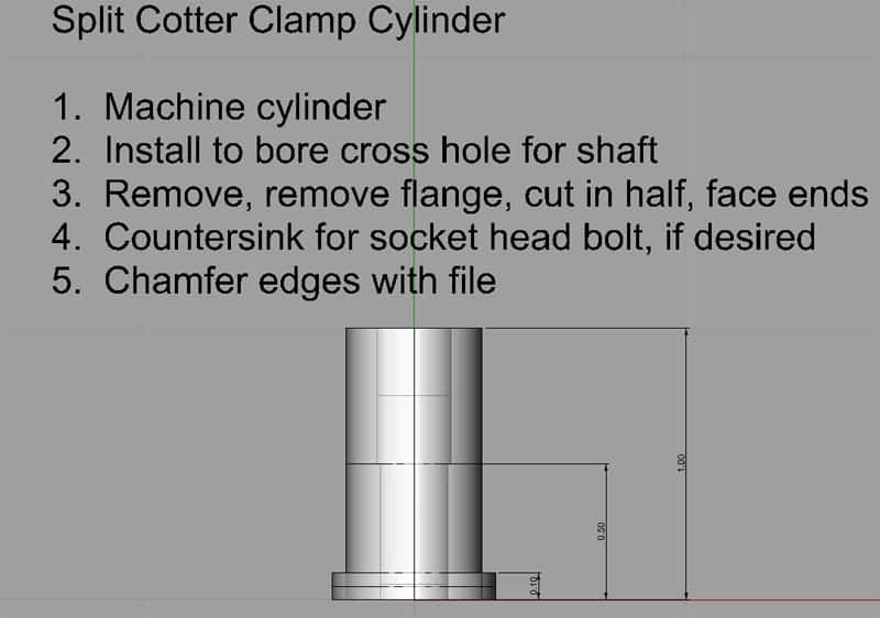
As you can see, it's a pretty simply little widget to make on a lathe:
Flange OD and shoulder turned. Center drill and then drill the two diameters...
Can't resist a shot of my favorite QCTP tool: Aloris carbide insert parting off tool...
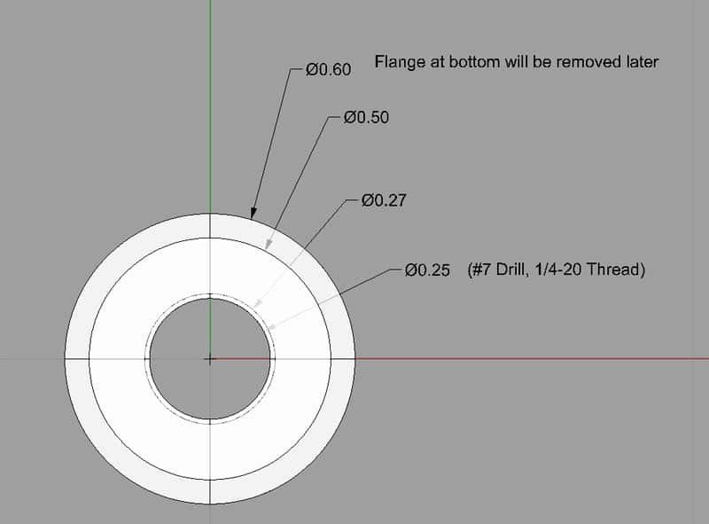
I turned my stock to 0.600" OD, turned down the end to 0.500" to create the flange shoulder, center drilled, drilled a #7 hole (recommended size to tap for 1/4-20) full length, and then a slightly larger 0.27" hole for half the length, starting at the non-flange end. Parted it off, filed the parting flash, and voila:
Cylinder with flange...
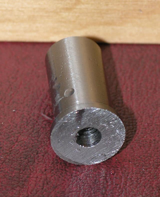
More cylinder with flange...
Tapping it...
Now that you've made your cylinders, and I just cranked out all 4 at once while I had things set up and convenient, it's time to make the clamping blocks that hold the cylinders.
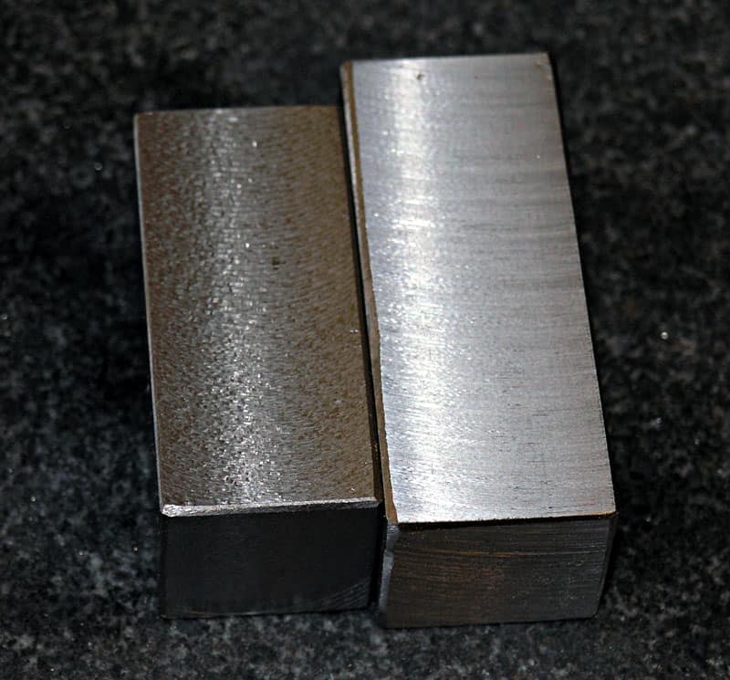
First, I squared up the blocks using 2 different cutters so I could compare their performance. Block on left is a 6-flute corn cob hogger. Block on right is a flycutter with brazed carbide lathe tool. More info on my surface finish page.
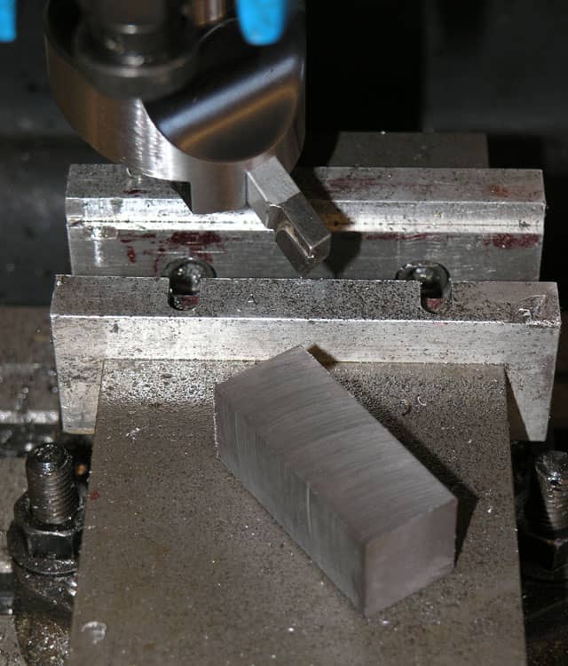
Just finished squaring the larger rear block with my flycutter...
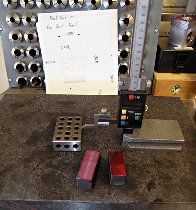
Next step is layout. Blocks have been blued (er, redded?) with Dychem, and they're sitting on my surface plate. Got the prints in back.
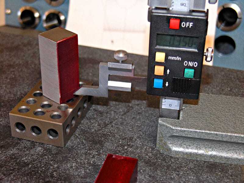
I'm measuring for hole centers from the two ends, just like the prints are marked. Height gage and surface plate make this so easy!
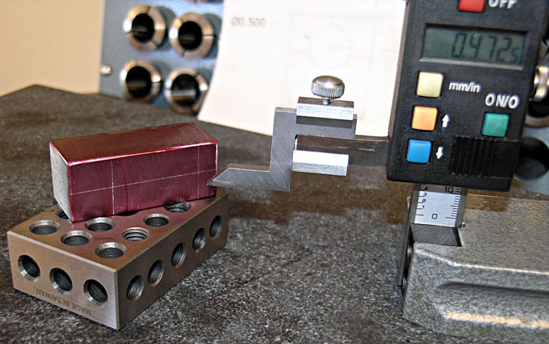
Now we scribe the center line. A light tap with a centerpunch and we're done laying out the block...
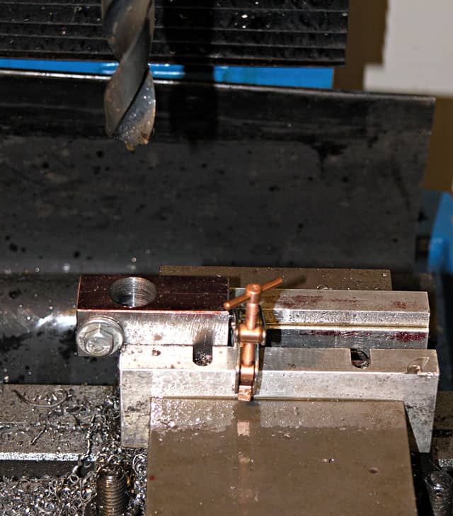
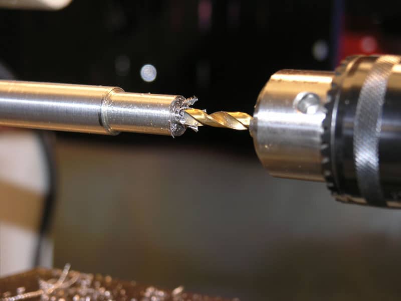
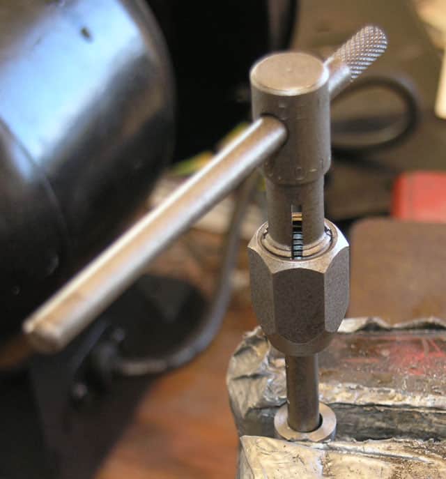
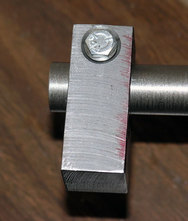
Several things to note. First, the improvised milling vise stop using a Kant-Twist clamp. It lets me remove the block from the vise and get it back into exactly the same position. Second, the split cotter barrel is bolted into it's hole in the block. We're busy drilling the big hole for the shaft using a Silver&Deming bit in my Lathemaster Keyless Chuck...
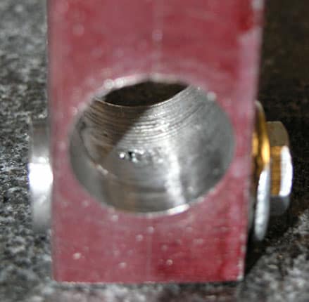
See the oval in the wall of the big hole? We've cut the split cotter barrel to exactly the right shape by having it bolted in there...
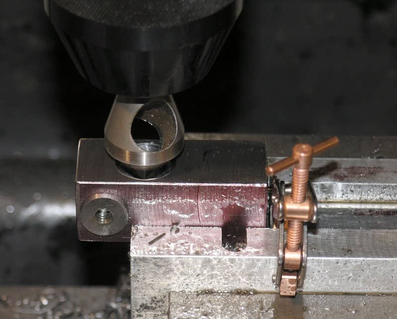
Now we can pop the block back into the vise, having checked it for fit, and it goes right back to the same place due to my simple kurt vise stop. I am deburring and chamfering the hole with a Zeo Zero Flute Deburring Tool.
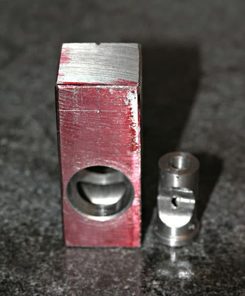
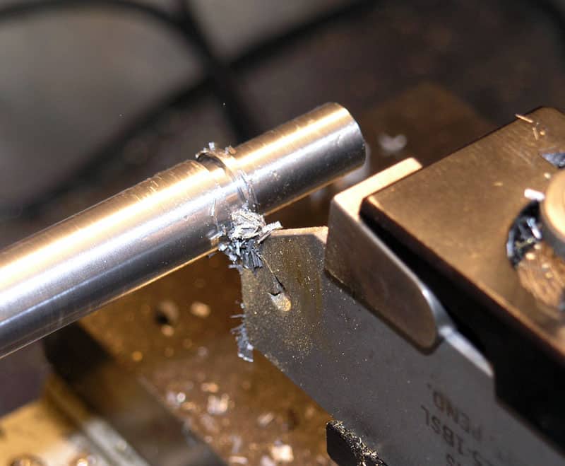
One cotter, needing to be split and a perfect couple of bores to use it in. I popped the cotter in the lathe, turned off the flange on the bottom, rounded the end, and then used my Aloris part off tool to split the cotter.
Using a temporary bolt, I tested it. Split cotters have a very tight grip on the shaft with very little tightening force required. As such, they're ideal when a small knurled clamping knob is used. This one works great. Now I have to do 3 more!
I turned some knurled finger wheels on the lathe real quick and easy to use with the clamps. I don't have drawings, photos, or narrative on them. They're dead easy to make and I did it entirely by eye without making any measurements except a swipe with the calipers a couple of times to make sure the threaded portion would be the correct diameter for the 1/4-20 thread I had planned. My trusty tailstock dieholder facilitated the threading operation. I made them from brass, which is a material I love both for its good looks and ease of machining.
So, without further fanfare, here is the finished result of my tinkerings:
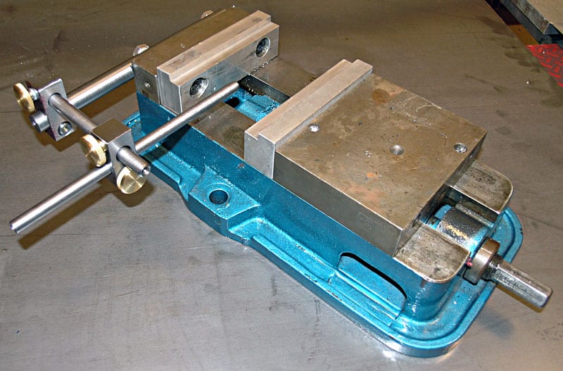
The completed Kurt vise stop on my 6" Kurt Milling Vise...
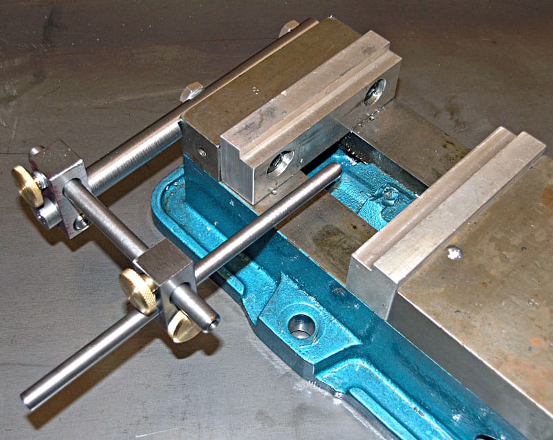
Slightly closer view of Kurt vise stop...
Having discovered the joys of a milling vise stop (remember my improvised Kant-Twist clamp mentioned above?), I am looking forward to using this beast. My chief disappointment is that I should have made at least one more. This was for my 6" Kurt Vise, but my favorite vise is a 4" Kurt, and the hole centers are different.
What would I do differently the next time? Well, Widgitmasters uses the slit sawed style clamp, but I really like the split cotters, so I wouldn't change that at all. I believe the biggest thing I would change would be to use all the same diameter shafts. On the first iteration, I made each shaft a little smaller. It made sense to me at the time, but if they were all the same it would make the task of building one of these widgits simpler and faster. So, that's what I'll be doing when I make the stop for the 4" vise.
Enjoy, and give thanks to the Figditing Widgitmaster who put me onto this concept in the first place!
Back to Milling Machine Home...
Be the first to know about updates at CNC Cookbook
Join our newsletter to get updates on what's next at CNC Cookbook.