During my search on Google to understand the workings of pneumatic indexing tables, I found an explanation of face gear rotary tables. These tables are highly sturdy but are restricted to halting at secure spots on the circle, such as every five degrees. They usually employ pneumatic mechanisms and some are managed by turning a switch located on top of the table (without any rotation of the spindle) using the CNC spindle.
The face gear mechanism works by meshing two face gears using axial movement. As the gears move closer to one another they are forced to engage precisely:
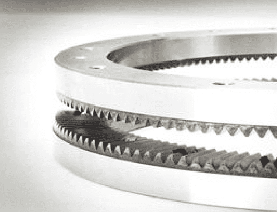
Face gears are also referred to as "Hirth" gears. Here is another example:

Advancing to a new index point consists of the following steps:
- Unlock the face gears by moving them apart.
- Rotate to approximately the right position. "Approximately" means close enough that when the face gears are locked up again the teeth will force the final correction to make the position exactly right.
- Lock the face gears by moving them together. This will nudget the shaft into the precise desired position and once locked will keep it there with great rigidity.
The big advantage of these face gear mechanisms is rigidity. The disadvantage is they only move in fixed increments. Because of this, they're most useful for indexing work to fixed positions. One of the most common uses in machining is to use a Hirth Gear to lock a lathe turret in place when a new tool is indexed into position. Another would be to create a horizontal tombstone arrange to increase the parts capacity of the machine:

Here is a spin indexer converted for use as a CNC 4th axis using a step motor and right angle drive:
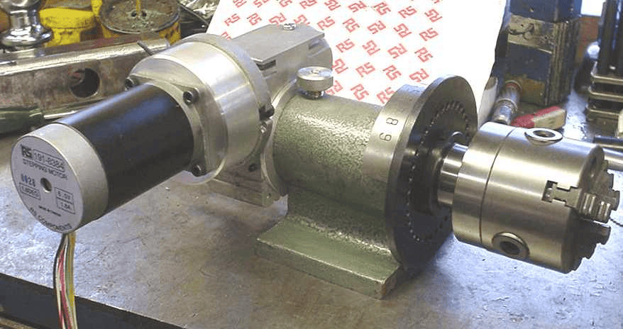
Indexers like these have very limited rigidity, especially if you are machining near the edge of the chuck which puts leverage to work against the rigidity of the indexer. The usual answer to this problem in commercial gear is to provide a pneumatic friction lock (basically, a disc brake) to help lock the axis. While a disc brake is not as rigid as a face gear system, it allows the system to be locked at arbitrary index positions instead of at fixed degree intervals. For more on disc brakes, check out our 4th axis disc brake article.
Be the first to know about updates at CNC Cookbook
Join our newsletter to get updates on what's next at CNC Cookbook.