Introduction to Tool Compensation in CNC Machining
CNCCookbook’s G-Code Tutorial
The Concept of Cutter Compensation (aka Tool Compensation)
The G41 and G42 G-codes are specifically designed for tool radius compensation in CNC machining operations.
Cutter compensation is a fundamental concept in CNC machining that involves adjusting the tool path to compensate for the size and shape of the cutting tool being used. Every cutting tool has a specific radius, which affects the accuracy and precision of cuts.
When Cutter Compensation is active, the programmed cutting point is the edge of the cutter. When it isn't active, the programmed cutting point is the center of the tool.
The Significance of Cutter Compensation in Achieving Accurate Cuts
Accurate cuts are essential in CNC machining as they directly impact the quality and functionality of machined parts. Cutter compensation plays a vital role by allowing operators to account for tool wear, deflection, and varying geometries.
Because Cutter Compensation allows programming of the cutting edge and not the tool centerline, these adjustments or offsets make it possible to adjust cut paths or shift coordinates. This enables operators to maintain consistent tolerances throughout production runs.
This level of precision is crucial when manufacturing intricate components where even slight deviations can lead to critical failures or poor performance.
Introduction to G41 and G42 Codes as Tool Radius Compensation Commands
G41 and G42 are G-codes specifically designed for tool radius compensation in CNC machining operations. These codes instruct machines to adjust the programmed path based on offset values associated with specific tools' radii.
G41 represents left-hand side (LHS) compensation while G42 represents right-hand side (RHS) compensation. When using G41 code, the machine automatically shifts the programmed path to ensure that it lies outside (to the left) of the actual cutting location by an amount equal to the radius value assigned to that particular tool.
Conversely, with G42 code, the machine compensates by moving inside (to the right) of the actual cut location by an amount equal to its assigned radius value. Tool radius compensation codes like G41 and G42 are indispensable in achieving accurate cuts, minimizing programming errors, and simplifying the machining process.
They aid in reducing machine downtime, enabling faster production speeds, ensuring better surface finishes, and extending tool life. Understanding the nuances of these codes is vital for CNC programmers and operators seeking to optimize their machining operations.
Exploring G41: Tool Radius Compensation Left
Detailed explanation of G41 code functionality
G41 is a tool radius compensation command used in CNC machining to achieve accurate cuts by compensating for the tool's radius. When this code is activated, the control system offsets the tool path to the left of the programmed path by an amount equal to the radius of the cutting tool.
This ensures that the cutter follows a path that corresponds precisely to the intended shape or contour, taking into account any material removed by the cutting edge. The G41 code is typically accompanied by additional parameters such as D (tool diameter) and H (offset value).
The D parameter specifies the diameter of the cutting tool, while H represents an offset value indicating how much material should be removed from the part. Together, these parameters help define and control the compensation process accurately.
How the left-hand side cutter compensation works
When using G41 with left-hand side cutter compensation, every point on the programmed path is offset towards its left. This means that if we imagine a line representing our intended path, we will see that our actual cutting position lies exactly on this line but slightly shifted to its left side. To better understand this concept, consider an example where you want to cut a circular pocket with a diameter of 50mm.
By activating G41 and providing appropriate parameters like D50 (tool diameter) and H0 (offset value), your machine's controller will offset all points on your programmed circle 25mm to their left. As a result, you will achieve an accurately cut pocket with a 50mm diameter.
Practical examples showcasing application of G41 code
One practical application where G41 proves valuable is when machining complex contours or profiles with inside corners. Let's say you're manufacturing a customized gear component which involves milling teeth. By utilizing G41, you can maintain precise dimensions by compensating for the tool's radius when machining the internal corners of each tooth.
This ensures that the gear will fit seamlessly with other mating components. Another instance where G41 finds relevance is in contouring operations involving non-circular shapes, such as designing decorative or ornamental patterns on surfaces.
With G41 in action, you can achieve smooth and accurate cuts without worrying about the tool's radius distorting or altering your intended design. In both cases, G41 minimizes the need for manual corrections and reduces time-consuming iterations while guaranteeing high precision and quality in your machined parts.
Unveiling G42: Tool Radius Compensation Right
In-depth analysis of G42 code features
The G42 code is a vital component of CNC machining that facilitates the right-hand side tool radius compensation. When this code is employed, the CNC machine automatically adjusts its cutting trajectory to account for the tool's radius on the right side, ensuring precise and accurate cuts.
This compensation helps prevent errors such as excess material remaining after a cut due to an inadequately accounted for tool radius. G42 differs from its counterpart, G41 (Tool Radius Compensation Left), in that it accounts for the right side of the tool.
By specifying G42 in the G-code program, machinists instruct their CNC machines to offset their cutting paths by precisely half of the tool's diameter towards its right side. This adjustment ensures that the desired part dimensions are achieved by compensating for any inaccuracies introduced by tool geometry.
Understanding the right-hand side cutter compensation method
Tool radius compensation on the right-hand side involves accounting for a milling cutter's geometry when making cuts along specific paths. Once enabled with G42, the machine will automatically offset all programmed positions by half of the cutter's diameter towards its right side during cutting operations.
This adjustment ensures that each cut accurately represents intended dimensions and contours without any deviations caused by incorrect positioning relative to the desired cut path. The CNC machine interprets and implements G42 commands efficiently when provided with accurate input parameters.
To enable proper right-hand side compensation, machinists must specify either an R value or an H value after calling G42 in the program. The R value denotes exactly half of the milling cutter's diameter, while an H value represents an explicit radial offset distance from a reference point or previous position.
Real-world scenarios demonstrating utilization of G42 code
To illustrate how extensively employed the G42 code is in CNC machining, consider the manufacturing of complex components like gears or circular profiles. In such cases, using G42 allows machinists to accurately produce these shapes by compensating for the tool's radius on the right side. Without this compensation, discrepancies between desired and actual dimensions may occur, leading to improper gear meshing or flawed circular profiles.
In addition to gears and circular profiles, G42 finds application in various scenarios where right-hand side tool radius compensation is necessary. For instance, when machining intricate parts with tight tolerances that require precise contours or fillets, G42 ensures that every cut maintains accuracy and consistency throughout the process.
By adopting this code correctly, machinists can minimize errors and achieve high-quality finishes while producing components that adhere closely to design specifications. Overall, G42 plays a crucial role in CNC machining by enabling right-hand side tool radius compensation.
Its implementation ensures accurate cuts and precise part dimensions in real-world applications such as gear manufacturing and complex component fabrication. By understanding its features and applying it appropriately in different scenarios, machinists can leverage the power of G42 to enhance their machining processes significantly.
Differences between G41 and G42 Codes
Comparative analysis between left and right-hand side cutter compensation
When it comes to tool radius compensation, G41 and G42 codes play a vital role in CNC machining. While both codes serve the purpose of adjusting the cutter's path to account for its size, they do so in different directions. The G41 code is used for left-hand side cutter compensation, while the G42 code is employed for right-hand side tool compensation.
This distinction affects the direction in which material is removed during cutting operations. In left-hand side cutter compensation (G41), when the cutter moves along an inside contour, the programmed path is offset to the left by a distance equal to half of the cutter's diameter.
This adjustment ensures that the desired part dimensions are achieved while compensating for the cutter's size. On the other hand, right-hand side cutter compensation (G42) shifts the programmed path to the right by half of the cutter's diameter when cutting along an outside contour.
Advantages and disadvantages associated with each code
One advantage of using G41 (left-hand side cutter compensation) is that it allows for tighter tolerances on inside contours because material removal occurs on the opposite side of the programmed path. This reduces wear on cutters and minimizes any inaccuracies caused by deflection or vibration during machining. Conversely, employing G42 (right-hand side cutter compensation) offers benefits when working with outside contours.
By offsetting towards the material being removed, it helps prevent excess stock from interfering with subsequent machining operations. However, it's important to note that tight inside corners may pose challenges due to potential over-cutting if not properly programmed or compensated.
Examples illustrating when to use either G41 or G42
To better understand when to use each code, let's consider a practical example. Suppose you are machining a circular pocket with an inside contour and an outside contour.
In this case, G41 would be the appropriate choice when roughing out the pocket, as it ensures accurate dimensions on the inside edges. On the other hand, during finishing passes along the outside contour of the pocket, G42 would be more suitable since it prevents excess stock from interfering with subsequent operations.
Another scenario where these codes come into play is when creating slots or keyways with a milling cutter. For instance, when cutting an internal slot, using G41 compensates for tool radius on the left-hand side of the programmed path to achieve precise dimensions.
Conversely, when machining an external slot or keyway, G42 compensates for tool radius on the right-hand side to prevent excess material from interfering with subsequent steps. By understanding these differences and considering specific machining requirements, operators can select between G41 and G42 codes to optimize cutter compensation and achieve accurate results in CNC machining processes.
Machining Considerations with Cutter Compensation Codes
Impact on part geometry due to tool radius compensation
When implementing tool radius compensation with G41 and G42 codes, it is crucial to understand the impact it has on part geometry. Tool radius compensation allows the CNC machine to adjust the toolpath based on the actual size of the cutting tool used. With G41 (left-hand side) or G42 (right-hand side) active, the machine offsets the programmed path inward or outward by half of the tool's diameter, resulting in accurate cuts.
One significant consideration is that tool compensation affects both internal and external contours differently. When compensating for an internal contour, such as a pocket or hole, using G41 (left-hand side), the offset can cause a tighter fit between the machined feature and its mating parts.
On the other hand, when compensating an external contour with G42 (right-hand side), there may be a slight gap between machined components due to material removed during machining. Furthermore, it is essential to consider how multiple passes impact part geometry when using these codes.
If not properly programmed, excessive material removal during each pass can lead to oversize dimensions or even irregular shapes. It is crucial to carefully plan and test multi-pass strategies while taking into account factors like feed rate, depth of cut per pass, and material properties.
Tips for efficient programming using these codes
Efficient programming with G41 and G42 codes involves understanding various techniques and implementing best practices for optimal results. Firstly, it's recommended to use CAD/CAM software that supports automatic generation of tool radius compensation codes based on part geometry.
This ensures accuracy while reducing manual coding efforts. Another tip is to carefully select appropriate cutting tools with accurate dimensions provided by manufacturers.
Using precise measurements allows for more predictable adjustments during compensation. To ensure efficient execution of these codes, it is essential to calculate and set correct tool offsets before initiating the machining process.
This involves accurately measuring the tool's radius and inputting the appropriate value into the machine's control system. Additionally, implementing a thorough testing and validation process is critical.
By simulating toolpaths through CAM software or utilizing machine simulation features, programmers can identify potential issues before actual machining. This helps avoid costly errors and minimizes material waste.
Common errors and troubleshooting techniques related to these codes
Despite careful planning, certain common errors may arise when working with G41 and G42 codes. Understanding these pitfalls can help programmers troubleshoot issues effectively. One common error is forgetting to cancel compensation after completing a profile or contour.
Neglecting to turn off cutter compensation (G40) can cause unintended adjustments in subsequent toolpaths, leading to incorrect dimensions or improper fitting of machined components. Another mistake is neglecting to define correct initial cutter paths for sharp corners or small radii.
If not pre-programmed properly, these areas may contain unwanted material resulting from compensation adjustments. It is crucial to use efficient programming techniques such as lead-in/lead-out moves (G01) or using smaller offset values around tight corners.
In case of unexpected results during machining, troubleshooting involves verifying that all parameters such as cutter diameter offset values (D), heights (H), and initial coordinates (I/J/K) are correctly inputted into the program. Overall, by being aware of potential errors, understanding their root causes, and having effective troubleshooting techniques in place, CNC programmers can ensure smooth execution of G41 and G42 codes while minimizing downtime associated with debugging issues during production runs.
Advanced Applications and Variations of Cutter Compensation Codes
Tool Nose Radius Compensation (G40)
Tool nose radius compensation, represented by the G40 code, is a powerful feature that allows CNC machinists to account for the shape of a tool's cutting edge. This compensation ensures precise machining by offsetting the programmed tool path based on the tool's nose radius.
By using G40, machinists can accurately machine intricate profiles and maintain consistent part dimensions. One common application of G40 is in contour milling.
When machining curved surfaces or intricate geometries, tool nose radius compensation enables operators to achieve smooth finishes while compensating for the tool's geometry. By utilizing this code, machinists can program sophisticated shapes without having to manually adjust for the tool's dimensions.
Furthermore, G40 becomes particularly useful when working with tools that have varying nose radii or complex profiles. By applying different values for tool nose radius compensation during a single operation, machinists can effectively control how much material is cut and ensure accurate machining across various features on a workpiece.
Programming Techniques for Complex Geometries using Multiple Codes (G41/G42)
When dealing with complex geometries that require intricate cuts or sharp corners, employing multiple codes such as G41 and G42 becomes essential. These codes are used in conjunction with each other to compensate for both left-hand side (G41) and right-hand side (G42) tool movements while machining.
To program complex geometries using G41/G42 codes, careful consideration needs to be given to each segment of the cutting path. Operators must ensure that they correctly alternate between G41 and G42 at appropriate points during the operation.
By properly utilizing these codes in conjunction with suitable lead-in and lead-out moves (using linear interpolation), precise control over corner radii can be achieved without sacrificing surface finish or part accuracy. It is crucial to note that programming complex geometries using G41/G42 requires a deep understanding of the tool's geometry, part design, and the desired result.
It may require iterative adjustments and fine-tuning until optimal results are obtained. However, with patience and attention to detail, machinists can leverage these codes to produce intricate parts with remarkable accuracy.
Extending Functionality with Additional Parameters (D, H, I, J, K)
In addition to the standard G41/G42 codes for tool radius compensation, several additional parameters can be utilized to further extend the functionality of these commands. These parameters include D (cutter diameter offset), H (tool length offset), I/J/K (incremental values for arc centers), and more.
The D parameter allows machinists to specify an offset value that represents the difference between the actual cutter diameter and its nominal size. This compensates for cutter wear or replacement with tools of different dimensions while maintaining accurate machining results.
The H parameter is used for tool length compensation and ensures precise positioning of the tool relative to a reference point on the machine. By adjusting this parameter based on tool length variations or when using tools with different lengths in a single setup, operators can maintain consistent machining depths.
As for I/J/K parameters in conjunction with G41/G42 codes, they enable machinists to control complex arcs and circles accurately. These incremental values define the positions of arc centers relative to previous movements within a program.
They allow operators to create intricate contours without needing explicit coordinates for each point along a curved path. By leveraging these additional parameters alongside G41/G42 codes, CNC programmers can expand their capabilities and tackle even more challenging machining tasks with precision and efficiency.
FAQs
What is G40 G41 G42?
- G40 = Cancel Cutter Compensation
- G41 = Cutter Compensation Left
- G42 = Cutter Compensation Right
How do you use G41 and G42 in CNC Mill?
If the tool needs to be on the left of the programmed path as it moves away, use G41. If it needs to be on the right, use G42.
What is G41 code in G codes?
G41 is left compensation, and is a form of cutter compensation. Cutter compensation allows you to program the centerline of the tool rather than the edge of the tool.
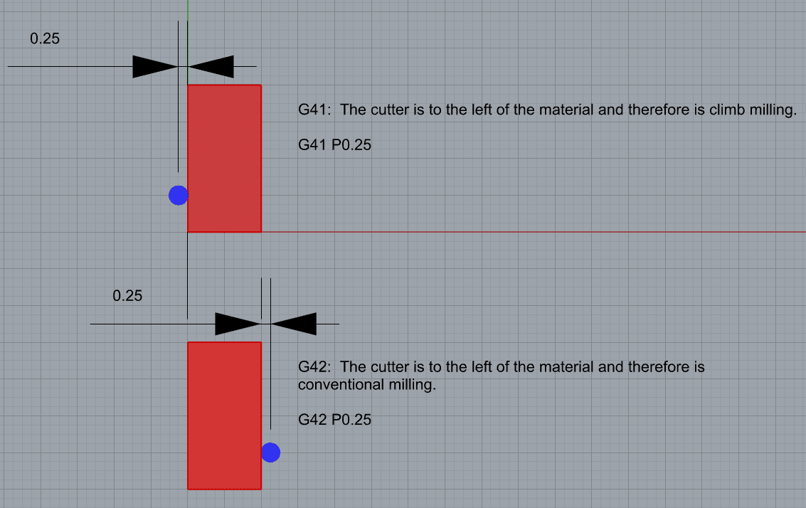
What is the difference between G41 and G42 G code?
The difference is G41 performs left cutter compensation and G42 performs right cutter compensation. See this diagram for more:
Conclusion
Gcode g41 and g42 provide CNC machinists with invaluable tools for achieving accurate cuts and intricate machining operations. These tool compensation codes, including G40 for tool nose radius compensation, enable operators to produce complex geometries, maintain consistent part dimensions, and optimize surface finishes.
When combined with programming techniques that involve multiple codes (G41/G42) and additional parameters (D, H, I, J, K), the possibilities for CNC machining expand exponentially. By mastering these advanced applications and variations of cutter compensation codes, machinists can unlock their full potential and embrace the intricacies of modern manufacturing.
With a deep understanding of these codes' functionalities and thoughtful programming practices, machinists can elevate their craftsmanship to new heights. So let us embrace the power of gcode g41 and g42 with confidence and creativity as we shape the future of CNC machining one code at a time.
Be the first to know about updates at CNC Cookbook
Join our newsletter to get updates on what's next at CNC Cookbook.