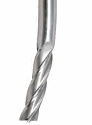
Remember: This is the 4th tutorial in the Free Email Feeds & Speeds Master Class. Click here for more information about the Master Class.
Well, if you're not afraid of tool deflection, you should be.
But how much is too much deflection, and how should we think about it?
Tool Deflection has four evils:
- It can instigate chatter. If deflection is low enough, chatter in machining is much less likely.
- It can reduce tool life. Deflecting a tool is bending the tool, and we all know what happens when we bend a paperclip too many times!
- It can ruin surface finish. Depending on the conditions, the tool may deflect into the wall of the cut leaving a chatter-like ripple.
- It messes with tolerances. Your CAM software assumes a perfect cylinder, not a deflected bent up one that is thrashing around in the cut.
OK, then what are the limits of Tool Deflection? Why? And is G-Wizard Calculator optimistic or conservative about those limits?
I recently finished several fairly in-depth discussions with folks running expensive production machining jobs about the limits of Tool Deflection and how to think about them. First, Tool Deflection is extremely important to Tool Life, Chatter, Surface Finish, and the Tolerances on your jobs. If your Feeds and Speeds ritual does not involve checking the Tool Deflection, you’re leaving money on the table and likely dealing with problems you’d rather not deal with.
If you prefer video, I did a video for Cutting Tool Engineering magazine that was totally focused on Tool Deflection. In it, you’ll learn:
- What tool deflection is
- How it hurts tool life
- How much you can get away with
- All the strategies for getting rid of it
Check it out:
Let's dig in and understand the topic more deeply.
How G-Wizard Sets Deflection Limits to Avoid Chatter
Let’s start with how G-Wizard determines deflection limits. They’re very conservative and are based on recommendations from major tool manufacturers like Ingersoll designed to limit the onset of chatter. These are in fact the most conservative limitations on deflection. And it's important to avoid chatter because it will tear up your tools faster than almost anything.
For roughing, a limit of 0.001″ is set for a typical solid endmill of 1/2″ or so, and this is scaled based on cutter diameter when you start talking really small endmills or really big ones. Since this is the most conservative limit on deflection, we can be assured that Tool Life, Surface Finish, and Tolerances are likely taken care of too with this limit.
If you wonder about chatter and deflection, pop over and watch the great Haas video where they vary spindle speed to control chatter on a lathe. The reason they have the chatter is they’re hanging bars out too far without a tail stock and they’re deflecting. This time it’s the workpiece and not the tool, but the principle is the same.
When finishing, we will want a tighter limit, primarily for surface finish and tolerances. We rely on the finish pass to clean up tolerance issues that may have developed due to deflection, and in fact, tolerance is the most generous allowance for deflection, so we can mostly ignore it given a finish pass for clean up. After all, if we’re going to shave 15 thou for the finish pass, we can tolerate up to 15 thou in the roughing pass. Our deflection should be much less than that under any circumstances. G-Wizard will automatically tighten the limit in Cut Optimizer for Finishing.
What if There’s No Chatter?
Can you exceed G-Wizard’s chatter-based Deflection warnings? Absolutely–chatter may not have been a risk for the combination of parameters you were using for the cut. But you need to think about what your strategy for chatter is going to be. For many, avoiding even the possibility of chatter is better than dealing with it in the heat of a job. If that’s the case, respect the limits G-Wizard sets.
OTOH, if you’re going for broke on your Material Removal Rates or you are having to deal with deep pockets that won't accommodate large enough tools, you need to consider more aggressive strategies. You could just forge ahead and choose to deal with chatter if it comes up. That being the case, you can probably tolerate a higher deflection limit. G-Wizard provides a means to change that limit on the Setup Other tab:

You can override G-Wizard’s Deflection Limit on the Setup Other tab…
Here's what the options do:
- Limit Chatter: Chooses a very conservative deflection limit that helps avoid chatter. This is the default.
- Best Finish: Chooses a much lower limit if you are in the Finish (non-Roughing) portion of the Tortoise-Hare slider. This helps reduce tooling marks in the wall of the cut for better surface finish. This is OFF by default.
- Deflection Limit: If you turn off "Limit Chatter", this area is enabled. It lets you set a Deflection Limit that is a percentage of maximum chipload. It also tells you the impact on Tool Life. For example, at 20% of max chipload, Tool Life is 92% of normal.
If you're in a tough situation and need a higher deflection limit, turn of Limit Chatter and dial up the Deflection Limit until you hit a Tool Life value that is as low as you can stand.
If your shop is fortunate enough to be taking a scientific approach to chatter, you can probably quit worrying about chatter when choosing your deflection limits. Chatter is highly repeatable and largely depends on just four variables:
- Machine
- Tool Holder (not the exact holder, just the same brand and model)
- Tool (again, just the same brand and model)
- Stickout
That’s a manageable number of variables, and if you know the chatter danger zone in terms of spindle rpm for those variables most of the time, you’ll know whether chatter is even an issue for the Feeds and Speeds you’re contemplating.
Deflection and Tool Life
Moving along from Chatter, the next issue for Deflection is Tool Life. Here, Tool Deflection acts like Tool Runout. In fact, they are additive. Think of your Tool Life as being subject to Runout + Deflection. Now given that combined number, and for a good spindle, you might assume runout is nil and view it totally as a function of Deflection, let’s look at the impact on Tool Life (taken from our article on Tool Life vs Runout):
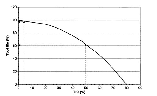
Tool Life as a function of Runout, where Runout is measured as a % of chip load…
The chart measures Runout (or Deflection as we’re talking about here) as a % of chip load, which makes sense. Bigger cutters allow more chip load and more runout.
Let’s say we’re running a 3/4″ endmill for a roughing operation. G-Wizard’s default on a TiAlN Carbide Endmill suggests a max of 0.0036″ chip load. You can buy endmills that allow more, but let’s run with this. If we take G-Wizard’s 0.001″ deflection limit, that’s about 28%. We can see from the chart we’re still going to get 90% of our Tool Life or so. Deflection is probably not the big factor.
But, what if we run 0.003″ of Deflection–3 times G-Wizard’s recommended limit. Now we’re at 83% of chip load and the chart suggests we’re probably going to break that tool in short order. I look at that chart and about 80% Tool Life, which corresponds to 35% of chip load for the Deflection, seems like what I’d be willing to put up with to get a little more aggressive cuts.
That tells me I might set G-Wizard’s Deflection Limit (on Setup Other) up to maybe 120-125% if I wanted to live life on the aggressive side. As it turns out, G-Wizard’s default is pretty reasonable for most users.
Another thing to consider-the lower your cutter's chipload, the lower its tolerance for deflection. To be more concrete, very small cutters are super sensitive to deflection because they can't tolerate much chipload. In fact, excessive runout is the #1 killer of micromilling cutters, so it stands to reason deflection is probably right up there too.
Other Odd Tool Deflection Pitfalls
Sometimes, there will be other considerations for Tool Deflection. I was visiting a shop one day that had just gotten Volumill in for HSM toolpaths. They wanted to try it out and fired off a job. Things were going nicely when suddenly we heard that telltale “PING” as the cutter bounced off the enclosure window. Dang, broke a cutter. What happened?
He hadn’t used G-Wizard for Feeds and Speeds, so I immediately checked it out. The only thing amiss was an excess of Tool Deflection. Upon examining the part closely, here is what we saw:
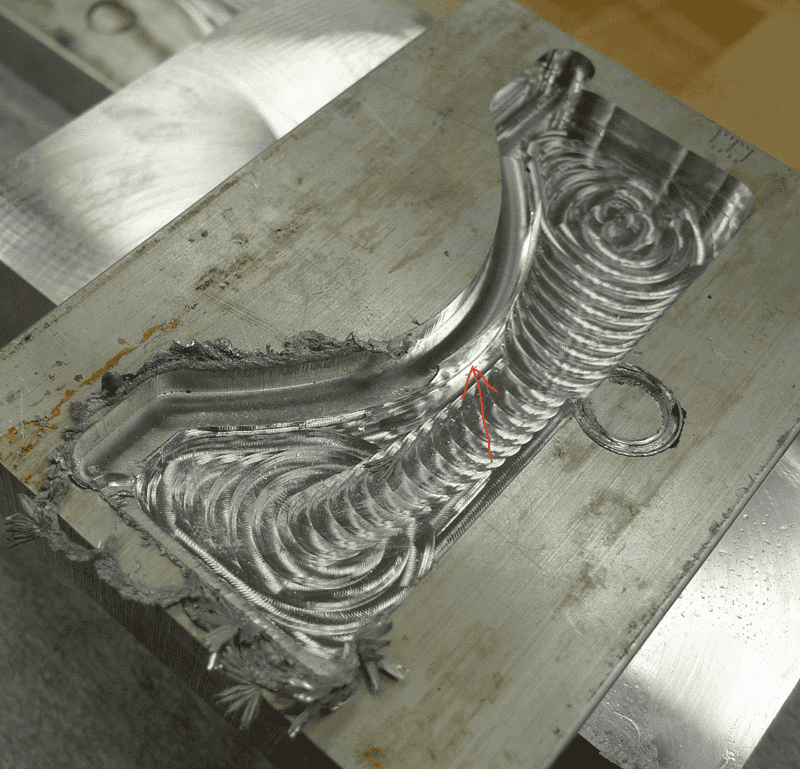
See the tiny wall the red arrow points too?
See the tiny wall the red arrow points to? Because of tool deflection, the cutter wasn’t where it was expected and we got that little wall. It shrouded the cutter from coolant reaching it for a very short time before the cutter broke.
Problems like this are almost unpredictable, but they can crop up if we’re too aggressive all the time with Tool Deflection.
Using a Chipload Budget to Manage Deflection on Tough Jobs
More recently, I had a conversation with another customer about why a cut was working. It seemed like it had an awful lot of deflection. But it turned out something very interesting was happening. This was one of those tough jobs that required a lot of stick out to get down into a hard to reach place. They were running very little Cut Width and as a result, there was Radial Chip Thinning, which meant chip loads were artificially low.
It turned out that the sum of the Tool Deflection and the actual chip load were well within the limits of max chip load for the endmill. In effect, we had a “Chipload Budget” where part was allocated to the actual chip and part was allocated to the Deflection. It was working out just fine for them.
This trick is worth keeping in mind for those difficult jobs. Sometimes you may need to trade some excess Deflection for some reduced chip load to get those jobs done without taking too many passes. Doing so enabled this particular job to be done in one full flute length pass. Very clever!
Another tip:
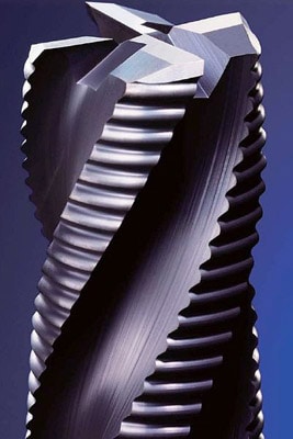
Use a Serrated Roughing End Mill for high deflection jobs.
All else being equal, they generate less cutting pressure than a standard end mill, and hence, less deflection.
Tool Deflection is bad for Surface Finish
Now that you understand the impact of Tool Deflection on Tool Life, let's look at its impact on Surface Finish. It should be pretty obvious that tool deflection is bad for finish, but I got a great look at it one day while watching one of John Grimsmo’s knifemaking videos.
Tool deflection eventually broke the endmill, and John’s video captured it perfectly at about 9:22.
But you can also see that instead of getting a smooth wall, you get a wavy one as the tool deflects rhythmically in time with revolutions and flutes. Here is what such a wall looks like in this shot from John's video:
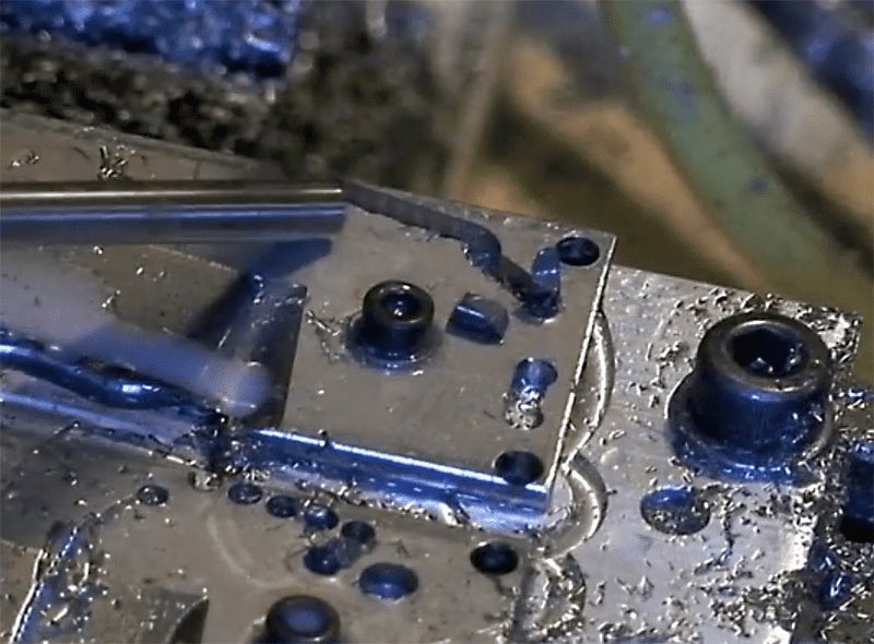
The wavy wall on this cut is due to tool deflection...
Tool Deflection is bad for Accuracy
This will be the last of the "4 Tool Deflection Evils." Accuracy has to suffer when the tool tip is flapping around due to vibration. In practice, a little bit of this can be tolerated, although depending on your stepover, you'll need to beware problems like the coolant wall described above.
A little thought tells us we want to have little or no deflection when the time comes to do the finish pass and accuracy counts. Think about what you expect from your measuring tools.
How to Fix Tool Deflection Problems
Stickout, Diameter, and Tool Material (Rigidity) Resist Deflection
Let's start to get a handle on the root causes of deflection so we can get control over deflection. A big part of it is tool rigidity, which is mostly determined by stickout (distance from toolholder to tip of tool), tool diameter, and tool material. G-Wizard Calculator has a Rigidity Calculator that can help us to wrap our heads around rigidity. We're going to use it to explore what happens as we change these three variables:
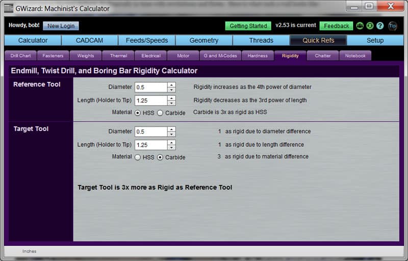
Carbide is 3x more Rigid than HSS...
First, you can see the Rigidity Calculator is located under "Quick Refs" and "Rigidity". We've chosen a 1/2" endmill with 1 1/2" of stickout. The only difference between the two choices is the lower one is made of carbide and the upper is HSS. The Calculator tells us that this change alone is worth a 3X increase in rigidity. That's a big win and is one more advantage of carbide. Should you then always use carbide? Many do, but here is something that's not as well known-if you must live with a certain amount of deflection, HSS will withstand more than carbide. HSS is more flexible while carbide is more brittle. This is sometimes helpful to know when all else fails.
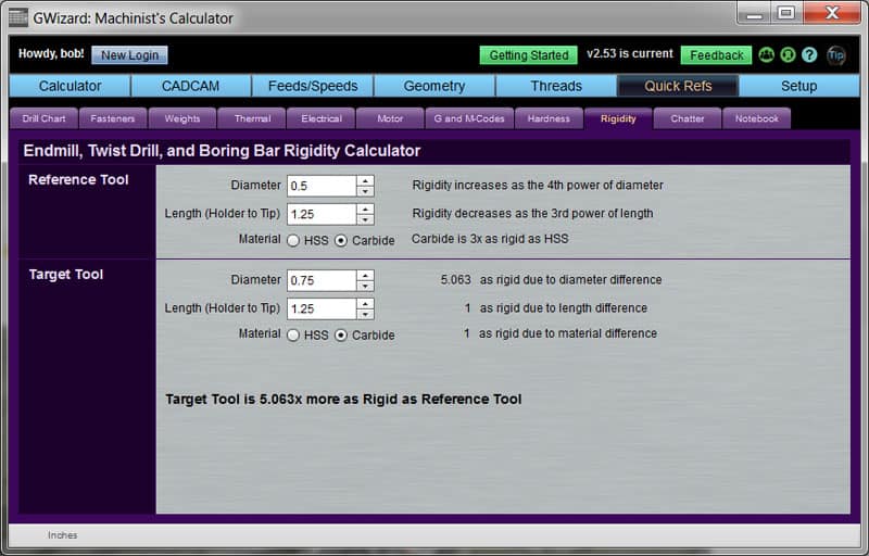
Increasing diameter from 1/2" to 3/4" is worth over 5x the rigidity!
This example shows what happens when we increase tool diameter. Going from a 1/2" to 3/4" endmill, a 50% increase in diameter, netted over 5X more rigidity. That's a big win. The goes to the topic of "Design For Manufacturing," which is all about changing the design to make it cheaper to manufacture.
Designers are only human, so they will often specify a corner radius as a nice round number. Say, 1/2". Of course endmill manufacturers are human too and offer the endmills in standard sizes. What you want is use an endmill just slightly smaller than the corner radius because that's going to make the nicest cut and be easiest on the endmill, but you want that endmill to be as large as possible while still being smaller than the radius, because the minimizes the deflection, lets us take a beefier cut, and so on.
The best way to handle this is for the designer to make the corner radius a little larger than standard endmill sizes. But, there is also a sneaky back door approach. Get out your endmill catalogs. You could try a 7/16" and see if you like that better than a 1/2" endmill for a 1/2" corner, or you could take a look at the metric sizes. You can get either a 12mm or a 12.5mm, both of fall between the 7/16" and 1/2" Imperial sizes. Go ahead, sneaky is good in this case!
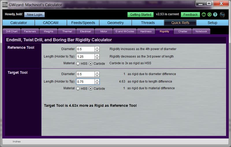
Reducing stickout from 1.25" to 0.75" buys us 4.63x more rigidity...
The last variable we'll play with is stickout. Reducing the stickout from 1.25" to 0.75" (back on a 1/2" endmill again) buys us 4.63x more rigidity. Never use more stickout than you need to.
The Rigidity Calculator further tells us how much each variable impacts things and lists them from most impactful (Diameter) to least (Material):
- Rigidity increases as the 4th power of diameter. Little changes in diameter can make HUGE changes in rigidity. Remember that sneaky metric diameter trick for those super deep pockets where you can't reduce stickout.
- Rigidity increases as the 3rd power of length (stickout). You can still make a big difference by reducing stickout a little bit.
- Switching from HSS to Carbide gives a flat 3X improvement.
Flute Tricks to Reduce Deflection
All things considered, more flutes can mean more rigid endmills and therefore less deflection. The reason is that with fewer flutes, there is usually a larger solid core diameter.
You might consider using a 3 flute instead of a 1 or 2 flute endmill in aluminum to pick up more rigidity.
Also, pay close attention to flute length. The openings in each flute mean less core material to resist deflection. So, the longer the flutes (vs solid shaft), the less rigid the tool. So, use cutters whose length of cut is long enough for your deepest pass (but just the portion that's cutting) and no more. You don't want flutes sticking up out of the cut because you get no rigidity value from them.
BTW, G-Wizard properly accounts for flute length and number of flutes when it calculates deflection-natch!
Effects of Climb vs Conventional Milling on Tool Deflection
Most CNC machinists use Climb Milling for everything and never try Conventional Milling. There are very sound reasons to consider Conventional Milling that are covered in an article in the Feeds and Speeds Cookbook. Take a look at that if you haven't already, but we're going to take a little mini-excerpt from it to consider the effect on Tool Deflection. Basically, what changes is the direction the tool tends to deflect:
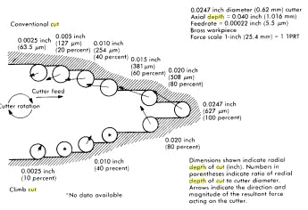
The arrows show direction of deflection, climb is at bottom, conventional is at top...
Note that its really hard to predict these directions by calculation, these were actually measured from real cass. The cutter is feeding to the right, so lets see how that compares to the arrows. Note that the examples to the right show progressively deeper cut widths.
What we can see is that in conventional milling, with lighter cut widths, deflection makes the cutter "pull back" from the cut a bit. That's a nice safety feature because it reduces chip load. But, if we bury it, the arrow shifts to force the cutter to not only pull back, but also a bit into the wall. This starts out as a wash, but eventually it results in increased chip loads. By contrast, lighter climb milling forces the cutter to deflect forward into the cut and a bit inward away from the wall.
In general, imagine that Conventional Milling deflects out of the cut and Climb Milling deflects into the cut. You'd prefer deflection along the direction of travel because that reduces waviness in the wall and if possible for the direction to be not only along the travel but pulling back from the cut. That's a really long-winded way to explain what some of the more experienced machinists have discovered by trial and error. Quoting from the Cookbook article (link above):
You should switch to conventional milling for the finish pass if you're at all deflection challenged (use G-Wizard to see if your tool diameter and stickout result in small enough deflection for your finish pass). At the very least, one should avoid too much depth of cut when climb milling lest it invite deflection. The same article suggests that when deflection is to be minimized, use no more than 30% of the diameter of the cutter for conventional milling and 5% for climb milling. Of course here again, if you have G-Wizard, you'll know what kind of deflection to expect and whether it's a worry.
Climbing to rough and conventional to finish is inline with the consensus over at Practical Machinist as well.
Properly managing deflection can help you avoid the need for an extra spring cut, which saves time and money.
G-Wizard Calculator can help you control Tool Deflection
If it isn't obvious by now, Tool Deflection is important and you could use some help managing it. We've built a number of facilities into G-Wizard Calculator to help with Tool Deflection. You've seen the Rigidity Calculator above. GW Calculator's Feeds and Speeds Calculator will show you the deflection for any cut:
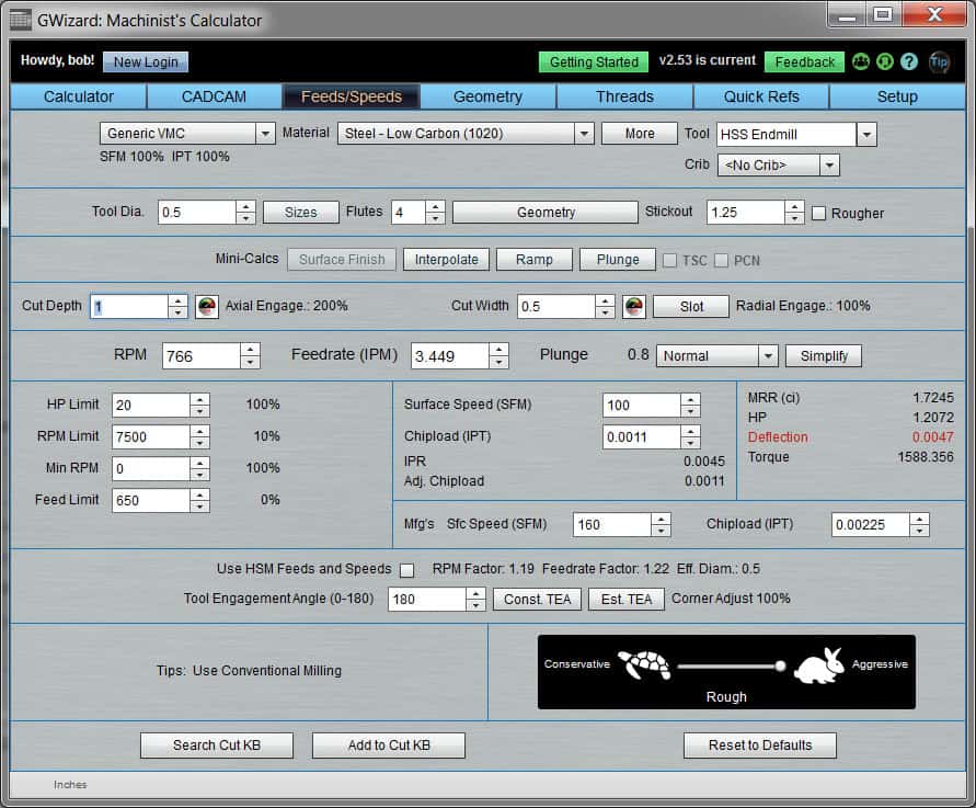
Check the red: almost 5 thousandths of deflection on this cut...
We're trying to cut a slot 1" deep with a 1/2" HSS endmill. Because the slot is so deep, we can't reduce stickout which is stuck at 1.25". What do we do?
Well, as we learned, we could switch to carbide:
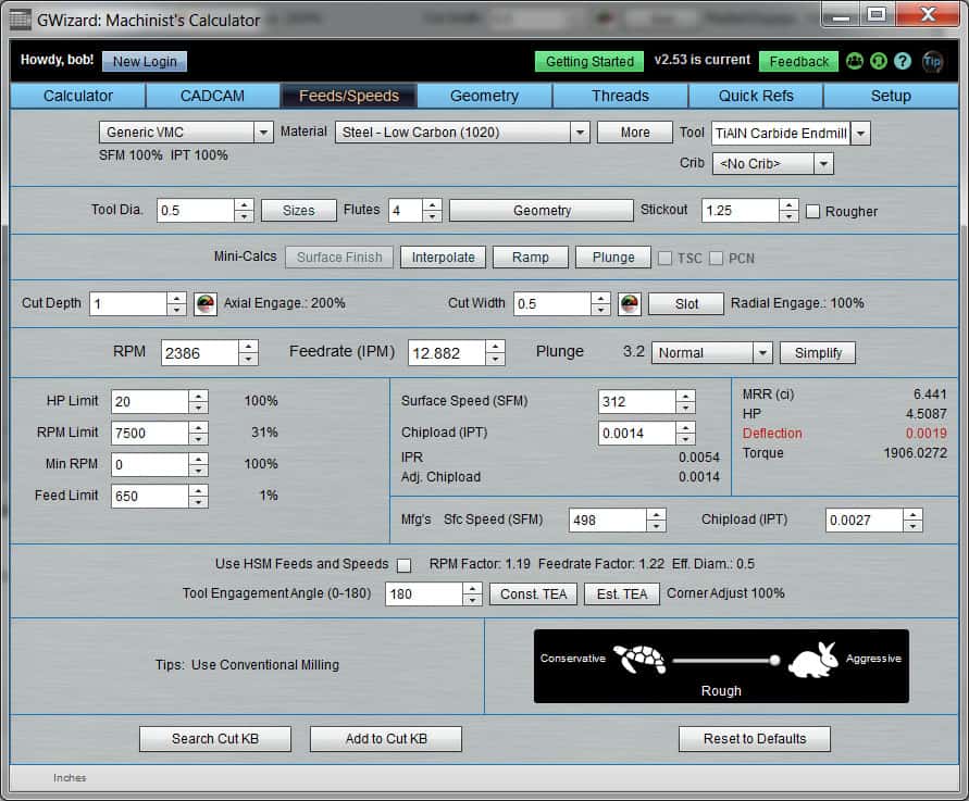
Switching to carbide helps a lot but isn't enough...
Switching to carbide helped a lot, but it's not enough. Let's say a larger diameter cutter is just not an option. Rather, what we need to do is figure out the Cut Depth that keeps deflection under control. That's what G-Wizard's Cut Optimizer is designed to do. Just click the little speedometer next to Cut Depth (since that's what we want to calculate-there's another little speedo next to cut width if you prefer to change that) and it'll pop up with the answer:
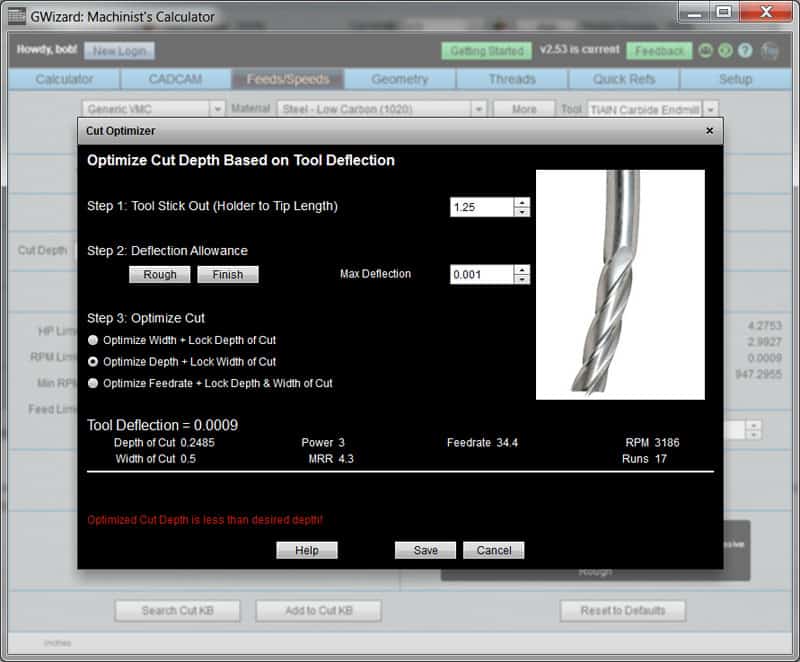
With one click, Cut Optimizer determines the best depth of cut would be 0.2485"
With one mouse click, Cut Optimizer determines the best depth of cut would be 0.2485", and you can save that back to Feeds and Speeds. Done!
GW Calculator also has a feature called CADCAM Wizard that will suggest the optimum tool, stickout, hints for designers (based on that Design for Manufacturing stuff), cut depth, cut width, and feeds and speeds all while controlling tool deflection. There is no more complete solution for Tool Deflection problems available anywhere.
If you haven't played with G-Wizard Calculator yet, try a free trial. You'll be surprised at what all it can do for you.
Tool Deflection FAQ
What problems can excessive Tool Deflection cause?
Excessive tool deflection can reduce tool life, increase the likelihood of chatter (further reducing tool life), destroy surface finish, and introduce dimensional inaccuracies to the part.
How much Tool Deflection is allowable?
Think of tool deflection as being additive to runout. We all know that excessive runout can severely impact tool life. If runout + tool deflection is 50% of the recommended chipload for your cutter, the tool life is decreased to just 60% of normal tool life. When you consider that the chipload of a 1/2" 4 flute carbide endmill in steel should be about 0.002", then a thousandth of an inch of excess deflection will reduce your tool life to 60%! Smaller end mills can tolerate much less deflection. In addition to this direct wear, tool deflection can induce chatter, which will also severely reduce tool life. Most machinists don't realize just how sensitive tool life is to tool deflection.
What is the effect of tool diameter on Tool Deflection?
Doubling the tool's diameter makes it 16x more rigid, and therefore deflection is 1/16th as much, all other things being equal.
What is the effect of tool stickout on Tool Deflection?
Stickout is the distance from tool tip to the bottom of the tool holder that supports the tool. Always use the minimum stickout that provides enough clearance for the job. Halving the tool's stickout makes it 8x more rigid, and therefore deflection is 1/8th as much, all other things being equal.
{"@context": "https://schema.org","@type": "FAQPage","mainEntity": [ {"@type": "Question","name": "What’s The Difference Between Ferrous and Non-Ferrous Types of Metals?","acceptedAnswer": {"@type": "Answer","text": "The simple answer is that Ferrous Metals contain Iron while non-ferrous metals do not. Steel and its many alloys are the most common types of ferrous metals being machined today." }}, {"@type": "Question","name": "What are the 4 types of Steel?","acceptedAnswer": {"@type": "Answer","text": "There are 4 types of steel: Carbon Steel: Steel that has low, medium, or high concentrations of carbon. Alloy Steel: Steel that has had substances added to improve its mechanical properties. Stainless Steel: Steel that is specially formulated to resist corrosion or high temperatures. Tool Steel: Steel that is specially formulated with the properties needed for tool making, such as high hardness." }}, {"@type": "Question","name": "How much carbon is in carbon steel?","acceptedAnswer": {"@type": "Answer","text": "Low carbon steel (mild steel) contains 0.04% to 0.3% carbon. Medium carbon steel has 0.31% to 0.6% carbon, making it stronger than low carbon, but also more difficult to form, weld and cut. High carbon steel has between 0.61% and 1.5% carbon. It is very difficult to cut, bend, or weld." }}, {"@type": "Question","name": "What is the strongest grade of steel?","acceptedAnswer": {"@type": "Answer","text": "Type 440 steel, which is a higher grade of cutlery steel. It can be hardened to Rockwell 58 hardness, making it one of the hardest stainless steels." }}]}
