What is Spindle Runout [Definition and Meaning]?
Spindle Runout, or Tool Runout, as it can also be called, is the inaccuracies that cause a tool (in a mill) or workpiece (in a lathe) to spin off the ideal axis. It's very bad for tool life, so it's good to know more about it.
Runout is the tendency to spin the tool around a centerpoint that is not the tool’s center. It makes the tool wobble instead of spinning cleanly and increases chip loads.
It’s a particular source of tool breakage for smaller cutters because runout is additive to chip load. In other words, if you have a toolholder with 0.003″ of runout (that’s terrible, by the way!), and your endmill is only rated for 0.004″ of chip load, then you can only program a cut with 0.001″ of chip load (0.004 – 0.003) or you’ll exceed the cutter’s chip load limits.
Aside from such catastrophic failures, runout is bad for tool wear in general.
We can create a run out definition very precisely using GD&T for specific situations.
GD&T (Geometric Dimensioning and Tolerancing) is the science of defining and tolerancing allowable errors in manufacturing. Runout is so important to the design of rotating machinery that GD&T even has two kinds of runout:
- Circular Runout: Which measures runout only at certain specified circular cross-sections.
- Total Runout: Which measures runout along an entire cylinder.
For the working machinist, it is perhaps more important to define run out as simply a measurement of the spindle runout of a tool (or workpiece) installed in the CNC Machine's spindle directly.
How to Measure Spindle Runout
Given a dial test indicator and a magnetic holder, it's not hard to measure spindle runout for a tool in the spindle:
There appears to be no text provided for rephrasing. Please add the needed text for me to process the request.
Photo and description of measurement courtesy of PreciseBits.com
The measurement shown will get you runout from all sources, but it's important to understand that you may want to measure the individual component sources of spindle-tool runout to find the underlying causes.
This requires several measurements:
1. Clock the inside of the spindle taper to see the spindle’s runout.
2. Clock a precision dowel in the toolholder to see the toolholder’s runout.
3. Clock the taper inside an ER collet chuck with no collet installed to see the runout of just the toolholder rather than the toolholder + collet combination.
There's even a fourth source that's very hard to measure which is that the endmill may have been ground with its geometry slightly off-center.
Here are a couple videos showing how it works:
Measuring runout on several kinds of toolholder on a VMC…
This video gives a good idea how to measure the runout and also does a good job showing the relative runout of 3 jaw drill chuck, ER collet chuck, and set screw type (Weldon shank) holders. You can surely see that while drill chucks may be fast and easy, they have a lot of runout. Set screw holders also have considerable runout compared to ER collet chucks which have little or none.
For comparison, here’s a guy running a bunch of TTS ER Collet chucks through the test to see what kind of runout he gets:
Testing TTS ER Collet Chucks on a Tormach mill…
There’s a bit more runout than on the VMC, but it’s not too bad.
Runout vs Tool Life
We've all heard that runout is very bad for tool life, but just how bad is it?
Big Kaiser ran tests with drills and reducing runout on carbide drills from 0.0006" to 0.00008" (tiny!) resulted in a 3x tool life improvement. Wow!
There are a lot of rule of thumb and anecdotal answers floating around the web, but here's a quick and easy to understand chart that explains how runout affects your tool life:

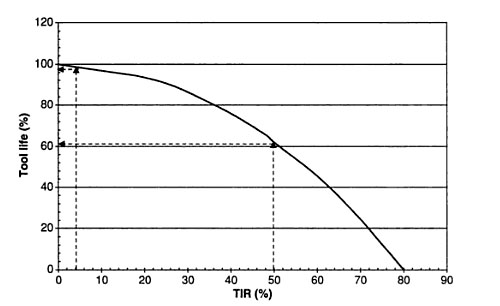
Runout (TIR) as a percentage of chip load versus Tool Life...
In this chart, runout is given as a percentage of chip load, which is the thickness of a single chip being sliced off by your cutter. This is how I like to think of runout-it increases chip load beyond what you intended. As you can see, tool life goes down dramatically when we get to TIR's (Total Indicated Runout) beyond about 20% of your cutter's targeted chip load. This also explains why runout is so hard on tiny cutters-they have small chip loads and can tolerate very little runout as a result.
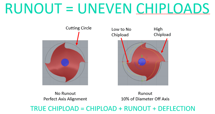
To understand visually how tool life is impacted by spindle runout, I put together this diagram:

As you can see, runout creates uneven chip loads, so some flutes get way too much and wear fast while others get too little. That's not a happy situation for your endmills!
Let's work through a couple of examples. Let's say we've got a 1/2" endmill in a Side Lock (Weldon Shank) Toolholder. Further, let's suppose the spindle has maybe 0.0003" of runout, so it's not real tight, and our Toolholder adds another 0.0005" since its set screws will tend to push the tool off center. That means we've got 0.0008" of runout. So, if we want that to be less than 20% of chip load, chip load must be greater than 0.0008/0.2 = 0.004. How realistic is that?
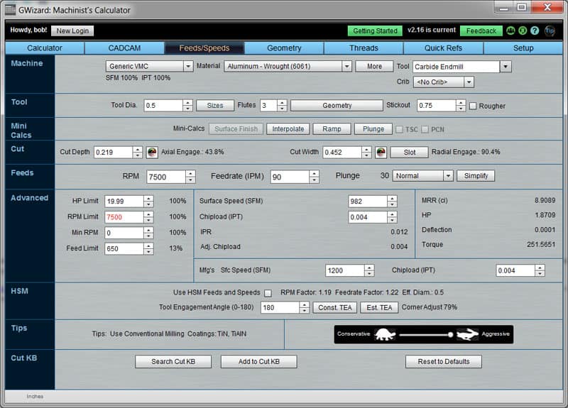
If we set up an aluminum cutting scenario in G-Wizard Calculator, it might look like this (the Cut Width and Cut Depth were optimized by CADCAM Wizard):

Roughing scenario for our 1/2" endmill...
This scenario wants a chip load of 0.004, so we are right at that limit. We'd be better off with an ER Collet Chuck (less runout) to give a safety margin, but we'll probably live to tell the tale.
Now let's try the same setup with a 3/8" endmill. Changing endmill size won't make our spindle have any less runout and it probably won't affect the Side Lock holder much either so our max chip load must be greater than 0.004 again. G-Wizard suggests we need a chip load of 0.0028 in this case, which is less than our limit by a lot. Looking at the Tool Life chart above, 0.0008" of runout against 0.0028 is 29* TIR. Not terrible, but we're definitely going to reduce tool life to 80 odd percent of normal. We would definitely prefer an ER Collet Chuck at this endmill diameter.
Where it gets really crazy is small endmills. Running the same kinds of numbers against a 1/8" endmill suggests we run 0.0006" of chip load. Now we have over 100% TIR since 0.0008" is larger than our allowable chip load. That endmill will definitely be broken very quickly in that scenario.
As a matter of fact, runout is usually the #1 factor affecting tool life for micromachining. I made a video that's all about in my monthly “CNC Chef” series for Cutting Tool Engineering Magazine:
In this video I talk about runout in depth and it’s impact on tool life when micromachining.
Now you can understand why there is so much harping about runout versus tool life!
How to Improve Runout to Improve Tool Life
It's important to be aware that runout can kill tool life. But Runout doesn't have to be something you simply accept. There are ways to improve runout in order to improve your tool life.
Keep It Clean!
Obviously if there's a chip stuck in your spindle taper or in the toolholder, it can cock the assembly and create runout. Always clean and inspect your tooling and spindle taper to make sure this won't be a problem.
Minimize Stickout
Runout need not be perfectly parallel to the spindle axis. Perhaps the tool is also cocked at an angle. That means the longer the tool tip sticks out of the holder, the worse its runout will be at the tip. Always minimize tool stickout to create maximum rigidity and minimize runout.
Use better tool holders
Higher quality toolholders have less runout, or at least they should. Sometimes toolholder type creates runout too. Set screw holders and Jacobs Chucks typically have more runout than ER Collets, for example. It may not be much more, but it adds up as we've seen.
My micromachining video above talks about even higher quality systems that are needed for to reduce runouts to the tiny amounts that are tolerable when micromachining.
Check Runout and Replace Tooling as Needed
I drag out my dial test indicator if I'm having unexplainable problems with tool life just to make sure.
I was in the shop one day and managed to break 5 eighth inch endmills in a row before I finally decided to start checking runouts. I traced it to a brand new ER collet that was bad out of the box.
BTW, ER collets are consumables and must be replaced periodically.
"Clock" Your Toolholders
Runout is a tolerance that stacks up. There is spindle runout, toolholder runout, perhaps collet runout in the toolholder, and so on.
Given that runout occurs when geometry is offset from the true axis of rotation, we can reducing runout by "clocking" runouts of the components so they cancel each other out.
Suppose you know the direction of maximum runout for your spindle (you can measure it!). Put a mark with a Sharpie and rotate the spindle so it is at 3 o'clock.
Now measure runout on a toolholder (perhaps using V-Blocks on a surface plate) and mark the maximum runout position with a Sharpie.
Now, when you insert the toolholder in your spindle, put the toolholder mark at 9 o'clock. It's 180 degrees from the spindle's 3 o'clock runout.
Voila! The two are at least partially cancelling each other out and the tool enjoys reduced runout.
BTW, here's an interesting bit of information.
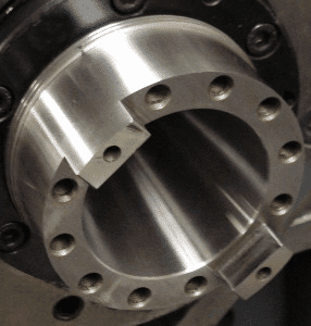
Every CNC machinist has seen the ubiquitous “drive dogs” found on many tapers:

Spindle Drive Dogs…
They’re the two little “ears” that engage notches in the toolholder. Not every taper has them, but many do. Getting the drive dogs positioned to line up with the toolholder in the changer carousel before a toolchange can happen is called “spindle orientation” or sometimes “spindle positioning”.
You might think spindle orientation is only about lining up the drive dogs with toolholder notches, but I recently learned differently. There are tapers that don't have drive dogs and they still do spindle positioning during toolchanges for a very important reason.
Dave Decaussin, one of the original founders of Fadal, recently remarked on a video I was watching that spindle orientation is also essential to maintaining tolerances while machining.
The reason is (drumroll please) runout. Exactly what we're here to talk about!
When you maintain the same spindle position relationship to the toolholder, you ensure that whatever runout there is will at least be consistent–either consistently good or consistently bad. Consistency is the main thing, because if it is consistent, we can compensate for it.
If you think about it, the runout just makes the endmill act like it is a slightly larger diameter as it wobbles in the cut. If that effective diameter changes every toolchange, the CNC machinist will have a tough time maintaining tolerance. But if it is consistent, there is hope. You can use your wear offsets to just enter the effective diameter of the tool and cut accurately despite that runout.
It’s good to learn at least one new thing every day!
Retention Knobs (Pull Studs)
Retention Knobs are a consumable that sits atop the toolholder. The machine's powered drawbar engages the retention knob to pull the tool holder up and seat it in the taper. But, if the knobs get worn or aren't made to good tolerance to start with, they can be a source of added runout.
Spindle Condition
Worsening spindle runout over time is an indication of wear problems on your spindle. It's always a good idea to keep a log of such things so you can track the trends. If runout gets bad enough, it may be time to rebuild your spindle.
Conclusion
Runout can dramatically reduce tool life, but now you know how to measure it, and you have some tips on how to reduce it.
Be the first to know about updates at CNC Cookbook
Join our newsletter to get updates on what's next at CNC Cookbook.