Hello CNC'ers! Today, we'll discuss tool wear and how you can diagnose it for a job. In general tool wear is loss of material from a cutting tool. Wear entails a loss in the volume and geometry of the tooling. Wear of tools is caused by several factors.
Excessive tool wear will show unwanted effects on your workpiece, so it is important to avoid tool wear in order to achieve optimal results. Tool wear can also lead to tool failure, which in turn can lead to serious damage, rework, and scrapped parts.
Both thermal and mechanical stresses cause tool wear, with heat and abrasion being the major causes.
Types of Tool Wear
Tool wear common to cutting tools can be categorized in the following types:
- Abrasive Wear
- Edge Chipping
- Flank Wear
- Crater Wear
- Thermal Cracking
- Built-Up Edge
- Notch Wear
- Plastic Deformation
Let's go through and see what each type of wear is and what causes it.
Abrasive Wear
Abrasive Wear is the normal mechanical abrasion caused by the workpiece on the tool.
This wear dulls the cutting edge of a tool. Eventually, it can even alter dimensions such as the tool diameter. At higher speeds, excessive heat becomes more of an issue, causing more damage to the cutting edge. Using an appropriate tool coating can reduce this problem.
If abrasive wear becomes excessive or worse, causes premature tool failure, it may be helpful to reduce the cutting speed and optimizing coolant usage can help.
Even more helpful are High Efficiency Milling (HEM) toolpaths that can help reduce wear by spreading the work done by the tool over its entire length of cut. This prevents localized wear and will prolong tool life by using the entire cutting edge available.
Edge Chipping
This type of tool malfunction occurs when the cutting edge develops chips. These chips lead to poor surface finish, and eventually tool failure.
Cutting Edge Chipping is causes by excessive loads and shock loading while cutting. It can also be caused by thermal cracking. Vibration and chatter can also lead to cutting edge chipping.
Beware of interrupted cuts and repeated part entry can also have a negative impact on cutting tools. Reduce feed rates and/or select a gentler means of entering the cut to reduce the risk of chipping.
Flank Wear
Flank wear can be seen on the side (flank) of the insert. Symptoms are that surface finish gets worse as flank wear increases. In addition, you can visually see and perhaps feel a deterioration of the insert edge by running your nail along the cutting edge.
Flank wear is generally caused by heat and abrasive wear causing the insert to wear down.
If you are experiencing excessive flank wear, consider reducing cutting speed, increasing the feed rate, and picking a more wear-resistant grade of insert.
Crater Wear
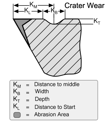
Cratering, or crater wear, is a concave (yes, they look like craters) wear pattern on the rake face of the insert a short distance from the cutting edge.
It is caused by a chemical reaction between the workpiece material and the insert, and it happens as chips flow over the insert’s face at very high temperature. It develops as severe friction between the chip and rake face wears the insert.
This type of wear is most commonly observed where a continuous chip is formed. If left unchecked, this erosion can continue until a breakthrough occurs at the cutting edge.
The elimination of cratering is not always possible, but good results often can be obtained if crater growth is limited so that the maximum allowable flank wear is reached before crater breakthrough occurs.
Crater wear also occurs when the insert is too soft for the heat generated in the cut. Increasing the hardness of the insert will reduce or eliminate cratering. Reducing cutting speed and then the feed will also help reduce this type of wear.
Thermal Cracking
Thermal cracking appears as cracks that are perpendicular to the cutting edge. It is caused by large, rapid temperature changes at the cutting edge. These temperature changes are often referred to as shock cooling. They are most common during interrupted cutting or during the metal cutting of hardened workpieces when cutting fluid is applied intermittently.
Note that it may not be obvious the cutting fluid is only being applied intermittently.
You can partially combat thermal cracking by using a tougher, more wear-resistant grade. However, the problem is likely an incorrect cutting fluid strategy. Applying high-volume, high-pressure coolant—or in situations that will allow, using no coolant—will also help.
Many machinists are surprised when turning off the coolant on their machine tool actually increases cutting tool life.
Built-up Edge
Built-up edge (BUE) occurs when the material you are cutting adheres to, and builds up on, the surface of the cutting tool.
BUE is very common when metal cutting aluminum and stainless steel. These materials marry to like materials in the cutting tool, and BUE only gets worse after it begins. Eventually, it gets so thick that proper cutting action is lost and the cutting tool breaks.
The number one fix for BUE is to make sure you have enough coolant on the cut. You may also need to increase your coolant percentage to add more lubricity to the cut and reduce BUE.
One other common fix for BUE is to raise your surface footage (e.g. increase cutting speed) to add more heat into the cut which lessens the adherence. Take care you don't add so much heat it leads to plastic deformation.
Notch Wear
Tool Notching occurs when the surface hardness of the material is much harder than the hardness of the internal material. It is common when machining stainless steels and nickel-based alloys, in which the surface hardness of the workpiece can be up to 30 Rockwell Hardness C harder than the material underneath, usually due to work hardening.
Increasing your edge prep and varying your depths of cut can reduce notch wear.
Plastic Deformation
Heat softens any material, including your cutting tool. Too much heat can reduce hardness at the cutting point which accelerates dulling of the cutting edge.
The proper application of cutting fluid, a cutting tool material with higher wear resistance, additional coatings, and reducing cutting data can minimize this deformation.
There are some conditions, such as tool rubbing, that generate excess heat, so be sure you're using proper feeds and speeds at all times.
Tool Wear Effects
When a cutting tool has reached its final stages of its life cycle, the tool wear will create wear effects. This impacts the quality of parts produced, equipment's efficiency and downtime arising from operators' actions.
Among the effects of warn tools are:
Poor Surface Finish
The longer the tool wear is the more significant its effect on surfaces. Dull tools can cause uneven or rough cuts in pieces of work. Especially for high-accuracy CNC machines the problem may result in serious quality problems that require rework or scrap.
Increased Cutting Force
As tool wear increases, additional cutting forces are likely. These increased cutting forces can further accelerate tool wear.
Decreased Accuracy of Produced Parts
When parts wear, it decreases their accuracy. All workpieces have tolerance requirements. A single form of tool wear will often be increased when part goes below a specified level and results in the loss of parts. Various forms of wear occur together, cascading deformations reduce the accuracy of the part. Managing tool wear is a critical element in maintaining high quality efficiently.
Tool Life Definition
Tool Life can be defined in several ways including:
- The total volume of material removed with the tool during its life.
- The duration for which the tool is usable for machining, usually expressed in minutes.
- The number of parts the tool can be used to produce.
If a tool breaks, clearly it has reached the end of its life. But most definitions are focused on a more gentle end to the tool. For example, we may define maximum acceptable flank wear, perhaps a value of 0.5mm.
Tool wear is usually not uniform. The wear on a new tool is accelerated, then settles down to a more normal rate, then towards the end the rate of wear goes up again until the tool finally fails catastrophically. Since a catastrophic failure can often mean scrapping the part, this is why we prefer to identify the end of a tool’s useful life before a catastrophic failure.
Tool Life Calculation
In 1907, F.W. Taylor developed an equation that expresses the relationship between tool life and cutting speed (temperature) while keeping feed rate constant.
Taylor’s Tool Life Equation
Taylor’s Equation for Tool Life is:

where
=cutting speed
- T=tool life
- D=depth of cut
- S=feed rate
- x and y are determined experimentally
- n and C are constants found by experimentation or published data; they are properties of tool material, workpiece and feed rate. For example, n is 0.1 to 0.2 for HSS tools, 0.2 to 0.4 for carbide, and 0.4 to 0.6 for ceramic.
One of the main practical takeaways from the equation is that Cutting Speed is a much bigger determinant of tool life than feed rate. All other things considered, increasing cutting speed causes twice as much wear as increasing feed rate by the same percentage.
Depth of cut will also increase wear, but the effect is even less than increasing feed rate. Also, the increased wear of depth of cut is offset by spreading the overall wear over a longer length of cutting edge.That’s the principle behind High Efficiency Machining.
BTW, if you want to evaluate changes in the Material Removal Rate, you will find the Material Remove Rate Formula as well as a lot more about MRR’s in the linked article.
Tool Life Monitoring
Tool Life Monitoring is a collection of technologies used to help automate the process of dealing with Tool Wear. It involves the following:
- Usage Tracking in the Machine’s Tool Table. The total number of minutes a tool has run may be tracked by more modern CNC machines. This number can be accessed via system variables and the g-code can choose to use a different tool or call for the operator to change the tool when total run time reaches a threshold.
- Digital Probes can check wear, breakage, and chipping on the edge of a tool. When the measured diameter changes too much from a given value, the tool can be deemed worn and a replacement called for.
- In some cases, spindle load monitoring can be the early tip off for tool wear since cutting forces increase as the tool wears.
Hard core automation includes tool changers with enough capacity to keep more than one of a given tool size on hand, together with programming to automatically switch to an alternate when wear becomes a problem.
Related Article: Use a Digital Microscope to Monitor Insert and Tool Wear
Be the first to know about updates at CNC Cookbook
Join our newsletter to get updates on what's next at CNC Cookbook.