What is Material Removal Rate (MRR)?

Material Removal Rate, sometimes called Metal Removal Rate, is the rate at which raw material is removed from a part in a given period of time by machining operations. It's abbreviation is MRR.
Material Removal Rate Units
The units for Material Removal Rate are cubic
Why is Material Removal Rate Important?
Material Removal Rate has got to be one of the most important metrics for any shop or machinist to try to optimize. After all, the purpose of almost any machining operation is to remove material, so how fast we can remove material has got to be a critical measurement, right?
For most parts, roughing the part takes longer than finishing it. So raw chip removal power (in the form of higher Material Removal Rates) is going to account for the majority of the time making the part. Like they say, time is money, so when we focus on optimizing Material Removal Rates, we are focusing on making more money.
In many ways, Material Removal Rate is the most important Feeds and Speeds Calculation you can make.
This article will tell you how to optimize your Material Removal Rates for a cutting operation.
Calculating Material Removal Rate

Each machining process calculates MRR with a little different material removal rate formula.
Material Removal Rate Formula for Turning
When turning we calculate MRR as:
Material Removal Rate = Depth of Cut x Cutting Speed (SFM) x Feed Rate (Dist./Rev.).
Material Removal Rate Formula for Milling
When milling we calculate MRR as:
Material Removal Rate = Radial Depth of Cut x Axial Depth of Cut x Feed Rate.
Material Removal Rate Formula for Grinding
When grinding we calculate MRR as:
Material Removal Rate = Depth of Cut x Width of Cut x Feed Rate
[ More Cutting Speed Formulas ]
Material Removal Rate to Calculate How Long a Machining Op Will Take
If we know how much material removed a particular operation must accomplish, we can calculate how long the operation will take using this formula:
Operation Time = Material Removed / Material Removal Rate
Optimizing Efficiency = Optimizing Material Removal Rate
Many shops are not looking broadly enough when they go to Optimize Material Removal Rate. As we will see, there are a number of opportunities to look at ranging from selecting the best tool for higher MRR's all the way to how you go about rough cutting the raw material before it evens goes on the CNC Machine.
Advancements in Astronomy have largely followed steady increases in telescope power, culminating in telescopes in space like the Hubble. Similarly, advancements in physics have tended to follow the race to build bigger and bigger particle accelerators.

It helps to have more powerful instruments, regardless of what science you are probing. And the same applies to feeds and speeds when machining.
As G-Wizard Calculator has become steadily more powerful at manipulating the effects of more and more variables, it has become possible to see behaviors involving complex interactions that were not entirely visible before.
What’s the impact and tradeoffs of axial depth of cut, radial depth of cut, tool diameter, tool deflection, and spindle power curves on material removal rate, for example?
The more variables you can optimize at once, the greater the Material Removal Rate gains you will find.
Our latest step in this vein is the CadCam Wizard. What Cad Cam Wizard is, to simplify matters, is a way to generate optimal feeds and speeds from as little information as possible. This makes it radically simpler for beginners, and the optimization aspect makes it radically more powerful for experts because the Cad Cam Wizard chooses optimal values for more variables so the expert doesn’t have to guess.
One of the inputs it has is something I call the “Roughing Strategy.” Assume we want to cut a pocket. The roughing strategies for pockets are as follows:
- Same: Roughing is performed with the same endmill as will be used for finishing, or at least one of identical material removal characteristics as you might want a newer sharper one for the actual finish pass. For this article, the cutter has a 1/4″ diameter and is assumed to be either a 3 or 4 flute carbide endmill.
- Corncob: Roughing is performed with a serrated “corncob” endmill of the same diameter as the finish endmill.
- Same + HSM: Like “Same” only a constant tool engagement angle HSM toolpath is used for roughing. This will require a CAM program with HSM toolpaths.
- Corncob + HSM: Use a corncob cutter with an HSM toolpath.
- Large: Allow a larger cutter for roughing, so it won’t get into all the corners. This will require either a lot of manual CAM work or a CAM program with Rest Machining capability. For this article, the larger cutter has a 3/4″ diameter and is assumed to be a 3 or 4 flute carbide endmill.
- Large Corncob: Same as large but using a corncob as the larger cutter.
- Large + HSM: Larger cutter with HSM toolpath.
- Indexable: An indexable endmill, 1″ diameter, is used as the roughing cutter.
- Large Corncob + HSM: A larger corncob + HSM is used.
- Indexable + HSM: A larger indexable endmill + HSM is used.
Pretty comprehensive, though I will likely add more over time (plunge roughing, anyone?). I used the Cad Cam Wizard to generate width of cut and depth of that cut for optimal Material Removal Rates (MRR’s), and then I graphed the information to see what effect the different roughing strategies were having.
Here is the graph of the average metal removal rate advantage of each strategy over all materials:
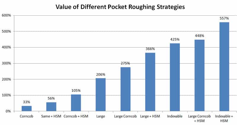
The best strategy was 5.57x faster than just using the same endmill for finishing and roughing, so there’s definitely gold in them thar hills. It takes some combination of tooling and CAM features to unleash the full potential for metal removal rates here, so let’s talk about that first.
BTW, the strategies that involve using larger tools for roughing may also deliver longer tool life, as the bigger tools may be quite a bit more robust.
I will be focusing primarily on milling here, but I will throw in an example or two for other types of machine.
Determining the Ideal Tool for Material Removal Rate
Let's start by choosing what tool we are going to use for roughing.
Where possible, you probably want to use carbide tooling. This is certainly true for end mills, but it may also be true for twist drills. Carbide Drill Speeds and Feeds are higher.
From a simplicity standpoint, and perhaps to save the cost of a toolchange, we might use the same tool as we will be using for finishing. That's probably a mistake though. If we can tolerate the toolchange, we can gain access to much higher Material Removal Rate's.
This happens in several ways. Some tools are purpose made for roughing and can't be used for finished. The serrated or "corn cob" rougher is a great example:
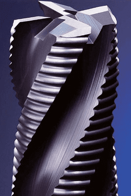
Those serrations break up the chips so they're easier to evacuate. This type of cutter will buzz through roughing cuts faster than regular solid end mills, and therefore they have higher metal removal rates.
What about a larger cutter for roughing than finishing?
I'm so glad you asked!
The finishing cutter has to be able to follow the finished contours of the part. For most parts, this puts an upper limit on the size of cutter. If I am finishing a square pocket whose corners have a radius of 1/8", I can't run a cutter larger than 1/4" to finish that pocket. In fact, depending on how things behave, I may not even be able to use 1/4". It might have to be 3/16" or some such.
But, if I am roughing, I can go bigger. I don't want to make my finish cutter work too hard, but I can probably go 1.5 - 2x larger diameter with the rougher. That means a whole lot higher Material Removal Rate's in all likelihood.
By the way, given that roughing is where the tool works the hardest, you'll benefit from using bigger tools because you're less likely to have a tool failure.
What about indexable tooling?
Another great idea, especially since solid end mills get a lot more expensive to run than indexables as you go up in size. Plus indexable tools can have much better chip clearance so that they can run more cutting edges so their material removal rates are almost scary.
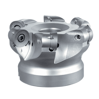
We can go on and on like this and start debating the value of through spindle coolant and a host of other features when roughing. Let's keep it simpler though. There's a Golden Rule you need to know when choosing your rougher.
The Golden Rule for Roughing Tool Selection
So what's the bottom line on tool selection?
- You're probably running different roughing and finishing cutters.
- The rougher should be larger than the finisher and purpose-made for roughing. It may or may not be indexable. If the two are of the same size, a Solid End Mill will outperform an indexable, though at a much greater cost.
Here's your Golden Rule for choosing a Rougher:
Choose the cheapest cutter that will max out your machine's horsepower and still work for the dimensions of the cut and the material.
It really is that simple.
"What about tooling cost?" you ask.
Consider that your tooling is typically about 5-10% of the total cost to machine the part. Most of the costs are hourly in nature. Your operator, the machine, cost of overhead (electricity, rent, etc.) can all be thought of in hourly terms.
If you can halve the time of the roughing by spending twice as much on a cutter, you come out way ahead. That's not an excuse to write an unlimited blank check, but you can spend a lot more on cutters than you'd think and come out ahead.
At the same time, if you are truly maxing out your machine's spindle power, buying even more expensive tooling doesn't make sense unless it is able to extract more workpiece material at the same horsepower limit.
CAM Features for Roughing
This test focused on two different CAM features that matter for roughing: HSM Toolpaths and Rest Machining.
HSM toolpaths allow us to overcome the limitations of plowing into corners where the loads on the tool can double almost instantly. They do this by using special loopy toolpaths that never go into corners except by peeling their way in a little at a time:
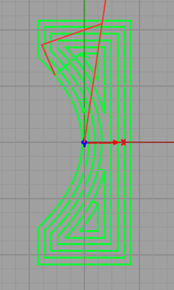
Non-HSM conventional stepover toolpath for pocket roughing…
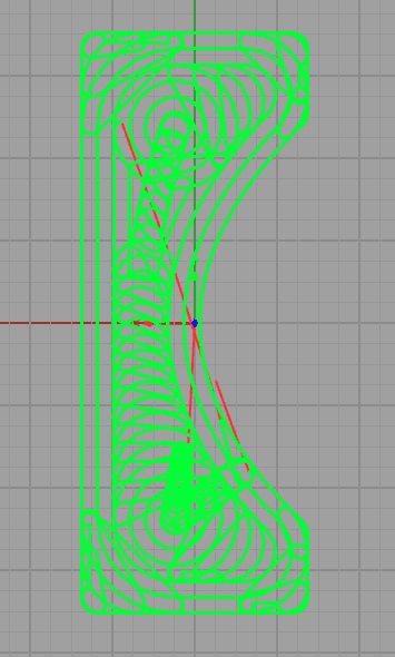
HSM toolpath for pocket roughing…
As you can see, the two toolpath styles are quite different. Avoiding corners accounts for HSM’s ability to drive the tool through the material so much faster and harder. The difference can radically improve your job's metal removal rate.
Keep in mind that HSM toolpaths often also have an advantage for tool life, especially for harder workpiece materials.
The other CAM roughing feature we considered is Rest Machining. This is the ability to cut a pocket with a larger roughing tool that can’t clean out all the corners, and then to go back with a smaller tool that can get into all the crevices and do so without recutting the areas that the larger endmill already dealt with. The small cutter is there to machine “the rest”, hence “Rest Machining.”
Here is a typical example of Rest Machining from OneCNC:
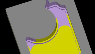
The yellow areas were roughed out with a larger cutter but it can’t get into the purple areas, which have to be machined by a smaller cutter.
Both Rest Machining and HSM toolpaths are premium CAM features. Not every package has both of them or even one of them. Sometimes it is an extra-cost upgrade. As you can see from the graph above, they can make a significant difference. But which one is better?
Looking at the chart, swapping to an Indexable End Mill for our rougher sped things up by 425% whereas just being able to run the same size endmill faster via HSM only got us to 105% faster–about twice as fast versus four times faster. If you had to choose one CAM feature or the other, Rest Milling looks like a win over HSM, though it has been around longer and is not as sexy.
Of course if you run both, you’ll get all the way to our top category of indexable plus HSM, which was over five times faster than just using the same endmill to rough and finish.
All of these tests were conducted against the G-Wizard Generic VMC machine profile and with the default small 2 ” by 3″ pocket with a 1/4″ depth and 1/8″ radius corners in the pocket. Changing these variables significantly may change the overall tradeoffs here–that’s why you need a live calculator to tell for sure what’s best for your particular machine, tooling, and situation.
Another type of toolpath that can giver higher MRR's is called Plunge Milling.
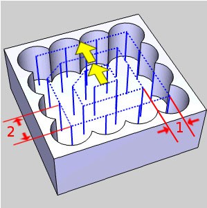
Plunge Milling a Pocket – Image courtesy of BobCAD…
Plunge milling relies on the idea that machines are more rigid in the vertical direction. So, if the limiting factor is rigidity, you can potentially overcome that and increase Material Removal Rate's by using plunge milling.
Optimizing Depth of Cut and Width of Cut
You've chosen a tool, hopefully using the Golden Rule. You are ready to hog the heck out of that part, right?
Not quite. Next up is optimizing depth of cut (axial depth of cut) and width of cut (Stepover or radial depth of cut). These are two of your most powerful variables to achieve higher mrr, yet many CNC'ers will set them purely by rules of thumb. That's a big mistake in the overall scheme of things.
Please check it out.
Determining the Ideal Feed Rate and Cutting Speed for Material Removal Rate
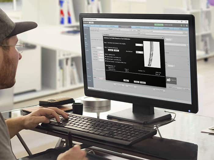
By now you're ready to figure out the Feeds and Speeds for your tool given the optimal combination of Depth of Cut and Stepover. Once again, we have created software that can solve this problem for you. It's called G-Wizard Calculator, and you can get a free trial just by signing up.
Don't Forget Rough Cutting
While we're on the subject of roughing and Material Removal Rates, let's don't forget Rough Cutting. The first step in many machining operations is to rough cut a big piece of raw workpiece material down to the size you will put on the CNC Machine.
If we think about rough cutting as part of the roughing process, it doesn't take long to realize it is the fastest way to remove lots of workpiece material.
A bandsaw can typically hold about 1/10 of an inch. So, the more of your part you can cutout on that bandsaw, the more of your peripheral roughing only has to remove 1/10" or so of workpiece material.
But bandsaws are clumsy and not automated enough to capture the full potential here.
How about a Waterjet or Industrial Laser?
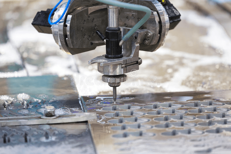
A typical Waterjet can cut with 0.003 - 0.006" accuracy on parts less than 1" thick. Thicker parts are less accurate. Now you've eliminated the roughing step on the Waterjet cut walls altogether. That brings it down to a finishing pass.
Of course this isn't a panacea. You can't cut pockets (only through cavities) with a Waterjet or Laser, for example. But you can eliminate quite a lot of work on the average 2 1/2D part with such a technique. Perhaps even enough to warrant having a Waterjet or Laser in your own shop to prep parts.
So, the final thing to optimize for your Material Removal Rate and roughing strategy is rough cutting parts before they even go on the CNC Machine.
Conclusion
It's been something of a journey, but I hope I've given you some new ideas for how to optimize your Material Removal Rates. Be sure to click through the various links for fully in-depth coverage. Lastly, here are some more articles from our archives that will help you achieve higher Material Removal Rate's:
15 Useful Features of G-Wizard for Higher MRR Rates
Material Removal Rate FAQ
How material removal rate is calculated?
The material removal rate when milling can be calculated as: MRR = Depth of Cut x Width of Cut x Feed Rate.
What is the unit of material removal rate?
Material Removal Rate is the amount of material removed per unit time, so it's units are typically with cubic inches per minute or cubic mm per minute.
What is MRR in machining?
MRR is the abbreviation for Material Removal Rate in machining operations. For example the material removal rate when milling is: MRR = Cut Width x Cut Depth x Feed Rate
How do you calculate MRR in drilling?
Here is the Material Removal Rate Formula for Drilling: MRR = pi * (Hole Diameter ^2) * Feed Rate/4 `
Be the first to know about updates at CNC Cookbook
Join our newsletter to get updates on what's next at CNC Cookbook.