There’s some lingo associated with Feeds and Speeds, but it’s not hard to learn.
The “Speeds” portion of the Feeds and Speeds combo refers to your spindle rpm. Determining the correct Speeds for a job is largely a question of determining how fast the tool can be spun without overheating it in the material you’re cutting. Or, in soft materials like plastic and wood, overheating may burn or melt the material.
In a series of experiments performed early on in machining, it was determined that your spindle speed is the biggest determiner of your tool’s life. Running too fast generates excess heat (there are others ways to generate heat too), which softens the tool and ultimately allows the edge to dull. We’ll talk more in our series about how to maximize tool life, but for now, consider your spindle speed to be largely about maximizing tool life. Be very careful about exceeding recommended spindle rpms!
“Feeds” refers to the feed rate, in some linear unit per minute (inches per minute or mm per minute depending on whether you’re using the Metric or Imperial system). Feed rate is all about the trade off between maximizing your material removal rate and being able to extract chips from the cut. Material removal rate is how fast in cubic units your CNC machine is making chips–the faster the better for most machinists, right up until it creates problems. The most common problem is tool breakage or chipping when you feed too quickly.
The tool breaks because the chips jam up in the flutes, the cutter binds up, and pretty soon it breaks.
I’m a Beginner, How About if I Just Run the Machine Super Slow? (Big Mistake!)

Wait, running too slow is bad?
It’s a common misconception that you can “baby” the cut in order to be ultra conservative. Just run the spindle speed super slow and the feed rate slow too and you won’t break anything, right? Well, not exactly. Here’s some examples of what can happen if you run too slowly:
– If you reduce your spindle speed too much relative to the feed rate, you’re forcing the flutes of your cutter to take off too much material. The endmill is being pushed too fast into the cut and the chips get too big. You can easily break a cutter this way.
– If you reduce your feed rate too much relative to spindle speed, you will soon cause your cutter flutes to start “rubbing” or “burnishing” the workpiece instead of shearing or cutting chips. Many machinists will tell you the fastest way to dull a cutter is just to run it with the spindle reversed and make a pass, but having too slow a feed rate creates a similar effect. We’ll talk more about how this happens later in this Master Class, but suffice it to say that running too slow is just as hard on your cutters as running them too fast, if not harder.
That's a real surprise, right?
The Sweet Spot for Feeds and Speeds
Yes! That’s exactly right, there is a Sweet Spot for every cutting operation.
If we can hurt cutters by going too fast or too slow, then there's that happy medium-the Sweet Spot.
It’s not a point that has to be hit exactly, but at the same time, it is not very large either, and there are penalties if you miss it completely. The more difficult the material you’re cutting, the smaller the sweet spot and the greater the penalties. Once you know where the Sweet Spot is, you can tweak your cutting parameters within that envelope to maximize Material Removal Rates, Surface Finish, or Tool Life. In fact, you can often maximize any two of the three, just not all three at once.
Let’s take a look at the sweet spots for different goals, as well as the danger zones: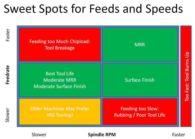 This chart is relative, meaning you can’t assume anything about the proportions or scale. Just look at the positions of the regions relative to one another, and relative to the idea of faster and slower spindle speeds and feed rates. For example, Feeds and Speeds for Wood have a much larger sweet spot than feeds and speeds for metals.
Let’s consider the different labeled zones, left to right, top to bottom:
Feeding too Much Chipload: As we’ve discussed, when you feed too fast for a given spindle rpm, you’re likely to break the tool. The more you exceed the appropriate speed, the more likely. At some point, you’ll always break the tool. Consider the absurd case where spindle rpm is zero and you rapid the tool into the work. Pop! Just broke another tool. By the way, I snuck in a bit of jargon, "Chipload". Chipload is measured as units per tooth. For example, inches or mm per tooth of the cutter. Feedrate is dependant on spindle rpm. If we change the rpm we must change the feedrate to maintain the same chipload. And that's the advantage of chipload-it's one number that works for all rpms. Congrats, you've now learned a new term.
MRR: MRR stands for "Material Removal Rate," another piece of machining jargon. It measures cubic units of chips made per time interval. For example, cubic inches per minute. Running the spindle as fast as we can without burning the tool, and feeding as fast as we can without breaking the tool is the sweet spot for maximum material removal rates. If you’re manufacturing, this is where you make money by getting further up and to the right than the competition. We increase Material Removal Rates in order to reduce the amount of time it takes to machine a part.
Too Fast: Too much spindle speed will generate excess heat which softens the tool and dulls it faster. There are exceptions and mitigating circumstances we’ll talk about in more advanced installments.
Best Tool Life: Slowing down the spindle a bit and feeding at slightly less than appropriate for maximum MRR gives the best tool life. We’ll talk more later about Taylor’s equations for tool life, but suffice it to say that reducing the spindle rpm is more important than reducing the feed rate, but both will help.
Surface Finish : Reducing your feed rates while keeping the spindle speed up lightens the chip load and leads to a nicer surface finish. There are limits, the biggest of which is that you’ll eventually lighten the feed rate too much, your tools will start to rub, and tool life will go way down due to the excess heat generated by the rubbing.
Older Machines:So your spindle speed has come way down, and in addition, so has your feed rate. You’re probably on an older machine where you can’t run the kind of speeds you need to take advantage of carbide tooling. You may need to switch to HSS (High Speed Steel, a material used in cheaper lower performance cutters). It comes as a surprise to many that there are areas of the feeds and speeds envelope where HSS can outperform carbide, but it’s true, depending on your machine’s capabilities and the material you’re cutting. Check the article “Is Carbide Always Faster than HSS” for more information.
Feeding Too Slow: What happens if feed rate is too low? As discussed, feeding too slow leads to rubbing instead of cutting, which can radically shorten your tool life and is to be avoided. Poor tool life with too slow feed rates is caused by rubbing and potential work hardening if the material is susceptible to it.
Now that you know how the sweet spots break down, you’ll have a better idea how to steer your feeds and speeds to the desired results.
I always find it's easier to remember concepts with a visual, so hopefully the Sweet Spot diagram will make it easier for you too. Go ahead and print it out and tape it up somewhere prominent in your shop if it helps further.
Chip Load: Chip Thickness per Tooth
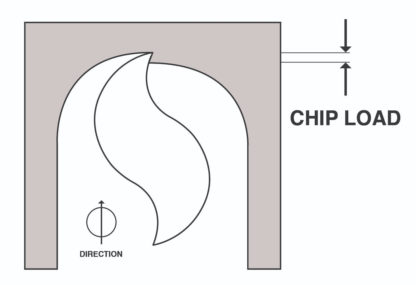
Chipload is the thickness of the chip being sliced off by your cutter. Image courtesy of Onsrud.
I briefly described chipload above, but let's dive in a little deeper (don't worry, not too deep).
While cnc feed rates are specified in length units per minute, the more important measurement is something called “Chip load”. Think of a chip as looking something like a comma in cross section, or perhaps an apostrophe. One starts big and gets smaller at the end. The other starts small and gets bigger at the end. We’ll ignore that difference for a moment, though it is important as we shall see later. If we measure the thickness of the chip at its thickest point, that's the chipload. Simple, right?
Chip load is a measurement that is independent of spindle rpm, feed rate, or number of flutes. It tells how hard the tool is working. That’s a very useful thing, as you could imagine. Hence, manufacturers and machinists typically like to talk about chip load for a particular tool.
You can see that a tool with more flutes (cutting edges) has to be fed faster to maintain a particular chip load for all the flutes. Since each tooth is going to take a cut every rotation, a tooth has only a fraction of a rotation in which to cut a chip that reaches the chip load thickness. During the time it takes to rotate the next tooth to start cutting, the tool has to have moved far enough to shave off a chip that is thick enough. Hence, tools with more flutes can be fed faster. A 4 flute endmill can be feed twice as fast as a 2 flute, all other things being equal.
By now you're thinking, "What if I just by a 32 flute cutter, I can really fly with that thing, right?" Not so fast. The number of flutes you can use in a material is limited in many cases. In aluminum, for example, the cutter makes big thick chips that curl to make themselves even fatter. You can only run 2 or 3 flutes or your cutter will choke on the big chips and break. As a rule of thumb, most things other than aluminum can take 4 flutes and aluminum 2 or 3. Lots of exceptions there, but if you're a beginner, stick to that rule of thumb for now.
Why do Tools Break from Too Much Chip Load?
You can imagine that forces simply become too great if a tool tries to take too much “bite” by having too much workload. This can chip or break the cutter. But there is a second issue that comes from too much chip load–the chips get bigger and eventually can’t get out of the cutter’s way.
Beginning machinists probably break more tools because they don’t get the chips out of the way fast enough than because the force of the feed is breaking the tool. If the cutter is down in a deep slot, the chips have a particularly hard time getting out of the way. We use air blasts, mists, and flood coolant to try to clear the chips out of the way, but if they’re way down a hole or slot, it makes it that much harder, and we have to reduce speed. Making matters worse, chips always take more room once they’re chips than the equivalent weight of material takes as a solid. The only place they have to go is gaps between the flutes of the cutter. Of course, the more flutes we have, the less space there is in the gaps.
Can you see the point of diminishing returns coming?
This is a huge role of Feeds and Speeds Calculators like G-Wizard. The tool manufacturer's data gives you one or two sample chiploads, or a range of chiploads. But a calculator like G-Wizard will nail down exactly what kind of chipload you can use based on the cutter's recommended chipload and the conditions of how far down the hole the cut is (Depth of Cut) and how much of the cutter is working in the cut (Cut Width or Stepover). These calculations are difficult to do without a fair amount of math, hence Feeds and Speeds Calculators can be real time (and tool) savers.
Surface Speed: How Fast the Tool Slides Against the Workpiece While Cutting
You’ll come across the term “Surface Speed” pretty quickly with Feeds & Speeds because we use it to determine the right spindle rpm. You may also hear Surface Speed referred to as “Cutting Speed”.
When specifying the operation of a tool, surface speed goes hand in hand with chip load. Just as chip load is a better way to talk about cnc feed rate because it is independent of so many factors, surface speed is a better way to talk about spindle rpm. Imagine that instead of a rotating cylinder with cutting edges, your tool was a flat piece of metal slid against the workpiece. The recommended speed to slide when cutting is the surface speed.
Here’s the visual:
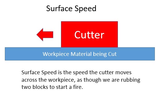
Visualizing Surface Speed…
Surface speed is measured in linear units per minute: feet per minute (SFM) for Imperial, and meters per minute in Metric.
You can’t really cheat on Surface Speed. It is what it is and exceeding the manufacturer’s recommendations is sure to reduce tool life fairly drastically except for some very special HSM (High Speed Machining) and advanced coolant (high pressure through spindle coolant) cases you should only worry about when you’ve mastered the basics.
To give you an idea, here is a cutting speed chart (surface feet per minute chart) that shows you the surface speed in feet per minute for typical materials when cutting with an HSS (High Speed Steel) End Mill:
Cutting Speed Chart giving Surface Speeds for HSS End Mills in SFM
Material
Surface Speed (SFM)
Aluminum – Wrought (6061)
250
Brass
200
Cast Iron – Ductile
90
Cast Iron – Gray
100
Copper Alloy – Wrought
120
Magnesium Alloy
250
Stainless Steel
30
Steel – Mild
110
Steel – Hard Alloy
60
Steel – Tool
60
In general, Surface Speeds are higher for softer materials and slower for harder / tougher materials. Carbide End Mills can tolerate much higher speeds than HSS (High Speed Steel), which is why carbide is so popular in machining. In fact, the transition from HSS to Carbide was the first big productivity increase in the history of machining, with the transition from manual to CNC being the second big productivity increase.
By the way, this is another thing G-Wizard Feeds and Speeds Calculator can help with. It has a huge database of materials along with surface speeds. We're talking not just aluminum versus steel, but alloys and even conditions (hardened, annealed, etc.) of the alloys. There are hundreds of species of wood alone, for example.
The Interaction of Surface Speed and Spindle RPM
Consider this table which shows tool diameter versus surface speed at 10,000 rpm:
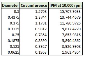
Surface Speed vs Diameter at 10,000 rpm…
If we keep rpms constant, Surface Speed is directly proportional to diameter. The 1/16″ endmill at the bottom is travelling 1/8 as fast in terms of Surface Speed as the 1/2″ endmill at top. Hence, to achieve a given Surface Speed, small tools will have to spin faster and large diameter tools will have to spin slower.
Here’s the classic surface speed or sfm formula they teach in shop classes:
Spindle RPM Formula = (12 * SurfacceSpeed) / (PI * CutterDiameter)
There are a number of reasons why this formula is idealized and not the best for real world use, but you get the idea.
Where Can I Find Surface Speed and Chipload Information?
Traditionally, this information comes from your end mill manufacturer's tooling catalog. A more generic source would be something like Machinery's Handbook.
A much easier place to get and use the information is in a Feeds and Speeds Calculator, like our G-Wizard Calculator. Check out the G-Wizard screen:
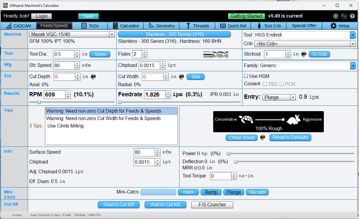
Moving from top to bottom, the following rows have Surface Speed or Chipload information (rows are identified via the blue on black labels in the lefthand columns):
Mfg: This column is for starting Surface Speed and Chipload, usually taken from the Manufacturer, hence the "Mfg" row name. G-Wizard has excellent defaults if you don't fill in the values in this row. In fact, the only good reason to fill them in is if you're using premium cutters and need every last ounce of performance from them. Otherwise, take it easy and just use G-Wizard's defaults. You won't break your tools with the defaults, honest.
Info: This row tells you a bunch of live statistics on the actual cut. This includes the actual Surface Speed and Chipload as well as the Adjusted Chipload for this cut. Why are these numbers different than the Surface Speed and Chipload in the Mfg row? It's because these numbers are adjusted for cut conditions. If we are cutting super deep, it's harder to get rid of the chips, so we need to reduce the Surface Speed and Chipload from theoretical maximums to account for the more difficult cut. You can override G-Wizard's calculations, but unless you're an advanced user who knows just what they're doing, it isn't recommended. The "Adj. Chipload" is a further adjustment for something called "Chip Thinning" that we'll cover in Lesson 3.
The bottom line is you don't have to worry about Surface Speed or Chipload when you're using G-Wizard. It has smart defaults and it adjusts them according to cut conditions. If you really want the maximum performance from your cutters for production reasons, G-Wizard can accept that information and further refine it for even better results. We'll explain how that works in a future Lesson.
What's that? You don't have G-Wizard yet?
Good news: we offer a free 30-day trial. You really should take advantage of it!

Go ahead and grab a G-Wizard free trial. It'll make it easy for you to experiment with the concepts in this course so you understand and can apply them better.
You can go on to Lesson 2: How to Use a Feeds and Speeds Calculator or wait for it in next week's email.
More Feeds and Speeds Calculators
-
G-Wizard Feeds and Speeds Calculator
-
Milling Speeds and Feeds Calculator
-
CNC Feed Rate Calculator
-
Chip Load Calculator
-
Simple Feeds and Speeds Calculator
-
Lathe Feeds and Speeds Calculator
-
Drill Feeds and Speeds Calculator
-
Tapping Feeds and Speeds Calculator
-
Master Feeds and Speeds Calculator List
Be the first to know about updates at CNC Cookbook
Join our newsletter to get updates on what's next at CNC Cookbook.