Chip Load Calculator
Feed Rate: IPM (inches / minute)
Spindle Speed: RPM
Number of Flutes (Teeth):
Feed/Tooth (Chipload):
Chip Load Formula:
IPT (inches / tooth) CHIP LOAD = Feed rate / (RPM x Number of teeth)
Chip Load: Chip Thickness per Tooth
While cnc feed rates are specified in length units per minute, the more important measurement is something called “Chip load”.
Think of a chip as looking something like a comma in cross section, or perhaps an apostrophe. One starts big and gets smaller at the end. The other starts small and gets bigger at the end. We’ll ignore that difference for a moment, though it is important as we shall see later.
Chip load is a measurement that is independent of spindle speed (rpm), feed rate, or number of flutes that tells how hard the cutting tool is working. That’s a very useful thing, as you could imagine. Hence, manufacturers and machinists typically like to talk about chip load for a particular cutting tool.
You can see that a cutting tool with more flutes (cutting edges) has to be fed faster to maintain a particular chip load. Since each cutting edge is going to take a cut every rotation, a cutting edge has only a fraction of a rotation in which to cut a chip that reaches the chip load thickness. During the time it takes to rotate the next cutting edge to start cutting, the tool has to have moved far enough to shave off a chip that is thick enough. Hence, tools with more flutes can be fed faster.
A 4 flute endmill can be fed twice as fast as a 2 flute, all other things being equal.
Something to know–aluminum is typically limited to 2 or 3 flutes on an endmill. Why? Because chiploads are high (it’s an easy material to cut) so the chips are thick and they curl. They will jam the flutes if they’re too small. By limiting flutes to 2 or 3, the flutes can have more clearance for the big chips.
Why do Cutting Tools Break from Too Much Chip Load?
You can imagine that forces simply become too great if a cutting tool tries to take too much “bite” by having too much workload. This can chip or break the cutter.
But there is a second issue that comes from too much chip load–the chips get bigger and eventually can’t get out of the cutter’s way.
Beginning machinists probably break more cutting tools because they don’t get the chips out of the way fast enough than because the force of the feed is breaking the cutting tool.
If the cutter is down in a deep slot, the chips have a particularly hard time getting out of the way. We use air blasts, mists, and flood coolant to try to clear the chips out of the way, but if they’re way down a hole or slot, it makes it that much harder, and we have to reduce speed. Making matters worse, chips always take more room once they’re chips than the equivalent weight of material takes as a solid. The only place they have to go is gaps between the flutes of the cutter. Of course, the more flutes we have, the less space there is in the gaps.
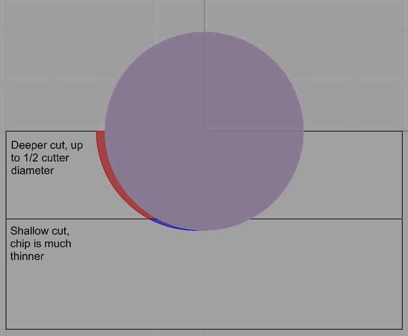
Two Odd Geometry Effects of Cutting Tools: Rubbing and Chip Thinning
There are a couple of odd geometry effects that have to do with chip load. The short summary is if you lower the feedrate too much, or lower the cut depth too much, you can get into trouble. In fact, it can be pretty big trouble too. I'm not going to present all the details here. You can look to our special article on chip thinning and rubbing for details. You should know that the above free calculator can't account for either factor, but our G-Wizard Feeds and Speeds Calculator covers both.
G-Wizard includes a built-in rubbing warning to keep you out of trouble:
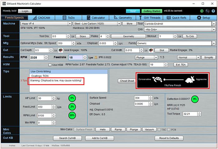
I want you to notice the two areas I’ve flagged with a red rectangle outline.
On the right, you see G-Wizard’s “Tortoise-Hare” slider. It moves cuts from most conservative (full tortoise) to most aggressive (full hare). The most conservative position is calibrated to be the slowest you can feed without rubbing. It’s handy, both to know where the limit is, but also to get the nicest possible finish. We’ll talk more about the Tortoise Hare and Finishing vs Roughing Feeds & Speeds soon, but I wanted to get that out there.
Now I manually reduced the feedrate further after setting it to the Fine Finish position, so now we are rubbing. And you can see the lefthand red rectangle shows a warning message that these settings may cause rubbing. If you use a tool like G-Wizard, you won’t have to worry about rubbing much because the software is looking out for you.
For a complete chip thinning walkthrough using G0Wizard, see our article.
You'd be surprised at how helpful managing these two factors can be for increasing your Tool Life and reducing your cycle times.
More Feeds and Speeds Calculators
-
G-Wizard Feeds and Speeds Calculator
-
Milling Speeds and Feeds Calculator
-
CNC Feed Rate Calculator
-
Chip Load Calculator
-
Simple Feeds and Speeds Calculator
-
Lathe Feeds and Speeds Calculator
-
Drill Feeds and Speeds Calculator
-
Tapping Feeds and Speeds Calculator
-
Master Feeds and Speeds Calculator List
Feed Per Tooth Chart (Chip Load / IPT)
Milling Chiploads (Feed Per Tooth Chart) for HSS End Mills
Material
Chipload (IPT)
Aluminum - Wrought (6061)
0.005 - 0.010
Brass
0.005 - 0.010
Cast Iron - Ductile
0.004 - 0.008
Cast Iron - Gray
0.002 - 0.006
Copper Alloy - Wrought
0.004 - 0.008
Magnesium Alloy
0.005 - 0.010
Stainless Steel
0.002 - 0.006
Steel - Mild
0.002 - 0.010
Steel - Hard Alloy
0.002 - 0.006
Steel - Tool
0.002 - 0.006
Note: Chipload should be adjusted for tool diameter. Smaller tools tolerate much lower chip loads! You can look this up in the manufacturer's catalog, or we can help.
Be the first to know about updates at CNC Cookbook
Join our newsletter to get updates on what's next at CNC Cookbook.