Here's a few dozen CNC Project Ideas to mull over for your next big thing. There is always something more you'd like to beg, buy, borrow, build, or steal! Here my list of projects I'd like to someday tackle in my shop. The easier projects are below and then there's a whole other section filled with more ambitious projects below. Also, don't forget our page of model engine projects!
Beginner's CNC Project Ideas - Wish List of Easier Projects
These projects are perhaps better suited to beginners or for those who want to see results sooner.
Mill
Fixture Plate

Fixture plates make it easy to align things on your mill table because you have a grid of precision dowel pin holes. Put your vises and fixtures on subplates with a matching grid and you can drop them on the table and have them be very closely aligned right from the start.
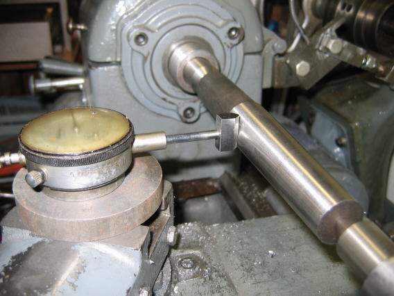
_**Handy Gadget to Indicate
Parts in the Lathe Chuck**_
I liked this little video (other than leaving the key in the chuck, don't do that!):
He just uses a ball bearing mounted on the QCTP to gently "nudge" parts into proper alignment
You'll want to be very careful with this technique-don't fire up the spindle to a very high rpm, for example. But, it looks like a real time saver if properly done.
There are a couple of great tips here. Aside from aligning the part in the chuck with the ball bearing, the use of circular pieces instead of a dovetail on the QCTP is also quite interesting. It also looks like he keeps that indicator on a permanent holder on the lathe's backsplash where it is handy to get to.
Dodecahedron
These aren't really useful for anything I can think of, but they sure are cool!
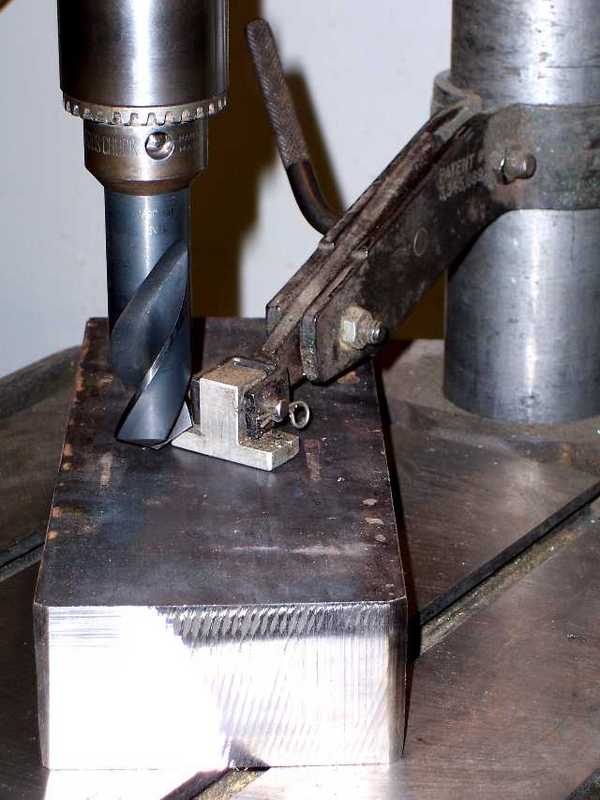
Mill Table Tramming Aids
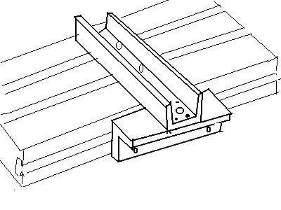
These are aids for tramming tooling, such as your milling vise, not the mill head. My favorite is the idea of a tramming "key" to be installed in the jaws of your milling vise. The idea is due to John Stevenson and looks like this:

Insert the U-shaped key in your vise jaws, tighten the jaws, press the key against the top T-slot edge, and tight down the vise. Nothing could be faster or simpler!

Here are rough dimensions for a key to fit a Kurt D675...
One fella mentions this is a handy way to quickly square things on his mill table:
He said he made it up and machined the edges of the T-Square so that they would be true to the table. Seems like a pretty slick idea to get a vise or other item lined up quick. He did say if he had it to do over again he'd use a piece of 1" square bar.
I have seen someone else recommend making up some pegs that can be inserted in the table slots to line things up. That doesn't seem like it would be as accurate, although I did get an email from someone who had used the round pegs on the vise or in the T-Square itself and said it worked great.
Here is another approach recommended by a talented Australian HSM:

PerpEdge for aligning things on the table...
He calls it a "PerpEdge". He lines it up with a square and then double checks with an indicator. Looks easily made. I'd like to
see how well this sort of thing might work for lining up my vises on the mill table.
Another approach is to install a key on the bottom of the vise that will mate tightly with the T-Slots on the table. I liked this
description from the HSM board of how to install a key on a
the base of a milling machine vise so that it will always be in
tram on the table:
If the vise does not already have a key slot in
the base, install a tight fitting key in one of the table's T
slots. Invert the vise and clamp it to this key. Mill a keyway
in the base of the vise, usually through the slots for the hold
down slots, that corresponds to the table slot. Install a key
in this slot with socket head cap screws.You might have to shim the fixed jaw for the ultimate in tram,
but the vise will always be reinstalled in the same position.
Another thought, if you don't want to modify the
vise, is to make a tramming fixture that you clamp in the vise jaws.
Said fixture would mate with the T-slot precisely enough to ensure
tram as the vise is being bolted down.
Consider using a subplate with Sine
Keys made by Reid as another approach.
Here is another approach that uses
low temperature Cero alloy that sounds interesting:
My Method,for dead nuts accuray
and repeatability, and no ‘precise' machining to get it.
Make a Subplate. (I use 3/4 Aluminum )
Drill holes for hold down bolts through/into the keyways.
Set the vise on the plate roughly in the setting, without clamping.
mark the locations of the vise keys...roughly.
remove the vise and mill 1/4" deep slots for keys, except make
the slots long enough to be exposed outside the vise..maybe 3/8"
/
now mount the vise and indicate Very close, then pour in some
low melting alloy , like Cerrocast,Cerro Safe, Cerralloy. when
the melt protrudes above the slot, slap a parrallel down on it,
forcing the melt upinto the vise keyways, and chilling it. You
now have a permanent set of keys, that accurately set the vise
to plumb EVEN if the keyways do not match !. If you remove the
vise, the keys can go with it for other tooling allignment like
a rotary table. Just keep track of which key is which . The Cerro
Alloy is hard and it really works guys.
If you remove a vise and the mounting hole is exposed during another
operation, take an old Christmas candle ,and jam it down the opening
and cut it off even with the subplate . this seals it from chips,
but is easily dug out and it lubes the screw when you replace
the vise.
Mill Vise Caddy

Here is a nifty accessory to save humping that heavy vise on and off the mill table.
It's so nicely made, isn't it? You clamp the vice jaws onto the thing and you can lift the vise off and swing it out of the way. It almost seems to me like something slightly more general would let you keep a bunch of vises, rotary tables, and other goodies on a shelf behind the mill and bring them on and off as needed.
You can buy one already made from SPI (via MSC or other dealer) which calls the product a "Mill Vise Caddy." Cost, $339.
The magnetic chip shield is also handy, and could be easily made.
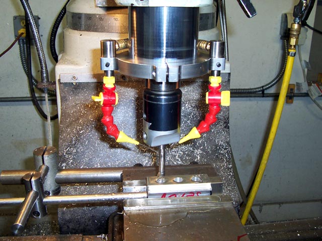
The Widgitmaster's Coolant Collar...
A spindle coolant collar is a very handy thing indeed. Firstly, it provides a convenient way for the coolant nozzles to track the activity of the mill in a more elegant and permanent way than the magnetic versions that are available. This ensures that once the nozzles are lined up properly, they'll do the right thing wherever the spindle wanders. Second, there are numerous reports that the darned things can also help cool down your spindle bearings, which seems like a darned thoughtful thing to be doing as well to me.
I have started an Idea Notebook with pictures of a number of different coolant systems along these lines.
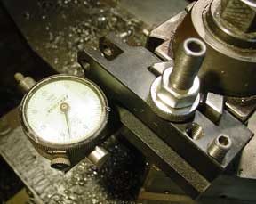
QCTP Indicator
Holder

Someday in the not too distant future I plan to give my lathe a tune up. I want to check spindle runout, adjust the preload on the spindle bearings, check the headstock and tailstock alignments, and generally give it a little TLC.
One of the things that I've been seeing for a long time and thinking I need to build is a QCTP holder with an indicator in it. I
recently saw another one and thought I'd do a little roundup article here so I've got the details all in one place. One of these will be handy for the lathe tuneup as well as for indicating in the 4-jaw chuck.
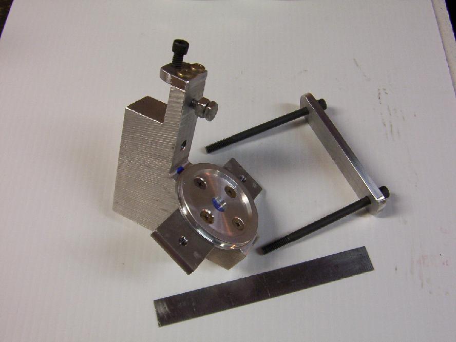
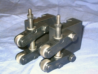
Needs no Dovetail Cutter
If you don't have a dovetail cutter for making QCTP holders (I made one, it isn't hard!), you might consider this fellow's approach of just doing it by milling the dovetails as separate parts:

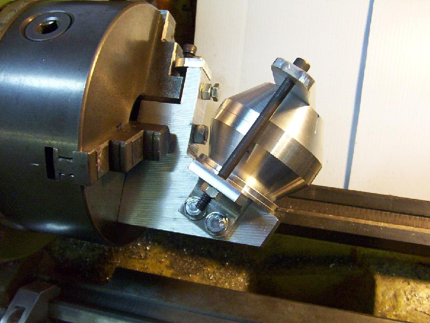
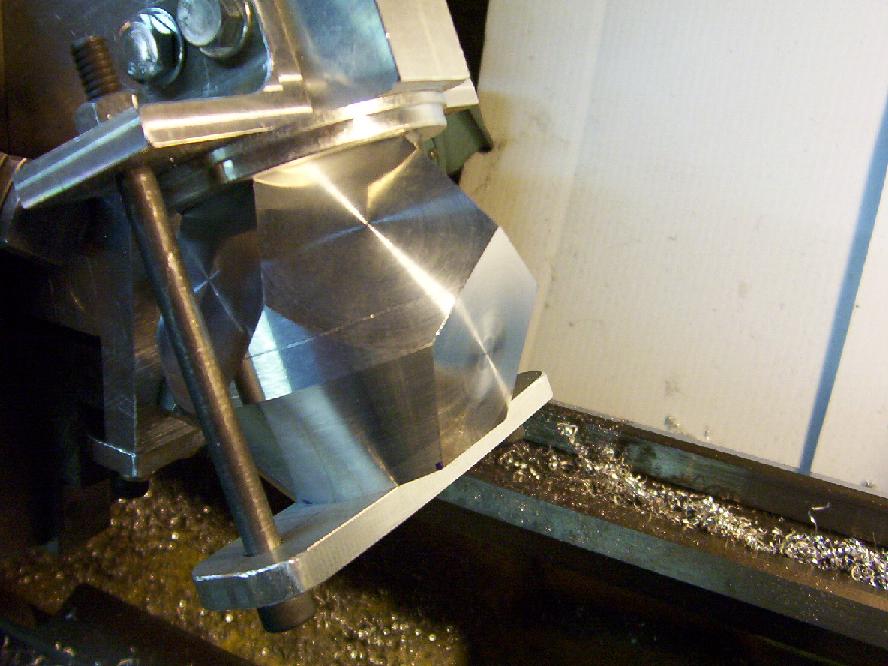
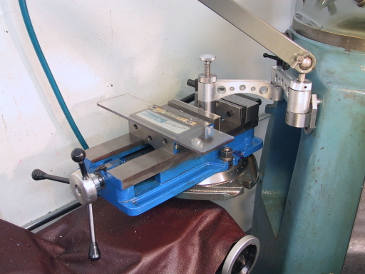
Using a Tilting Vise Fixture to Mill the Dovetails...
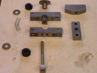
The Components. Note How the Dovetails Are Bolted to the Holder...
"Flapper" For Irregular Shapes
Marv Klotz gave us the "Flapper" design for dialing in irregular shapes or square stock in the 4-jaw:

This one just uses a magnet to
attach itself...
JTiers Approach to Irregular Shapes
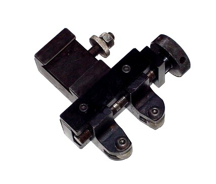
5Bears Indicator Holder
5Bears (the Swede) modified an unused QCTP (looks like a knurler) for this purpose:
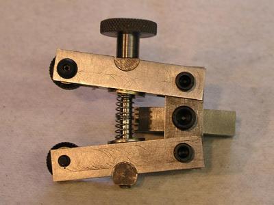
CNCCookbook "Instant" Indicator Holder

As I was writing this, I was staring at an indicator holder that fits onto a height gage I got off eBay. These replace the carbide scriber and can be used to increase sensitivity and accuracy of the height gage. eBay seller discount_machine
(I think that's Shars) has them for $8.95.
If you want one (I ordered a second after seeing how useful they can be), do an eBay search for "HEIGHT GAGE INDICATOR". They only have them on "Buy it now" in their store, so you may have to look carefully.
I took this little gadget together with the QCTP knurler holder (everyone has one and they aren't that hot if you get a scissors knurler, so its great to reuse it) and put them together to get this:

It wouldn't take much to rework the mounting bar so it was just like 5-Bears holder.
Lathe Spindle
Spider

You normally see spindle spiders done up with 4 set screws, but I really liked this this gorgeous spindle bar support system I found on the Chaski board:
The different sized bushings are held in the spindle by the friction of their o-rings. Personally, I'd like a little more positive locking action, but the basic style is very nice and a good idea to prevent the bar whipping as it spins. I've got to add this to my project wish list.
Web Cam
on the Mill and Lathe
Plus Laser
Cross Hairs
S_J_H built this gorgeous housing for a $30 Logitech web cam and posted it on HSM: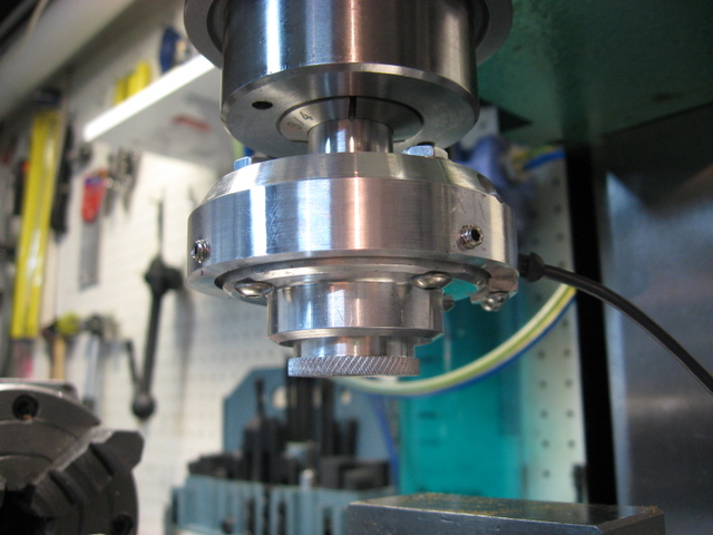
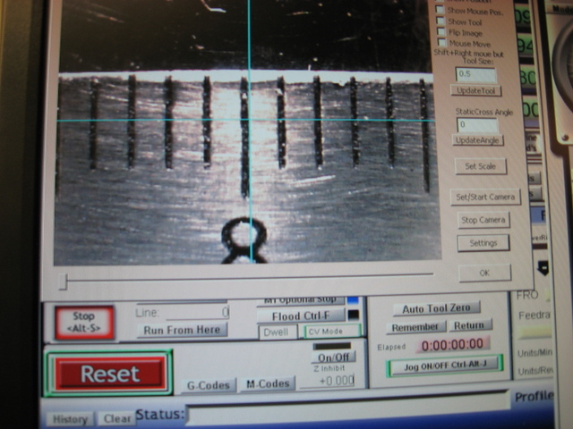
The finished camera inserted in an R8 collet on the mill, and Mach 3 can display the feed from the camera...

Looks like the camera sub-housing has centering
screws...
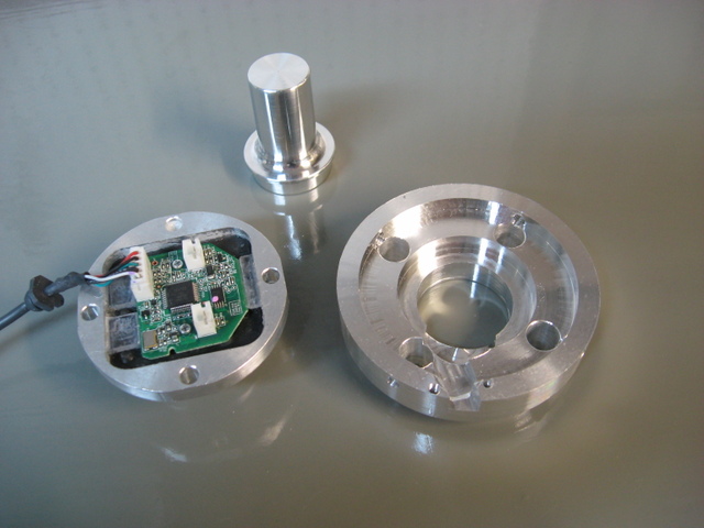
Here are the parts...
Some interesting thoughts:
- S_J_H reports that for sharp edges, he can find a corner within 0.0005". Pretty close! He goes on to say
that punch marks look like craters. - With the manual focus ring, the Logitech would focus down to1/8" from the lens.
- CentreCam is a piece of software that also handles camera feeds for machinework.I think it has more optical comparator functions than Mach does built in.
- Evan suggests an interesting idea if you want to permanently mount the camera. He suggests mounting the camera to focus on an angle, and a laser pointer on another angle. Figure out the height where the laser is centered where the spindle will go and focus the camera on that same point. I like the idea of having both a laser and camera available, and could even see mounting them in the same housing. It would be cool to have a custom button in Mach 3 that automatically puts these at the right height so they're focused dead center of the spindle. I think a laser pointer would be ideal to line up stock within 0.1" prior to firing up a CNC program that will separate the part from the chips inside the workpiece.
- You could also face the laser and video straight down and program the offset from spindle center into Mach 3. This is probably a better idea as it becomes spindle height independent. In practice, you'd hit the button and the table would center on
the laser/video center. You could then jog as desired and hit the button again and you would offset to where the spindle was
centered exactly where'd you'd jogged to with the video. That would be cool!
Here is an inexpensive laser cross hairs mounted on a CNC router courtesy of CNCZone and Aussie member Greolt:
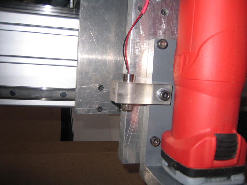
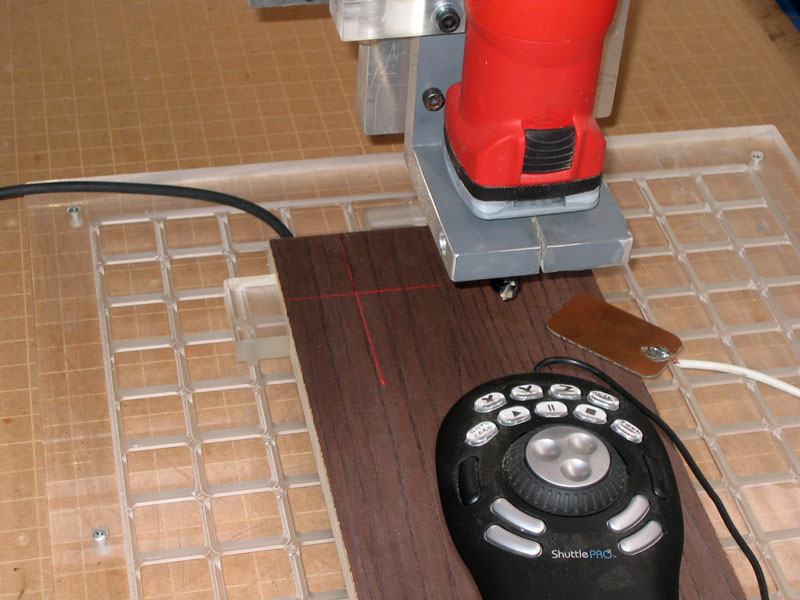
These little cross hairs are available from DealExtreme for $4.30. So cheap!!!
To use with CNC, Greolt
programmed in a button on Mach 3 that compensates for the offset
from the spindle automatically...
But wait, this gets more clever. He added some code to Mach 3 that deals with the fact the laser cross hairs are offset from the spindle.
Here are the controls:

The target toggles the laser on and off. "Laser Zero" zeros the machine at the lasers current position allowing for its offset
from the spindle! The X and Y DRO's let you enter the offset of the laser from spindle center.
Here is what the Mach 3 code looks like to do that:
Xmove = GetUserDRO(1152) ‘X distance DRO
Ymove = GetUserDRO(1153) ‘Y distance DRO
Code "G91 G0 X" &Xmove & "Y" &Ymove
While IsMoving ()
Wend
Code "G90 M9"
DoOEMButton (1008)
DoOEMButton (1009)
The M9 is to turn laser off after the zero. M7 turns it on. He's just using the mist coolant commands to run the laser. The two "DoOEMButton" zero the X and Y. The two DROs are to set the laser offset distance for the script.
Put it all together...
My crazy idea is to combine these two. I want a permanent mounting bracket that holds a housing containing the web cam and integrated laser cross hairs alongside the spindle. We probably want a flip open lens protector as well. I also want it fully integrated so Mach 3 knows about the offset from the spindle. Now you have laser cross hairs when 0.1" is "close enough", and a
0.001" camera comparator for more precise work that is always there.
Wouldn't that rock? I think so.
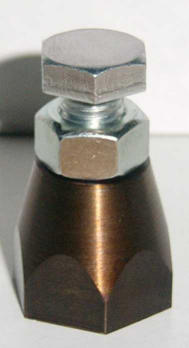
I love this idea that MachineChick published on CNCZone:
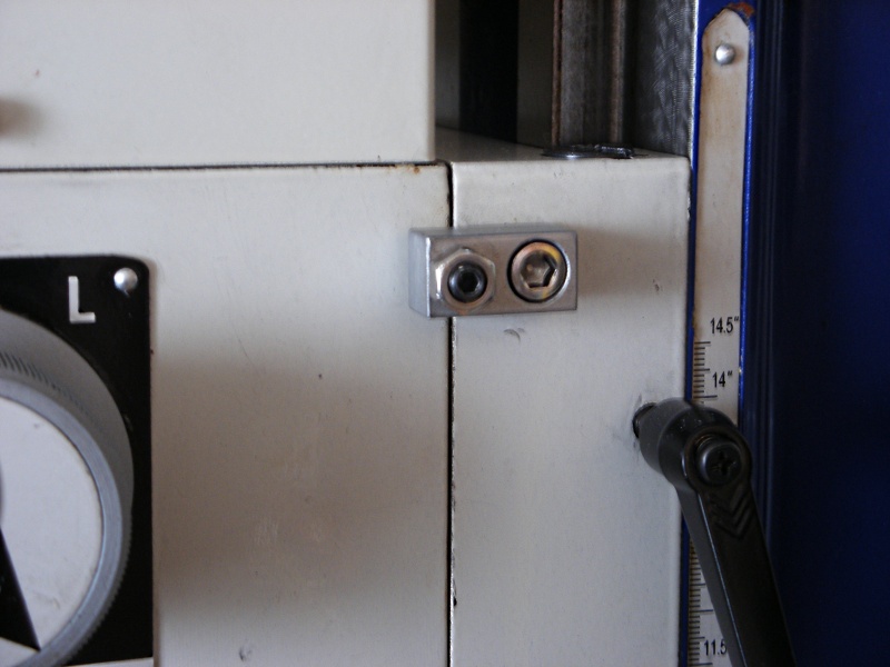
That little setscrew with locknut will apply pressure to the top of the head causing it to pivot smoothly. Makes tramming the head faster, easier, and more precise. I would think it might help hold the head in place a little better too! Mount one on either side so the head can be pushed either way...
High
Speed Spindle Clamped to Mill Quill
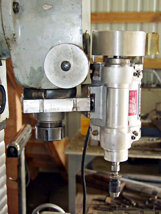
There's
a page of the CNC Cookbook devoted to this idea already...
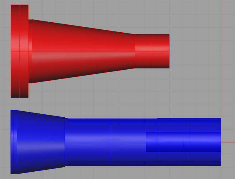
Chuck Adapter for Rotary
Table

This should be a simple project. I basically need to take a circular plate and drill two sets of holes on bolt circles. The first circle will be identical to the bolt circle used by my lathe to mount the chuck backplate to the spindle. To be precise, I want the circle that holds the little faux cam lok's into the back plate:

Backside of adapter, showing bolts through to chuck...
The second bolt circle will consist of 4 holes that are outside the diameter of the chucks. I will use these to bolt the assembly down using the T-Slot system on the rotab. Here is a similar such project done by another machinist:

Front side of chuck ready to bolt down to
rotab...
QCTP Knurling Holder
I need to build a clamp-type knurling tool for my lathe and I need to work on some projects involving the mill to gain experience with it. This one fills both needs nicely.
https://homepage2.nifty.com/mini-lathe/knurl2/knurl-2-e.htm
Aloris Knurling Gadget. It uses dovetail slides
for the knurls...
There is a thread about these over on HSM with a couple of designs. One is very elegant, and the other looks dead easy to build:
**Machinist's
**Jacks
Very nice! Note the square threads...
Another pretty design. Color is a hot oil treatment...

A simple project for an afternoon sometime:
Links
https://homepage3.nifty.com/amigos/screw_jack/screw_jack-e.htm
https://www.davehylands.com/Machinist/Projects/Machinist-Jack/
Shopmade Z-Height Indicator
I was surfing the web the other day, looking for something new to fixate on when I suddenly decided to go visit one of my old haunts: Home Model Engine Machinist. This is a great little board that is focused on building model engines. There are wonderful examples of craftsmanship at all levels to drool over, and while the site is mostly inhabited by manual machinists, there’s a growing amount of CNC information there too. Probably the best thing about the site is it values good comraderie and won’t tolerate the trolls that inhabit and get too much air time at a lot of other sites. These are all folks you’d love to go have a beer with and talk to about the art of machining. If you’ve never visited HMEM, and you have any desire at all to talk to a good audience about machining model engines, by all means check it out.
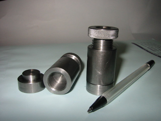
I happened to spot one thread in particular that had some great pictures of a really nice shopmade Z-axis indicator, so I wanted to pass some photos along here as a great example of what you can find without too much effort if you’ll take the time to go explore HMEM. Z-axis indicators are used to precisely touch off a tool in order to determine it’s exact Z position above the workpiece. This is typically done to capture the tool length offset or zero the Z for machining when you manually change tools. You can find more information on this in our article series on Tool Data Management. Suffice it to say that dealing with tool lengths is critical to successful CNC, and this is one way to approach the problem.
This beautiful shopmade Z-axis indicator was done by HMEM member “Maverick”:
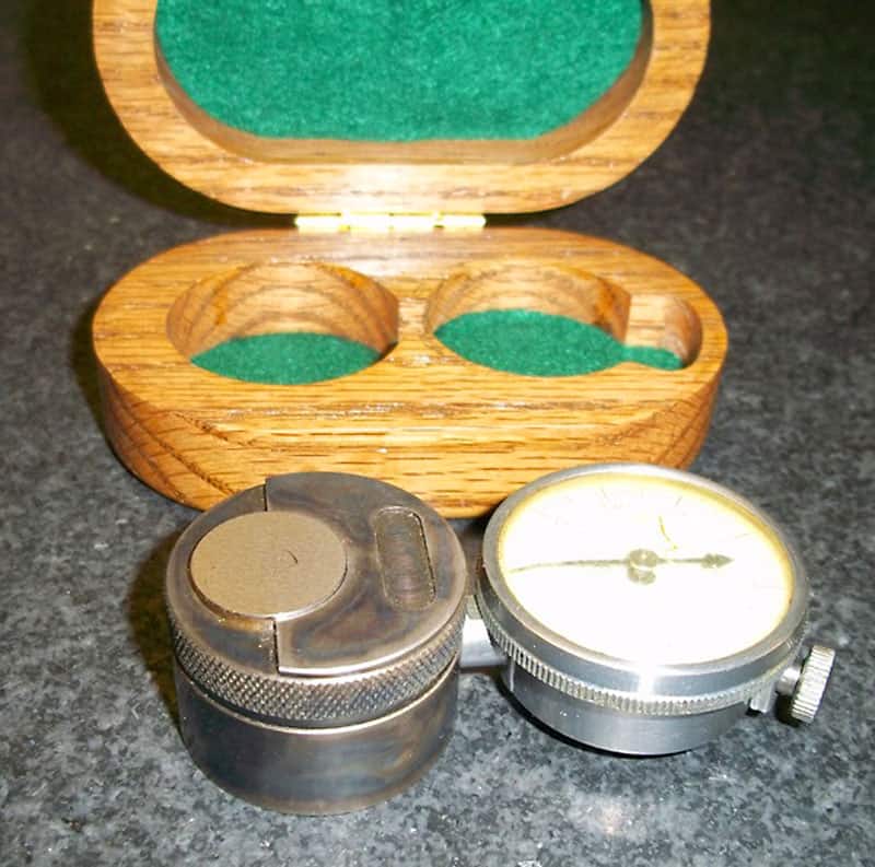
The indicator was color case hardened, and ground so that the bottom of case to plunger is 1.000″ inches high.
Fitted and felt-lined wood case is a nice touch!


The mechanism is simple: the angle ground piston moves the indicator plunger in proportion to how much the piston is pressed down by the tool.
The indicator is held in place by a threaded plug that bears against a brass piece.

Advanced CNC Project Ideas - Wish List of Rash Ideas and Bigger Projects
High Resolution 3D Printer

Now that's High Resolution!
At some point, I want to put together a 3D printer. While the FFF (Fused Filament Fabrication) printers are cheap and cool, I'm captivated by the High Resolution 3D Printers. They work by using a DLP projector to shine light on a resin that is cured by the light. The results are amazing as one look at the Eiffel tower shows. They're not incredibly difficult to build, although they are much less common than the FFF/Reprap style printers. Also, the resin is a tad on the expensive side.
I've created a High Resolution 3D Printer Idea Notebook to gather ideas and notes about them.
Custom
Mauser Rifle
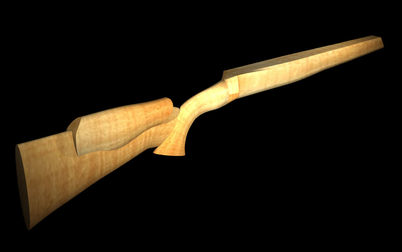
It's my plan someday to build a pair of custom Mauser actioned rifles. A friend of the family got interested in doing this, and we decided to all work together. I'm going to build two and give one to my son. In fact, I'm hoping he'll help out. I haven't gotten far, so the project is still on the Wish List page. However, I did try my hand at designing a gun stock for the rifles in Rhino 3D:
Collet Chuck
Made from Automatic Transmission Planetary Gear Set
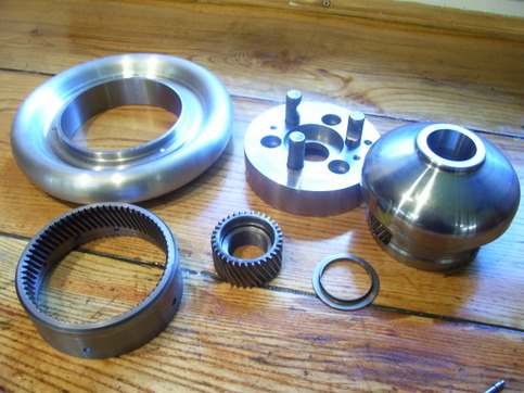
From the category of Amazing Stuff, I present this 5C collet chuck that a fellow from Practical Machinist named "j
king" made. It uses a planetary gearset from a transmission to gear down the handwheel in a compact way and tighten the thread on the collet. The handwheel is nicer than the keyed 5C chuck I've got (and which I still need to make a backplate for!). Other detail notes: there is an O-ring to keep the handwheel from rattling, and there is a sleeve pressed into the small gear. Since the transmission gears are hardened, the sleeve was necessary to allow threading for the 5C collet. It is brazed into place. The workmanship and sheer beauty of it is amazing:
The component parts. Note there is a gear barely visible in the righthand part, and the little gear in the middle is threaded for the 5C collet...

Here is a better view of the gear mounted in the chuck...
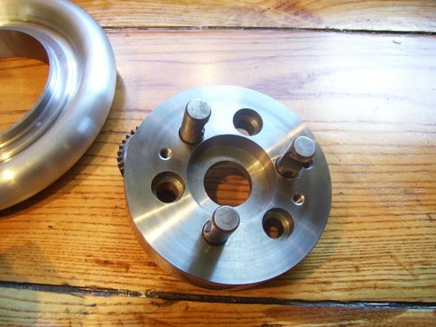
The D1-3 backplate, also a beauty...
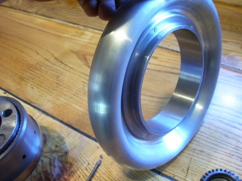
Handwheel looks CNC'd, but was done manually...
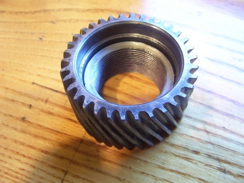
Threaded for the 5C collet...

Thrust bearing inside to keep from over tightening...

Here it is assembled and ready for use...
Looks like he's using that thing on a Monarch 10EE lathe, another really nice piece of work.
I purchased a gearset on eBay and am awaiting a time to get my own chuck made.
Texas Smoker
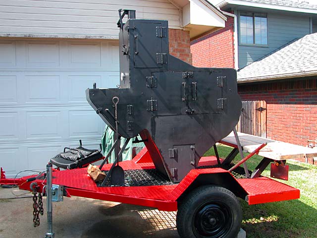
This is more of a big fabrication project than a machining project, but it is metal and it is near and dear to my heart:
Check out my project page for the Texas Smoker...
I do a lot of smoking and currently use a commercial smoker. If you're interested in cooking, visit my recipe site, WineandRecipeParty.com.
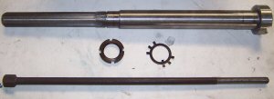
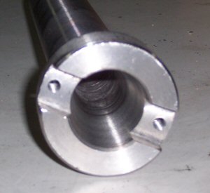
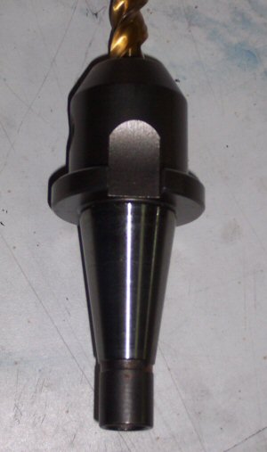
High Speed NMTB
30 Spindle for the IH Mill
As part of Industrial Hobbies going out of business sale, I had the opportunity to purchase a #30 taper spindle that fits the mill for $65. The recommended angular contact bearings to go with the spindle were another $100 from McMaster-Carr.
I like the idea of the #30 taper for a variety of reasons including:
- Greater Rigidity than R8
- Faster tool changes due to better ejection and less fooling around to line up the drive pin of the R8. The #30
taper uses a couple of big dogs to drive the toolholder that are real easy to see and line up compared to the hidden and fairly small drive pin of an R8. - Greater potential to create an automatic toolchanger for the mill. A #30 taper and a powered drawbar can act as a toolchanger under CNC control if you simply provide a tray of tools in fixed positions on the table.
Perhaps the biggest reason, however, was my desire to convert my mill spindle to run at higher speeds using a belt
drive. Out of the box it maxes out at 1600 rpm. With a bigger motor, you can run it to 3200 rpm. That's still pretty slow when you're trying to cut aluminum. My copy of ME Pro wants to see 3900 rpm on a 1/2" end mill with aluminum, and this jumps to 9200 rpm with a 1/8" end mill that I might use for fine profiling. I don't even want to talk about what's need to do engraving!
Given how slowly most of my projects proceed, I decided that buying one of these spindles from IH and building
a whole new belt driven mill head around it was likely to be a better approach than trying to modify the gear head. Taking the latter course would very likely leave me stranded without a working mill for a long time, with much assembly/disassembly back and forthing until I got it right. Building a separate head just requires me to build a box that is rigid and allows me to properly mount the spindle bearings and the motor, with a timing belt from one to the
other. I would dispense with a quill altogether as this head is intended for CNC use and dropping the quill would allow me to make everything that much more rigid and accurate as well as simpler.
At least that's the theory!
Antikythera Mechanism
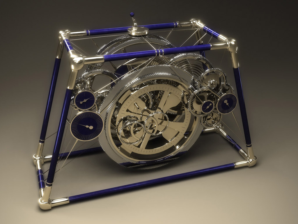
I've always had a great interest in Astronomy, and I read with great interest recent articles about the Antikythera
Mechanism, which was apparently an ancient orrery or simulator of motions of the heavenly bodies. The machine, which was constructed circa 80 BC, could represent the motions of most heavenly bodies known in its time using a clockwork consisting of 37 gears. Such a device seems far more intriguing to me than simply making a clock.
Above is one fairly fanciful 3D representation of a modern equivalent to the Antikythera Mechanism.
Lathe Shaper
Attachment

Cutting keyways is painful if your only approach is racking the cross slide back and forth by hand. It would be awesome to build a shaper attachment that fits a QCTP for doing lightweight keyway cutting under power. Here is
a pneumatic unit one fellow (Evan Williams from HSM board) is designing for the purpose:
And here is his hand powered slotter:


I did order a "left-handed Veeblefetzer" off the web that I think could serve as a component for a shaper attachment:
 The left-handed Veeblefetzer...
I'm thinking I'll build a manual shaper attachment first, and worry about a power unit later.
Here is a clever design for a slotter that just moves the compound on its dovetail:
 The round "faceplate" is being used as a dividing head to allow broaching an internal
gear on a Wankel motor project...
 Dividing head is indexed
via the pin that is on the follower rest mounts...
Related Links:
https://www.lathes.co.uk/adeptshaper/index.html:
They used to make these!
https://www.duwaynesplace.com/hand_shaper_project.html
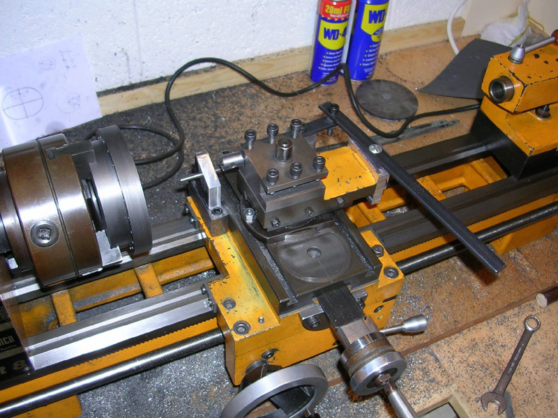
4th CNC Axis
for the Mill
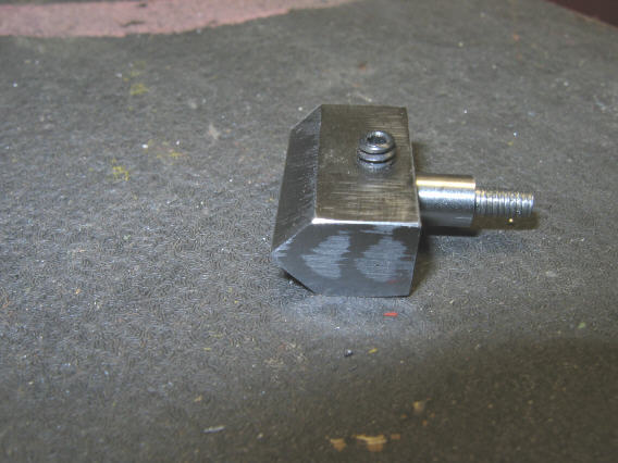
The photo shows the components of a stepper motor conversion of a rotary table. Lots of clever ideas there:The cylinder has a "tophat flange" that catches on a groove cut in the square NEMA plate for the motor. In effect, the motor's flange sandwiches the square flange with the cylinder bringing it all together neatly. The other clever move was to machine the shaft adapter so it can serve as one half of an Oldham-style coupler. This was a really nicely done conversion.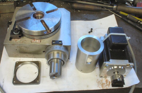
Toolpost Grinder
There have been several times when I've wished for a toolpost grinder to finish a shaft just right and to close tolerances. I debate whether to buy a used Dumore or Themac on eBay or try to fabricate one as a project. Simple ones are really easy to make and just involve lashing a suitable Dremel or hand grinder to the post in some way.
More complex versions involve fabricating a spindle and replicating the style of the commercial TP grinders. I am really tempted to work on a spindle for one. It would be a good warmup should I ever choose to make a more ambitious spindle, perhaps for a lathe or a mill.
Toolpost Grinder Project Page (Just More Ideas and Pictures for Now)!

Router-based TP Grinder: A Bit Heavier Duty!
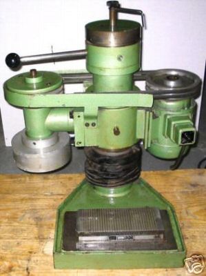
In the fullness of time, I'd like to restore Blanch, my baby Blanchard-style surface grinder to full operating condition.
Tubing Bender and Other Fabrication Tools
Welders and fabricators know how to get down and dirty and git ‘er done, so I’m always interested in what sorts of tooling they’ve dreamed up. One great community there is Pirate 4×4. Whether you’re interested in off-roading or not, there’s a lot of fabrication being done by off-roaders. Here are some samples around tubing benders:
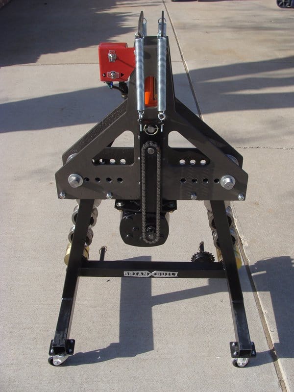
This is a substantially upgraded HF bender.
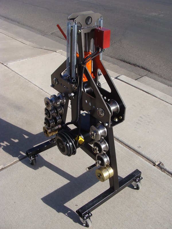
And another shot…
Same HF Bender, different upgrades. This time using an HF pipe threader to provide the power. Quite a few variations on using the pipe threader to power a bender on that thread.
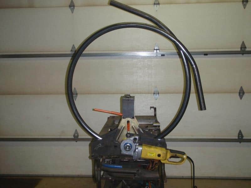
Of course my all-time favorite tubing bender project is a CNC (natch!) Bender from a Cal Poly student who built an NC-controlled hydraulic tubing bender from scratch. He’s a MechE student and it is just the coolest project ever.

Wow! NC-controlled Tubing Bender…
I wish I could say I was adding this one to my project list, but truthfully, it looks too ambitious for me at the moment. Maybe someday when I have more time and experience I will revisit. Meanwhile, I just enjoy reading the thread he’s written.
The lowly drill press is a handy gadget, but mine could use some help. Here is a whole page of ideas for
souping it up.
Be the first to know about updates at CNC Cookbook
Join our newsletter to get updates on what's next at CNC Cookbook.