I've always admired 6-jaw chucks for their mechanical beauty. Many respected machinists, such as those from 5Bears and the Machine Shop Trade Secrets book, prefer them over 3-jaw chucks for fine work. In fact, the latter book rarely shows 3-jaw chucks, focusing instead on 4-jaw and 6-jaw versions. The advantages of a 6-jaw chuck are clear.
With this in mind, I soon found a high-quality 6-jaw chuck on eBay—a 5" Buck Chuck with set-tru capability. I bought it at a significant discount from retail. My next task is to machine a backplate to fit it to my Lathemaster, marking my first precision project.
Follow along while I plan and execute this project.
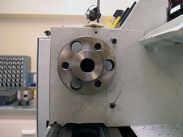
The Spindle Nose...

Drawings
My main concern is that the chuck be accurate on the lathe. It is an expensive chuck, particularly with the set-tru capability, and I want to realize its full potential. With that in mind, the first order of business is to machine the interface with the chuck spindle. If we do that, we can actually mount the adapter to the spindle and carry out the remaining machining operations from there, thus ensuring maximum accuracy (I think).
Getting the spindle interface right is a matter of getting 3 mounting bolts positioned exactly correctly as well as boring the proper hole for the spindle nose. This spindle nose measurements are thus:
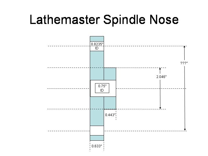
The closest and most important fit is with the spindle nose 2.046" diameter to a corresponding hole in the back plate. The 0.8235" spacer holes are a less tight fit, but we are placing them using a bolt circle, which is a calculated layout. I'll be double and triple checking it to make sure I get that bolt circle right!
On the other side of the adapter plate is the interface for the Buck 6-Jaw chuck. In this case, we have 6 evenly spaced bolt holes for bolts that will hold the adapter plate to the chuck, together with a hole in the chuck that accepts a nose on the adapter. This hole is where the set-tru feature comes into play. Within the hole are 4 Allen head adjustment screws that enable the chuck to be moved radially versus the axis in order to get it exactly aligned to the spindle's axis. Dimensions for the Buck chuck look something like this:
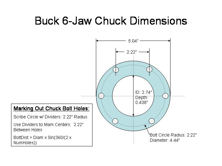
There is some good news here. For example, the spindle nose diameter (2.046") is smaller than the set-tru hole (2.74"). This means that the hole needed for the spindle hole can ride comfortable as a bore inside the nose that mates with the chuck.
Here is a Rhino 3D model I made immediately after I got Rhino. This was after I'd already made the backplate:
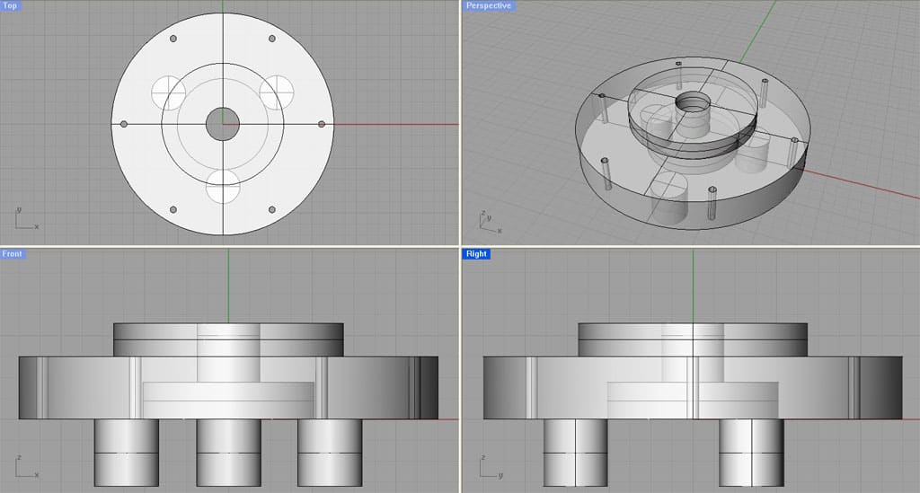
3-View "Ghosted" Solid Model of the Chuck Backplate...
Materials and Tooling
I purchased a couple of cast iron round pieces from www.metalexpress.com. A lot of materials would work, but the cast iron is pretty easy to machine, and is often used in machine parts where a hardened piece isn't neccessary. I bought 2 pieces that were 2" thick by 6" diameter. This is pretty large, but I have another lathe chuck I also need to make a backplate for that is a 6", and they didn't have much between 5" and 6". We'll see how painful it is to rough out so much material. Given the mess involved with machining cast iron, I would be tempted to go mild steel the next time around. A piece of 12L14 would be much easier!
Tooling Used:
Dykem
Combination Square with Center Head
Carbide Scriber
Drill Press
Tap Magic
TiN-Coated Drill Bits
Center Drills
Center Punch
Dividers, Outside Calipers, and Oddleg (Hermaphrodite) Calipers
Dial & Digital Calipers
Several Lathe Tools from Glanze 5/16" Indexable Carbide and 1/4" Brazed Carbide Sets
3 and 4-Jaw Lathe Chucks
Live Center
Telescoping ID Gages
Micrometers
Letter and Number Stamps
Height Gage
Granite Surface Plate
Tailstock Drill Chuck
Tailstock Die Holder
Dichropan T-4 Cold Bluing Solution
Making the Adapter Plate
I'll tell you right now that the way I did this was wrong in several ways. What follows is what I actually did, so you can observe first hand the confused thought processes of a novice. It just goes to show how important it is to really plan the job ahead of time and not just meander around doing what pleases you. At least that's true if you care about proficiency at all. I must say that I still had a heck of a good time with it and learned a lot from my mistakes.
Boring the Off-Center Chuck Mounting Holes:
Being a bit daunted by how to hold my big chuck of cast iron in the lathe, I decided to start out boring the off-center holes on my drill press. Later, discovered this decision was a bad one, but not catastrophically so. The problem is that the cast iron blank I started with turned out not to be flat on the ends. This ensured that the holes drilled were not exactly parallel to the axis, and so they didn't line up quite right. The solution: enlarge then enough to provide clearance and make a mental note. It seems like the right way to begin any project is by squaring the workpiece!
There are 6-holes on a 2.22" radius bolt circle needed for the chuck mounting bolts. To mark out these circles apply Dykem to one side of the cast iron workpiece. This gives you a nice colored surface that will make it easier to see your scribed layout lines.
Next, I marked out the center of the workpiece using my combination square with the centering head. I simply scribed two lines through the center at roughly right angles using my carbide scriber. Using a center punch and a light tap with a ball peen hammer, I made sure there was an accurately positioned center dimple that my divider point could ride in.
Having located the center, I scribed the bolt circle using a pair of dividers. The radius on the dividers was set using my dial calipers. Once I had a bolt circle, I center punched a point on the circle to be the center of one of the 6 chuck mounting bolt holes. I then took the dividers, and set them to the distance between bolt centers. This can be calculated by the following formula:
Bolt Distance = Diameter * Sin( 360/(2 * Number of Bolt Holes))
In order to check my math, I did a dry run around the bolt circle. I set the divider leg in the first center-punched bolt center, put the other leg onto the circle, pivoted the first leg to the next stop on the circle, and so on. Each leg set down is a potential bolt center. If you have all the distances right, you can walk all the way around the circle, touching down once on each bolt center, and wind up exactly back at the original center punched bolt center.
If all is well with your math and measurements, go ahead and do the walk around with the dividers once more, only this time, scribe a little arc across the bolt circle at each stop. The intersection of the arc and the bolt circle becomes the center point for the bolt. Center punch each one of these. Okay, we have now marked out the 6 hole circle for the chuck side of the backplate. Next step was to scribe the circle that will be the OD of the adapter snout that must fit into the set-tru cavity on the Buck chuck.
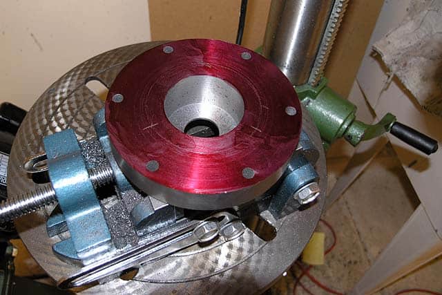
Having completed the layout work on one side, I then carried the cast iron blank over to the drill press, and center drilled each of the center punched dimples, including the center. Having done the center punching, I got out my drill bit set and proceeded to bore a 0.274" ID hole (or thereabouts, I just trial fitted the shaft of the bits into the chuck until I got a good fit) in each of the 6 spots as well as the center. I wanted the center hold to align to when laying out the other side, to ensure everything stays concentric.
Boring the cast iron went pretty quickly. I used Tap Magic as a coolant and lubricant, kept my chip brush handy, and backed the bit out of the bore frequently to clear chips. Eventually 7 holes were bored. As a check, I got out my transfer punches, dropped one into place through the chuck mounting bolt hole and into the adapter hole. I next checked whether the other 5 holes lined up with the chuck using my trusty drill bit. Everything was pretty darned close: I could get 5 of the 6 holes perfectly, with the 6th being not quite spot on. I believe if I increase the ID of all of these holes slightly, life will be good. We don't need perfectly tight holes because we're going to use the set-tru feature of the chuck anyway. I later decided the problem with the hole was that I didn't square the piece before layout and boring.
Turn, Face, and Make A Spigot for the Chuck to Grip:
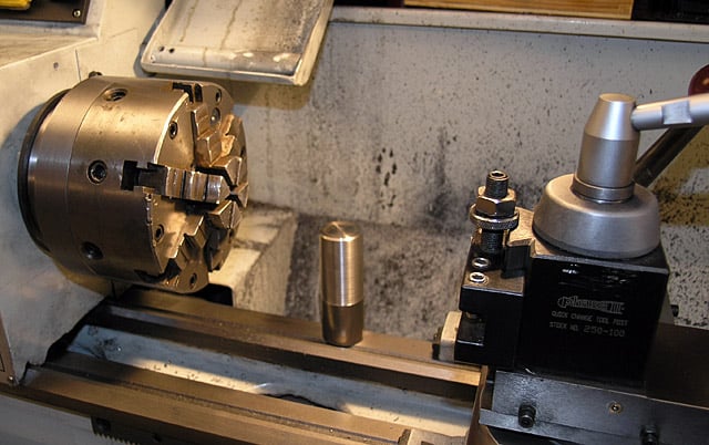
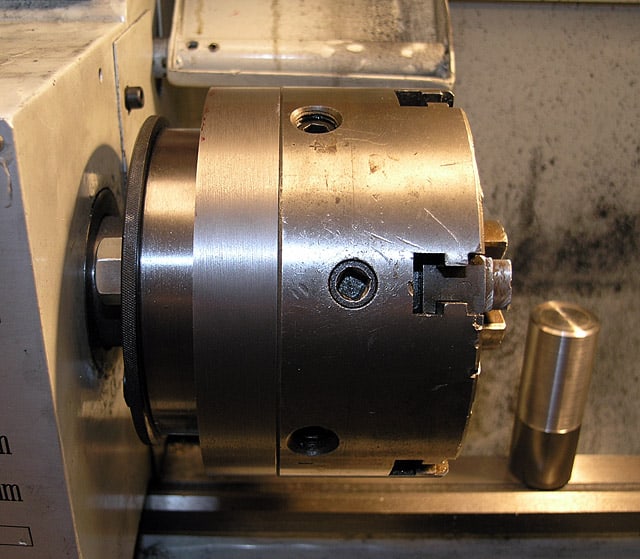
I couldn't procrastinate forever before mounting this thing in the lathe. In fact, I shouldn't have procrastinated at all. This piece was about 6 inches in diameter-way too big for my chucks. I therefore had to improvise another mechanism to hold the cast iron in order to work on it. I opted for Steve Bedair's method of drilling a center hole for a large bolt and then holding the bolt in the lathe. I decided to get a little bit fancy, hoping to increase precision, and finished a shaft to fit fairly snugly, with a threaded hole in the shaft I could use to tighten down a bolt and washer. In the end, I think a plain bolt would have been just as good, but it seemed worth a try at the time. Here's what it looked like with the sleeve held in the chuck:
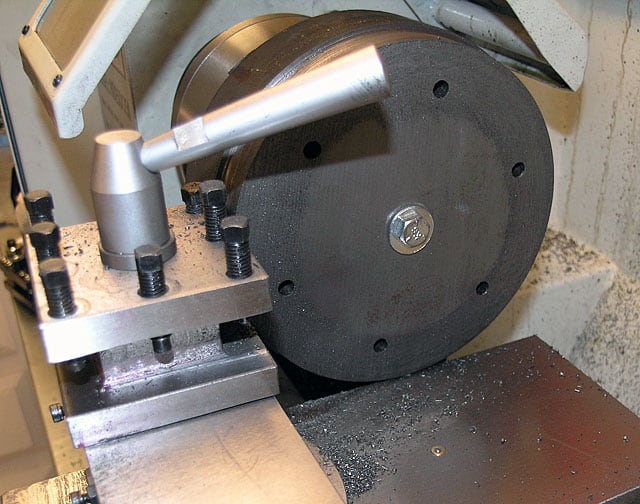
Whoa! Check the clearance, Clarence!
There are a couple of things to note about this picture having to do with clearances. I quickly found out that machining this blank was really at the limits of the lathe's capabilities in many ways. First, the carriage would barely fit under. In fact, I had to stick the tool way out over the edge and turn it down a bit to get there, working a little at a time in several passes to take off about 3/16" before I could just get under. Second, my nifty Quick Change Tool Post absolutely wouldn't clear no matter what I did. The turret post that came with the lathe gives a little better clearance. Don't throw it out when you get your QCTP on! Many, I'm sure, would have made up a plinth toolpost arrangement to deal with this problem. The last problem was chatter. Mounting the cast iron on that sleeve left way too much flex in the system. I wanted to use a much larger bolt, but boring a decent sized hole in my drill press just wasn't working out, so I forged ahead. I don't know how much better a bigger bolt (say 3/4") would have faired, but "It couldn't hoit!"
Even with the chatter, I was able to cut 20 thousandths with each pass. I recently read an article about a guy with a Southbend who was trying to do something similar and claimed it was absolutely impossible to cut more than 3 thousandths on each pass. Not too bad when an Asian lathe surpasses the might Southbend! With that said, I have to assume the guy was either doing something wrong or his Southbend was worn out and full of slop. Probably the latter. I stick by my decision that I was better off with new Asian machines rather than trying to rebuild old classics.
You can see all the nasty gritty dust and graphite cast iron throws off. It does, however, cut pretty easily. When I get done with this piece I'm going over the lathe again just like when I unpacked it to make sure I get all that stuff out of the innards.
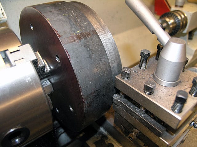
Turning down the spigot...
In this shot, you can see the other side, as well as the spigot I'm starting to produce. Note the nasty chatter marks on the turned piece! It took me quite a while to turn this down far enough that I could take it off the sleeve, flip it around, and clamp it in the chuck. It was worth the wait:
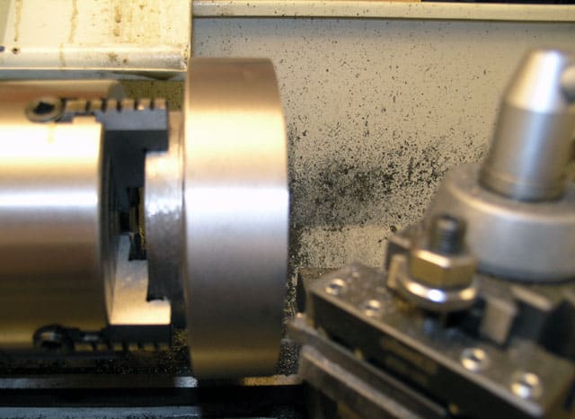
Nasty chatter marks on left, smooth finish on right...
You can still see those horrendous chatter marks on the spigot, but check the turned surface for a comparison. With the piece flipped around and properly mounted in the 4-jaw, life suddenly got a lot better. The chatter went away, the finish improved dramatically, and I could crank up the spindle speed to really let my carbide tools sing. At this stage, I still have a lot of material to take off both turning and facing, but it's a whole lot more comfortable doing it.
Make a Spindle Plug Gage:
This just makes it easier to accurately measure the hole you will bore for the spindle nose. It's very quick to turn such a gage to size, and it will be useful for other projects. I turned mine with a shoulder in case I want to later produce a full spindle replica (useful when mounting your chucks to other tooling). I also used my number and stamp set to mark it's dimensions and purpose on the back. This was easy to do, using masking tape as a baseline to line up the text, and made the whole thing look a bit more professional. I'll still be able to read that stamped text long after tape or ink would have been worn off and lost.
This gage should be the first thing you make, BTW, under ideal circumstances. I stopped in the middle, before boring the spindle hole.
Spindle Facing Side:
Once having turned and faced to reasonable dimensions, I bored the 2.046" ID spindle nose hole to a depth 1.25". This is probably more than I need depth-wise, but I'd rather have too much than too little. Make a last facing cut on the spindle spacing side to achieve a fine finish that's nice and flat.
Chuck Facing Side:
Now that the cast iron blank is of more reasonable size, i.e. 5" OD, I was able to flip it around so the chuck side was exposed and place it in my 4-jaw.
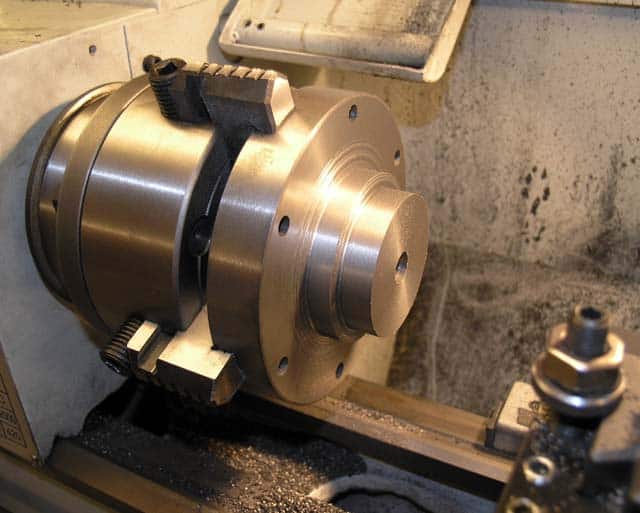
I'll turn down the nose to get to the right length rather than facing it down...
Turn the shoulder that will fit inside the chuck to 2.74" OD by 0.5" deep. Face the part that goes inside the chuck. When looking to get to the proper depth for the spigot, as well as the overall length of the backplate, I had to remove quite a lot of material. I remembered the adage learned from Machine Shop Trade Secrets: remove that material by turning, not facing, it goes much faster. He was right too! This is especially so for a cheap Asian lathe that lacks a power cross feed. When facing you can use the leadscrew feed. The downside is you build up an irregular shoulder that will have to be properly faced, so be sure to take that into account on your planning for how much material to remove.
Face the shoulder that goes against the chuck. I did this facing operation before my final turning on the spigot that goes into the chuck. The latter I undercut a little deeper than the shoulder so it would all fit cleanly and squarely.
Trial fit the chuck over the back plate nose before removing the back plate from the chuck.
Making the 3 spacers:
Before beginning to make these three spacers, I realized I was going to need a tailstock die holder for threading. The threads really need to be lined up straight as these pieces need to fit true to ensure proper alignment. So, you may want to take a brief detour over to the tailstock die holder page if you don't already have one of your own. It's an easy project and very handy once you are done.
Place some round steel stock at least 0.8" or greater in diameter in the 3-jaw chuck. I used an 8" length. I'm cutting a pretty long length, so I'll turn with the live center.
Center drill and install live center. I wound up using my cut-off tool to create the edges of the spacer-it made them nice and flat as well as providing the necessary clearance for me to go in and turn down the threaded areas to the proper OD.
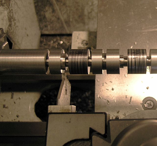
Using the cut-off tool to groove next to the spacer bodies (colored in Black with a Sharpie)...
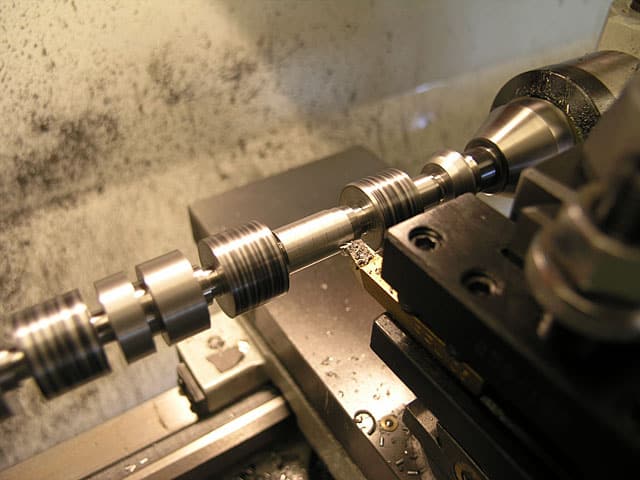
Now I'm turning down the threaded areas to proper OD. I used a 1/4" carbide insert tool for this-there wasn't room for my normal Glanze 5/16" indexable tools! I also had to cut two passes with the cut-off tool to gain enough room to work in. Finally, that cut-off groove also provided a relief groove inboard of the threads.
Once the proper OD's are turned on the shaft, you can remove it from the lathe and use the vertical bandsaw to cut apart the pieces. I made four even though I only needed three. It only takes a little longer and you have a spare if things go wrong.
Spacer blanks cut apart with the vertical bandsaw. Note the clearance grooves where the threading can stop...
Now I put each one back in the lathe, fired up my new tailstock die holder, and cut the threads. Along the way I also used a well-chalked file to finely bevel any sharp edges before threading.
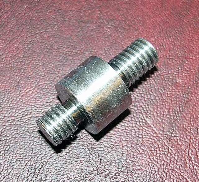
It's a bit groady looking with this much magnification. The whole thing is about 1" long.
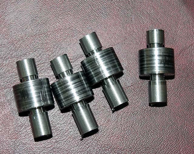
As a last fit of ornamentation, I decided to try out a little cold bluing solution (Brownell's Dicropan T-4 and Oxpho-Blue Creme were both tried) to put a finish on the little buggers. The original spacers that came with the lathe have some sort of a black oxide finish on them too. I have to say, I like the effect. People complain that cold bluing looks lousy on guns, but for parts it beats an unfinished state and is really easy to do!
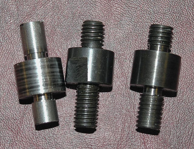
Blank, original that came with the lathe, and my freshly cold blued part. I like my finish better, although the threads look lousy!
On the originals there is a 5/8" flat milled for a wrench, but they seem to work fine finger tight, so I did not provide the wrench flats. If it gets too annoying I may Loctite the spacers in. In fact, I am tempted to do that on the originals too.
Final Assembly: We're almost done!
Bolt circle for spacers marked out with Dykem...
Mark out the bolt circle for the spacers. Since I had already bored the spindle nose hole, I my oddleg (hermaphrodite) calipers to mark out the circle. I then eyeballed the right between hole spacing on a finished backplate using a pair of dividers. Walk the dividers around the bolt circle on the new backplate. You'll see whether they are too wide or too narrow-dividers that adjust with a threaded fitting are handy here. Remember that the circle magnifies the error since you go around once for each bolt. When you get to where you can walk the dividers all the way around the circle and end up exactly where you started, you have the right distance and can now scribe the cross points to drill. There are also math formulas to calculate the distance, but this was quick and easy for me.
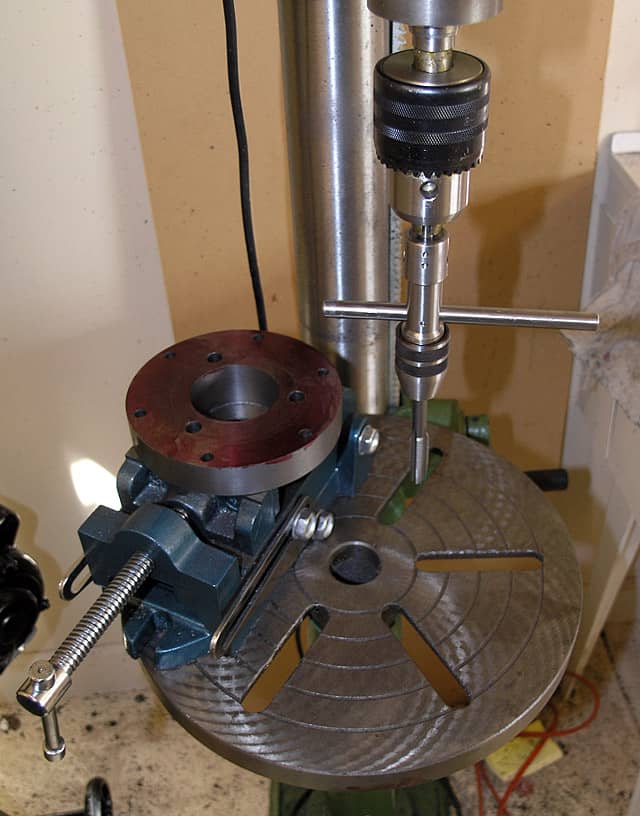
Preparing to Tap with Piloted Tap Wrench (Enco purchase)...
Drill the holes for the threaded spacers. Tap them. Assemble the chuck and backplate and trial fit to the spindle. The last step for me was to counterbore the 6 chuck bolt holes so that the bolt heads and nuts would be recessed.
The chuck installed together with the first trial piece turned. Runout adjust easily to 0.001" with Set-Tru!
This is an experienced chuck-some dings!
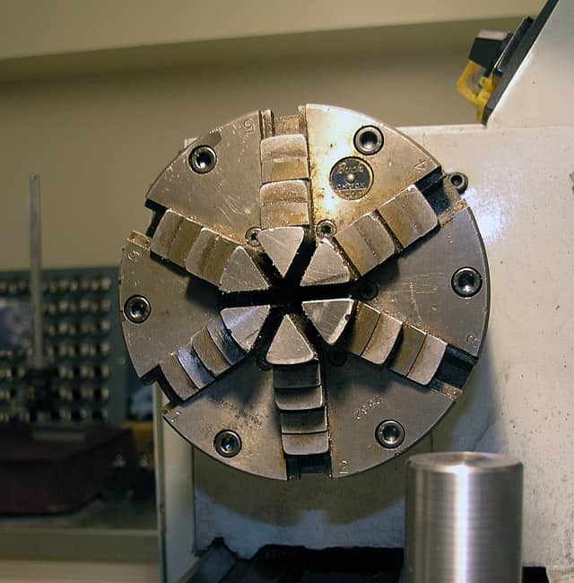
It is a beauty though, no?
When all was said and done, was it worth it? I have to say it was a worthwhile project for me. I got the chuck on eBay for $240, which is much less than the new cost for the chuck. In addition, it was good experience to make the backplate. I have to say that the feel of this chuck is far superior to the Asian chucks that came with the machine. The key is silky smooth, with virtually no trace of backlash.
Problems I Encountered, Things I Learned...
- My method of using a bolt to hold the initial blank until I could machine a spigot a chuck could hold worked very poorly. There was tremendous chatter involved. I've seen someone else center drill the bolt and bring a live center in to the equation. That, and a much large bolt seem like must haves for the next go-round with this. OTOH, I got through it without harming the lathe or myself so maybe I shouldn't sweat it!
- It's hard to lay out precision bolt circles by hand. The circle for the 3 spacers was off on 1 spacer by 5 thousandths. It was that much closer to center than the other 2 holes. I fixed it by turning down that spacer to a slightly smaller diameter. In future I'd like to find a way to lay these out more precisely.
- I drilled my 6 holes for the chuck without first facing the ends of the cast iron blank. Those ends were not square to the sides so neither were the holes. I made them slightly oversized and it all worked out fine. They're just clearance holes. I would have been in a world of hurt had precision mattered here.
- Cast iron is pretty tough to machine! I would be tempted to use 12L14 the next time. Looks like I will get the chance as I need to make backplates for 2 more chucks.
- I am suspicious of the accuracy of my cheap Asian drill press. Eventually, I will own a mill which will be much more accurate. Also, I drilled using a big vise, but a clamping kit would have been helpful as well.
- When I first inserted the spacers in their holes, it looked like the threads were cocked. This was disappointing since I had used a piloted tap wrench to get them straight in the first place. It turned out that the threaded inserts were just too long. I used a tapered tap to thread the holes and the tapered end needs a lot of hole depth to start making threads. I solved the problem by facing some of the threads off on the lathe, doing so with a nut in place so that removing the nut would straighten out any damage I did to the threads. A better answer would be to use a bottoming tap and thread the hole all the way to the bottom.
- Initially, one of the three nuts would not go through the spindle hole-I had to remove the nut mount the chuck, and put the nut on from the other side. I had assumed this was due to some of the other precision problems, but this turned out not to be the case. I tried to put a wrench on it, and while this nut was identical to the others thread-wise, it required a significantly larger nut! My brother-in-law says that my mistake was in assume to quickly I was the one with the precision problem rather than the nut factory. Go figure!
Be the first to know about updates at CNC Cookbook
Join our newsletter to get updates on what's next at CNC Cookbook.