The Quick Reference page of G-Wizard Machinist's Calculator includes a variety of helpful reference materials:
- Drill Index Chart
- Fastener Reference
- Weights and Volumes Calculator
- Thermal Expansion Calculator
- Electrical Calculator
- G and M-Code References for CNC
- Hardness Conversion Chart
- Rigidity Calculator
- Chatter Calculator
- GD&T Calculator
- Notebook
The other tab that's full of calculators and references is the Geometry Tab. Go there for everything from a Press Fit Calculator to trig and shop math calculators.
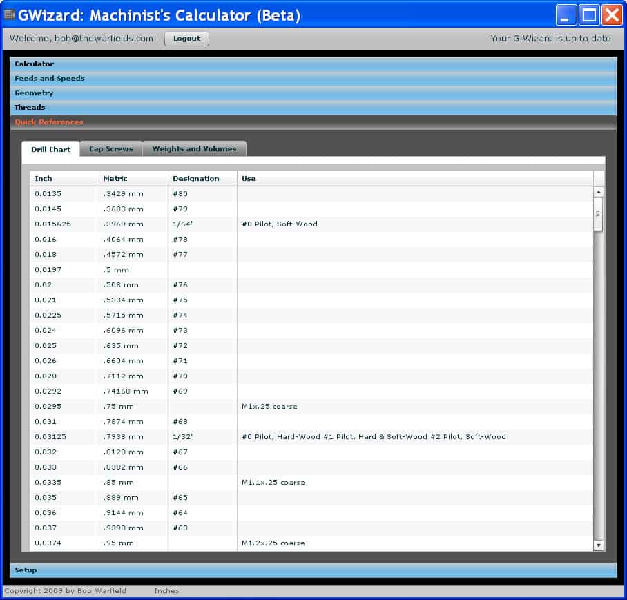
The Drill Chart is a complete Drill Index-style listing of twist drills that includes their diameter in Imperial and Metric units, their name (designation), and uses for that drill.
Cap Screws
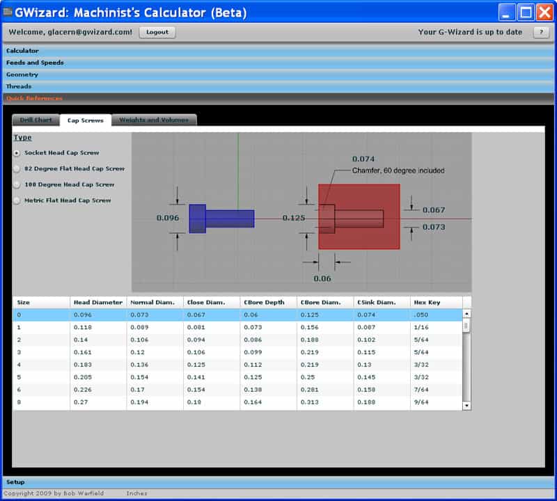
The Cap Screw page includes dimensions for common sizes of Socket and Flat Head Head Cap Screws, the holes they fit into, as well as what size hex key should be used with each size:
Weights and Volumes
Visit our article on calculating metal weights and volumes for details on the Weights and Volumes Calculator.
Thermal Expansion Calculator
[ See our detailed article on G-Wizard's Thermal Expansion Calculator ]
G and M-Codes
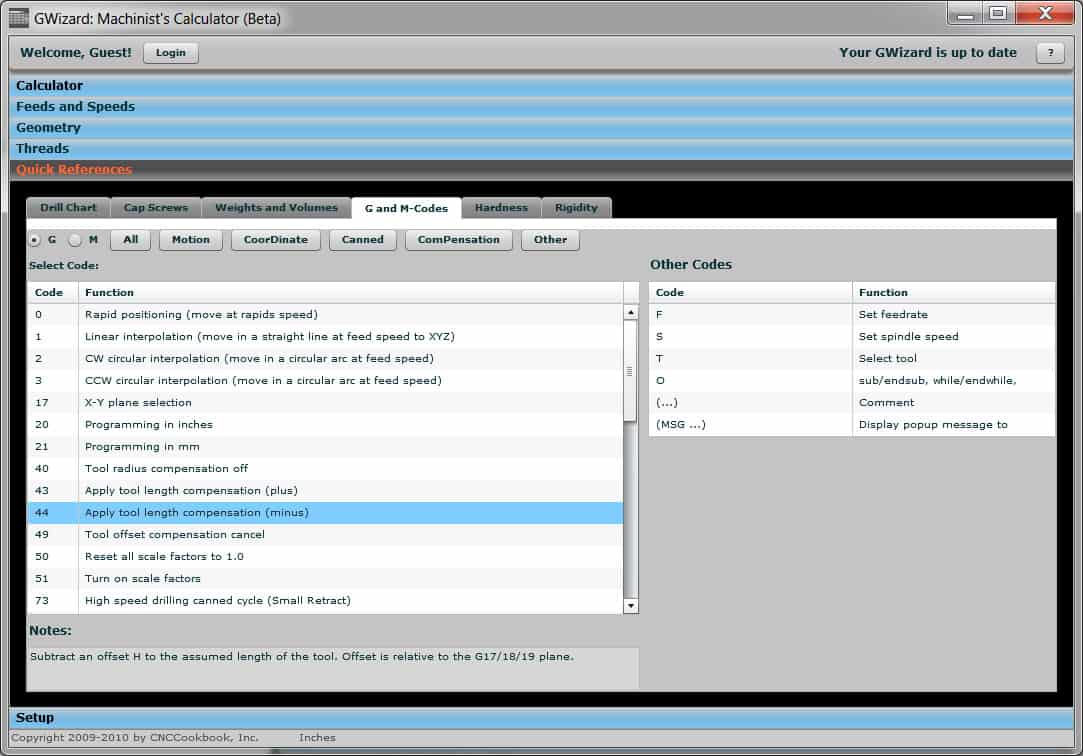
The G and M-Code reference is a handy way to look up the codes. To use it:
- Select whether you want G- or M-Codes on the top line.
- If you select G-Codes, an additional set of selection buttons pops up like the ones shown in the screen shot. You can use these to narrow the list, for example to show just "Motion" related G-Codes like G0, G01, and G02/03. The capitalized letter tells you the keyboard shortcut on the buttons.
- As you select codes, there are notes associated with them that tell you a bit more. The screen shot shows how the "H" parameter is used with G44 for Tool Length Compensation, for example.
G and M codes are covered on the left, while on the right is a brief list of the other kinds of codes you can put in a CNC program.
Hardness
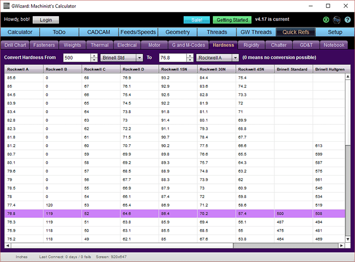
The Hardness tab provides a quick reference hardness conversion chart and calculator for converting between the different units of hardness.
Rigidity Calculator
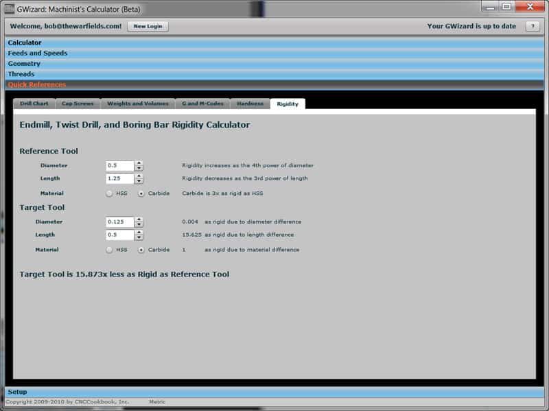
A 1/8" endmill versus a 1/2" endmill...
The calculator breaks down how much each component, cutter diameter, cutter length, and cutter material, affects the overall rigidity. The length is measured from where the tool holder or collet ends to the deepest point where cutting occurs. So in this example, we're saying 1.25" down from the tool holder on the 1/2" endmil and 1/2" down on the 1/8" endmill. The result is that the 1/8" endmill is about 1/16 as rigid as the 1/2".
Consider some other scenarios we can analyze with the calculator:
- A 1/2" endmill at 1" depth is 1/2 as rigid as the one cutting 11/4" deep. Be careful with deep cuts and choke up on the tool as much as you can in the holder.
- A 1/4" endmill at 1" depth is almost 1/16 as rigid as the 1/2" endmill at 1" deep. Use the largest diameter endmill that fits your internal radii.
- A 5/8" endmill at 1" depth is 2.4 times more rigid than a 1/2" at 1" depth. I have a little 5/8" Iscar Helimill indexable cutter. Even though it adds a mere 1/8" in diameter, it is more than twice as rigid. That's why I like to rough with it.
For turners, you can get a sense of the rigidity of different boring bars from the Calculator as well. It's no wonder that using the biggest carbide bar that fits the hole makes such a difference!
If you're having a problem with deflection, try this calculator. I'd look at increasing rigidity 2-4x and seeing if the deflection problem doesn't go away or isn't greatly reduced. If it is still an issue, bump up another 2-4x in rigidity until you get rid of it.
Have you gone through Setup of your G-Wizard Calculator yet?
Be the first to know about updates at CNC Cookbook
Join our newsletter to get updates on what's next at CNC Cookbook.
