Introduction
Structural Steel is available in a variety of standard sizes. You'll find the dimensions for those sizes in our handy tables below, grouped by structural shape. In addition, there is helpful information on the applicable standards and other basics.
Structural Steel is generally referred to by its profile (for example "I-Beams") and its size. Sizes are determined by standards which are described in the sections for each shape below.
One goal of Structural Steel that goes to determining the shape is that it have high second moments of area, which make them very stiff in respect to their cross-sectional area. This makes them strong relative to the amount of material and weight that must be used in their construction.
![]()
Common Structural Steel Shapes By William Perry of Mercury Business Development - https://commons.wikimedia.org/w/index.php?curid=5326461...
If you want to learn more about the properties of the different types of steel used in Structural Steel, check out our handy article on types of metals.
Free Steel Size and Weight Calculator
All the data you're seeking on Standard Steel Sizes is available below in tabular form, but why use tables when our free calculator has all the same information and will also help you calculate weight, volume, and costs for job quoting?
Our Steel Beam & Structural Shape Calculator does it all right in your browser—no signup and nothing to download. Pick a shape (Wide-Flange or American-Standard I-beams, channel, angle, or HSS tubing), choose a standard size, and enter a length to get the weight, volume, and material cost instantly. You can toggle between imperial and metric units and change the material to estimate weights for aluminum, stainless, and more.
Grab a steel beam price list from your favorite supplier and you can figure your raw material costs too!
Steel I-Beam Sizes (Steel Beam Dimensions and Weights)
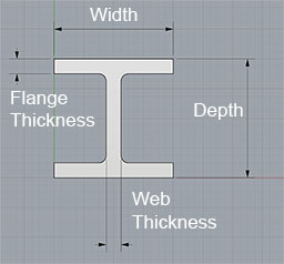
I-Beams are also known as H-Beams, W-Beams (for "wide flange"), Universal Beams (UB), Rolled Steel Joists (RSJ) or Double-T. I-Beams have an I, or if you rotate it, an H-shaped cross-section. The horizontal elements of the "I" are called "flanges", while the vertical elements are the "web." I-Beams are one of several standard structural shapes for steel, and they are commonly used in construction and civil engineering projects.
The shape of the I-Beam provides versatile strength with a minimum of weight. The web resists shear forces while the flanges resist the bending moment experienced by the beam. Thus I-Beams are very efficient for carrying bending and shear loads in the plane of the web. The weakness of the shape is that it doesn't resist torsional forces nor does it have much capacity in the transverse direction. If strengths in those areas are needed, hollow structural sections (HSS) are preferred.
Steel I-Beams are typically produced by a rolling process that was invented in 1849 by Alphonse Halbou in France. The use of rolled I-Beams was common into the mid-20th century. Today, fabricated I-Beams, which are produced by welding together the flanges and web are also common.
US Standards
In the US, the Wide Flange (W-Beams) are the most common. These beams have flanges which are almost parallel. Relevant standards with yield strengths are:
- ASTM A992: 50,000 - 65,000 psi (340-450 MPa)
- A588: Similar to A572
- A572: 42,000 - 60,000 psi (290 - 410 MPa), but 50,000 psi (340 MPa) is the most common.
- A36: 36,000 psi (250 MPa)
A992 has generally replaced the older A572 and A36 standards.
The American Institute of Steel Construction (AISC) publishes the Steel Construction Manual for designing structures of various shapes. It documents the common approaches, Allowable Stress Design (ASD) and Load and Resistance Factor Design (LRFD), (starting with 13th ed.) to create such designs.
Euronorms
- EN 10024: Hot rolled taper flange I sections
- EN 10034: Structural steel I and H sections
- EN 10162: Cold rolled steel sections
Other Standards
- DIN 1025-5
- ASTM A6, American Standard Beams
- BS 4-1
- IS 808 - Dimensions hot rolled steel beam, column, channel and angle sections
- AS/NZS 3679.1 - Australia and New Zealand standard
Steel I-Beam Sizes (Wide Flange)
| Name | Depth (in) | Width (in) | Web Thickness (in) | Flange Thickness (in) | Sectional Area (in²) | Weight (lb/ft) |
|---|---|---|---|---|---|---|
| W 27 x 178 | 27.8 | 14.09 | 0.725 | 1.19 | 52.3 | 178 |
| W 27 x 161 | 27.6 | 14.02 | 0.66 | 1.08 | 47.4 | 161 |
| W 27 x 146 | 27.4 | 14 | 0.605 | 0.975 | 42.9 | 146 |
| W 27 x 114 | 27.3 | 10.07 | 0.57 | 0.93 | 33.5 | 114 |
| W 27 x 102 | 27.1 | 10.02 | 0.515 | 0.83 | 30 | 102 |
| W 27 x 94 | 26.9 | 10 | 0.49 | 0.745 | 27.7 | 94 |
| W 27 x 84 | 26.7 | 9.96 | 0.46 | 0.64 | 24.8 | 84 |
| W 24 x 162 | 25 | 13 | 0.705 | 1.22 | 47.7 | 162 |
| W 24 x 146 | 24.7 | 12.9 | 0.65 | 1.09 | 43 | 146 |
| W 24 x 131 | 24.5 | 12.9 | 0.605 | 0.96 | 38.5 | 131 |
| W 24 x 117 | 24.3 | 12.8 | 0.55 | 0.85 | 34.4 | 117 |
| W 24 x 104 | 24.1 | 12.75 | 0.5 | 0.75 | 30.6 | 104 |
| W 24 x 94 | 24.1 | 9.07 | 0.515 | 0.875 | 27.7 | 94 |
| W 24 x 84 | 24.1 | 9.02 | 0.47 | 0.77 | 24.7 | 84 |
| W 24 x 76 | 23.9 | 9 | 0.44 | 0.68 | 22.4 | 76 |
| W 24 x 68 | 23.7 | 8.97 | 0.415 | 0.585 | 20.1 | 68 |
| W 24 x 62 | 23.7 | 7.04 | 0.43 | 0.59 | 18.2 | 62 |
| W 24 x 55 | 23.6 | 7.01 | 0.395 | 0.505 | 16.2 | 55 |
| W 21 x 147 | 22.1 | 12.51 | 0.72 | 1.15 | 43.2 | 147 |
| W 21 x 132 | 21.8 | 12.44 | 0.65 | 1.035 | 38.8 | 132 |
| W 21 x 122 | 21.7 | 12.39 | 0.6 | 0.96 | 35.9 | 122 |
| W 21 x 111 | 21.5 | 12.34 | 0.55 | 0.875 | 32.7 | 111 |
| W 21 x 101 | 21.4 | 12.29 | 0.5 | 0.8 | 29.8 | 101 |
| W 21 x 93 | 21.6 | 8.42 | 0.58 | 0.93 | 27.3 | 93 |
| W 21 x 83 | 21.4 | 8.36 | 0.515 | 0.835 | 24.3 | 83 |
| W 21 x 73 | 21.2 | 8.3 | 0.455 | 0.74 | 21.5 | 73 |
| W 21 x 68 | 21.1 | 8.27 | 0.43 | 0.685 | 20 | 68 |
| W 21 x 62 | 21 | 8.24 | 0.4 | 0.615 | 18.3 | 62 |
| W 21 x 57 | 21.1 | 6.56 | 0.405 | 0.65 | 16.7 | 57 |
| W 21 x 50 | 20.8 | 6.53 | 0.38 | 0.535 | 14.7 | 50 |
| W 21 x 44 | 20.7 | 6.5 | 0.35 | 0.45 | 13 | 44 |
| W 18 x 119 | 19 | 11.27 | 0.655 | 1.06 | 35.1 | 119 |
| W 18 x 106 | 18.7 | 11.2 | 0.59 | 0.94 | 31.1 | 106 |
| W 18 x 97 | 18.6 | 11.15 | 0.535 | 0.87 | 28.5 | 97 |
| W 18 x 86 | 18.4 | 11.09 | 0.48 | 0.77 | 25.3 | 86 |
| W 18 x 76 | 18.2 | 11.04 | 0.425 | 0.68 | 22.3 | 76 |
| W 18 x 71 | 18.5 | 7.64 | 0.495 | 0.81 | 20.8 | 71 |
| W 18 x 65 | 18.4 | 7.59 | 0.45 | 0.75 | 19.1 | 65 |
| W 18 x 60 | 18.2 | 7.56 | 0.415 | 0.695 | 17.6 | 60 |
| W 18 x 55 | 18.1 | 7.53 | 0.39 | 0.63 | 16.2 | 55 |
| W 18 x 50 | 18 | 7.5 | 0.355 | 0.57 | 14.7 | 50 |
| W 18 x 46 | 18.1 | 6.06 | 0.36 | 0.605 | 13.5 | 46 |
| W 18 x 40 | 17.9 | 6.02 | 0.315 | 0.525 | 11.8 | 40 |
| W 18 x 35 | 17.7 | 6 | 0.3 | 0.425 | 10.3 | 35 |
| W 16 x 100 | 16.97 | 10.425 | 0.585 | 0.985 | 29.4 | 100 |
| W 16 x 89 | 16.75 | 10.365 | 0.525 | 0.875 | 26.2 | 89 |
| W 16 x 77 | 16.52 | 10.295 | 0.455 | 0.76 | 22.6 | 77 |
| W 16 x 67 | 16.33 | 10.235 | 0.395 | 0.665 | 19.7 | 67 |
| W 16 x 57 | 16.43 | 7.12 | 0.43 | 0.715 | 16.8 | 57 |
| W 16 x 50 | 16.26 | 7.07 | 0.38 | 0.63 | 14.7 | 50 |
| W 16 x 45 | 16.13 | 7.035 | 0.345 | 0.565 | 13.3 | 45 |
| W 16 x 40 | 16.01 | 6.995 | 0.305 | 0.505 | 11.8 | 40 |
| W 16 x 36 | 15.86 | 6.985 | 0.295 | 0.43 | 10.6 | 36 |
| W 16 x 31 | 15.88 | 5.525 | 0.275 | 0.44 | 9.12 | 31 |
| W 16 x 26 | 15.69 | 5.5 | 0.25 | 0.345 | 7.68 | 26 |
| W 14 x 132 | 14.66 | 14.725 | 0.645 | 1.03 | 38.8 | 132 |
| W 14 x 120 | 14.48 | 14.67 | 0.59 | 0.94 | 35.3 | 120 |
| W 14 x 109 | 14.32 | 14.605 | 0.525 | 0.86 | 32 | 109 |
| W 14 x 99 | 14.16 | 14.565 | 0.485 | 0.78 | 29.1 | 99 |
| W 14 x 90 | 14.02 | 14.52 | 0.44 | 0.71 | 26.5 | 90 |
| W 14 x 82 | 14.31 | 10.13 | 0.51 | 0.855 | 24.1 | 82 |
| W 14 x 74 | 14.17 | 10.07 | 0.45 | 0.785 | 21.8 | 74 |
| W 14 x 68 | 14.04 | 10.035 | 0.415 | 0.72 | 20 | 68 |
| W 14 x 61 | 13.89 | 9.995 | 0.375 | 0.645 | 17.9 | 61 |
| W 14 x 53 | 13.92 | 8.06 | 0.37 | 0.66 | 15.6 | 53 |
| W 14 x 48 | 13.79 | 8.03 | 0.34 | 0.595 | 14.1 | 48 |
| W 14 x 43 | 13.66 | 7.995 | 0.305 | 0.53 | 12.6 | 43 |
| W 14 x 38 | 14.1 | 6.77 | 0.31 | 0.515 | 11.2 | 38 |
| W 14 x 34 | 13.98 | 6.745 | 0.285 | 0.455 | 10 | 34 |
| W 14 x 30 | 13.84 | 6.73 | 0.27 | 0.385 | 8.85 | 30 |
| W 14 x 26 | 13.91 | 5.025 | 0.255 | 0.42 | 7.69 | 26 |
| W 14 x 22 | 13.74 | 5 | 0.23 | 0.335 | 6.49 | 22 |
| W 12 x 136 | 13.41 | 12.4 | 0.79 | 1.25 | 39.9 | 136 |
| W 12 x 120 | 13.12 | 12.32 | 0.71 | 1.105 | 35.3 | 120 |
| W 12 x 106 | 12.89 | 12.22 | 0.61 | 0.99 | 31.2 | 106 |
| W 12 x 96 | 12.71 | 12.16 | 0.55 | 0.9 | 28.2 | 96 |
| W 12 x 87 | 12.53 | 12.125 | 0.515 | 0.81 | 25.6 | 87 |
| W 12 x 79 | 12.38 | 12.08 | 0.47 | 0.735 | 23.2 | 79 |
| W 12 x 72 | 12.25 | 12.04 | 0.43 | 0.67 | 21.1 | 72 |
| W 12 x 65 | 12.12 | 12 | 0.39 | 0.605 | 19.1 | 65 |
| W 12 x 58 | 12.19 | 10.01 | 0.36 | 0.64 | 17 | 58 |
| W 12 x 53 | 12.06 | 9.995 | 0.345 | 0.575 | 15.6 | 53 |
| W 12 x 50 | 12.19 | 8.08 | 0.37 | 0.64 | 14.7 | 50 |
| W 12 x 45 | 12.06 | 8.045 | 0.335 | 0.575 | 13.2 | 45 |
| W 12 x 40 | 11.94 | 8.005 | 0.295 | 0.515 | 11.8 | 40 |
| W 12 x 35 | 12.5 | 6.56 | 0.3 | 0.52 | 10.3 | 35 |
| W 12 x 30 | 12.34 | 6.52 | 0.26 | 0.44 | 8.8 | 30 |
| W 12 x 26 | 12.22 | 6.49 | 0.23 | 0.38 | 7.7 | 26 |
| W 12 x 22 | 12.31 | 4.03 | 0.26 | 0.425 | 6.5 | 22 |
| W 12 x 19 | 12.16 | 4.005 | 0.235 | 0.35 | 5.6 | 19 |
| W 12 x 16 | 11.99 | 3.99 | 0.22 | 0.265 | 4.7 | 16 |
| W 12 x 14 | 11.91 | 3.97 | 0.2 | 0.225 | 4.2 | 14 |
| W 10 x 112 | 11.36 | 10.415 | 0.755 | 1.25 | 32.9 | 112 |
| W 10 x 100 | 11.1 | 10.34 | 0.68 | 1.112 | 29.4 | 100 |
| W 10 x 88 | 10.84 | 10.265 | 0.605 | 0.99 | 25.9 | 88 |
| W 10 x 77 | 10.6 | 10.19 | 0.53 | 0.87 | 22.6 | 77 |
| W 10 x 68 | 10.4 | 10.13 | 0.47 | 0.77 | 20 | 68 |
| W 10 x 60 | 10.22 | 10.08 | 0.42 | 0.68 | 17.6 | 60 |
| W 10 x 54 | 10.09 | 10.03 | 0.37 | 0.615 | 15.8 | 54 |
| W 10 x 49 | 9.98 | 10 | 0.34 | 0.56 | 14.4 | 49 |
| W 10 x 45 | 10.1 | 8.02 | 0.35 | 0.62 | 13.3 | 45 |
| W 10 x 39 | 9.92 | 7.985 | 0.315 | 0.53 | 11.5 | 39 |
| W 10 x 33 | 9.73 | 7.96 | 0.29 | 0.435 | 9.71 | 33 |
| W 10 x 30 | 10.47 | 5.81 | 0.3 | 0.51 | 8.84 | 30 |
| W 10 x 26 | 10.33 | 5.77 | 0.26 | 0.44 | 7.6 | 26 |
| W 10 x 22 | 10.17 | 5.75 | 0.24 | 0.36 | 6.5 | 22 |
| W 10 x 19 | 10.24 | 4.02 | 0.25 | 0.395 | 5.6 | 19 |
| W 10 x 17 | 10.11 | 4.01 | 0.24 | 0.33 | 5 | 17 |
| W 10 x 15 | 9.99 | 4 | 0.23 | 0.27 | 4.4 | 15 |
| W 10 x 12 | 9.87 | 3.96 | 0.19 | 0.21 | 3.5 | 12 |
| W 8 x 67 | 9 | 8.28 | 0.57 | 0.935 | 19.7 | 67 |
| W 8 x 58 | 8.75 | 8.22 | 0.51 | 0.81 | 17.1 | 58 |
| W 8 x 48 | 8.5 | 8.11 | 0.4 | 0.685 | 14.1 | 48 |
| W 8 x 40 | 8.25 | 8.07 | 0.36 | 0.56 | 11.7 | 40 |
| W 8 x 35 | 8.12 | 8.02 | 0.31 | 0.495 | 10.3 | 35 |
| W 8 x 31 | 8 | 7.995 | 0.285 | 0.435 | 9.1 | 31 |
| W 8 x 28 | 8.06 | 6.535 | 0.285 | 0.465 | 8.3 | 28 |
| W 8 x 24 | 7.93 | 6.495 | 0.245 | 0.4 | 7.1 | 24 |
| W 8 x 21 | 8.28 | 5.27 | 0.25 | 0.4 | 6.2 | 21 |
| W 8 x 18 | 8.14 | 5.25 | 0.23 | 0.33 | 5.3 | 18 |
| W 8 x 15 | 8.11 | 4.015 | 0.245 | 0.315 | 4.4 | 15 |
| W 8 x 13 | 7.99 | 4 | 0.23 | 0.255 | 3.8 | 13 |
| W 8 x 10 | 7.89 | 3.94 | 0.17 | 0.205 | 2.9 | 10 |
| W 6 x 25 | 6.38 | 6.08 | 0.32 | 0.455 | 7.3 | 25 |
| W 6 x 20 | 6.2 | 6.02 | 0.26 | 0.365 | 5.9 | 20 |
| W 6 x 16 | 6.28 | 4.03 | 0.26 | 0.405 | 4.7 | 16 |
| W 6 x 15 | 5.99 | 5.99 | 0.23 | 0.26 | 4.4 | 15 |
| W 6 x 12 | 6.03 | 4 | 0.23 | 0.28 | 3.6 | 12 |
| W 6 x 9 | 5.9 | 3.94 | 0.17 | 0.215 | 2.7 | 9 |
| W 5 x 19 | 5.15 | 5.03 | 0.27 | 0.43 | 5.5 | 19 |
| W 5 x 16 | 5.01 | 5 | 0.24 | 0.36 | 4.7 | 16 |
| W 4 x 13 | 4.16 | 4.06 | 0.28 | 0.345 | 3.8 | 13 |
Steel I-Beam Sizes (S)
| Name | Depth (in) | Width (in) | Web Thickness (in) | Sectional Area (in²) | Weight (lb/ft) |
|---|---|---|---|---|---|
| S 24 x 121 | 24.5 | 8.05 | 0.8 | 35.6 | 121 |
| S 24 x 106 | 24.5 | 7.78 | 0.62 | 31.2 | 106 |
| S 24 x 100 | 24 | 7.425 | 0.745 | 29.3 | 100 |
| S 24 x 90 | 24 | 7.125 | 0.625 | 26.5 | 90 |
| S 24 x 80 | 24 | 7 | 0.5 | 23.5 | 80 |
| S 20 x 96 | 20.3 | 7.2 | 0.8 | 28.2 | 96 |
| S 20 x 86 | 20.3 | 7.06 | 0.66 | 25.3 | 86 |
| S 20 x 75 | 20 | 6.385 | 0.635 | 22 | 75 |
| S 20 x 66 | 20 | 6.255 | 0.505 | 19.4 | 66 |
| S 18 x 70 | 18 | 6.251 | 0.711 | 20.6 | 70 |
| S 18 x 54.7 | 18 | 6.001 | 0.461 | 16.1 | 54.7 |
| S 15 x 50 | 15 | 5.64 | 0.55 | 14.7 | 50 |
| S 15 x 42.9 | 15 | 5.501 | 0.411 | 12.6 | 42.9 |
| S 12 x 50 | 12 | 5.477 | 0.687 | 14.7 | 50 |
| S 12 x 40.8 | 12 | 5.252 | 0.462 | 12 | 40.8 |
| S 12 x 35 | 12 | 5.078 | 0.428 | 10.3 | 35 |
| S 12 x 31.8 | 12 | 5 | 0.35 | 9.35 | 31.8 |
| S 10 x 35 | 10 | 4.944 | 0.594 | 10.3 | 35 |
| S 10 x 25.4 | 10 | 4.661 | 0.311 | 7.46 | 25.4 |
| S 8 x 23 | 8 | 4.171 | 0.441 | 6.77 | 23 |
| S 8 x 18.4 | 8 | 4.001 | 0.271 | 5.41 | 18.4 |
| S 7 x 20 | 7 | 3.86 | 0.45 | 5.88 | 20 |
| S 7 x 15.3 | 7 | 3.662 | 0.252 | 4.5 | 15.3 |
| S 6 x 17.25 | 6 | 3.565 | 0.465 | 5.07 | 17.25 |
| S 6 x 12.5 | 6 | 3.332 | 0.232 | 3.67 | 12.5 |
| S 5 x 14.75 | 5 | 3.284 | 0.494 | 4.34 | 14.75 |
| S 5 x 10 | 5 | 3.004 | 0.214 | 2.94 | 10 |
| S 4 x 9.5 | 4 | 2.796 | 0.326 | 2.79 | 9.5 |
| S 4 x 7.7 | 4 | 2.663 | 0.193 | 2.26 | 7.7 |
| S 3 x 7.5 | 3 | 2.509 | 0.349 | 2.21 | 7.5 |
| S 3 x 5.7 | 3 | 2.33 | 0.17 | 1.67 | 5.7 |
Steel Channel Sizes
Structural Channel is also know as C-beam. It's a type of structural steel beam used primarily in building construction and civil engineering. Channel cross section is "C" shaped and consists of a wide web (usually oriented vertically in use) and two "flanges" at the top and bottom of the web.
C-Beams are not symmetrical (at least when used vertically) like I-Beams, which means the bending axis is not centered on the width of the flanges. If we apply a load to the top of a flange, the beam will try to twist away from the web. This may not be a problem for some designs, but it results in channels being less commonly used than I-Beams for structural purposes.
Instead, they are most often used where the large flat web will either be mounted to another flat surface for maximum contact area, or will face outward to hide the flanges for aesthetic reasons.
The applicable US standard for Steel used in Channel is ASTM A-36, which specifies a yield point of 36,000 psi minimum.
Steel Channel Size Chart

| Name | Depth (in) | Width (in) | Web Thickness (in) | Weight (lb/ft) |
|---|---|---|---|---|
| C 15 x 50 | 15 | 3.716 | 0.716 | 50 |
| C 15 x 40 | 15 | 3.52 | 0.52 | 40 |
| C 15 x 33.9 | 15 | 3.4 | 0.4 | 33.9 |
| C 12 x 30 | 12 | 3.17 | 0.51 | 30 |
| C 12 x 25 | 12 | 3.047 | 0.387 | 25 |
| C 12 x 20.7 | 12 | 2.942 | 0.282 | 20.7 |
| C 10 x 30 | 10 | 3.033 | 0.673 | 30 |
| C 10 x 25 | 10 | 2.886 | 0.526 | 25 |
| C 10 x 20 | 10 | 2.739 | 0.379 | 20 |
| C 10 x 15.3 | 10 | 2.6 | 0.24 | 15.3 |
| C 9 x 20 | 9 | 2.648 | 0.448 | 20 |
| C 9 x 15 | 9 | 2.485 | 0.285 | 15 |
| C 9 x 13.4 | 9 | 2.433 | 0.233 | 13.4 |
| C 8 x 18.75 | 8 | 2.527 | 0.487 | 18.75 |
| C 8 x 13.75 | 8 | 2.343 | 0.303 | 13.75 |
| C 8 x 11.5 | 8 | 2.26 | 0.22 | 11.5 |
| C 7 x 14.75 | 7 | 2.299 | 0.419 | 14.75 |
| C 7 x 12.25 | 7 | 2.194 | 0.314 | 12.25 |
| C 7 x 9.8 | 7 | 2.09 | 0.21 | 9.8 |
| C 6 x 13 | 6 | 2.157 | 0.437 | 13 |
| C 6 x 10.5 | 6 | 2.034 | 0.314 | 10.5 |
| C 6 x 8.2 | 6 | 1.92 | 0.2 | 8.2 |
| C 5 x 9 | 5 | 1.885 | 0.325 | 9 |
| C 5 x 6.7 | 5 | 1.75 | 0.19 | 6.7 |
| C 4 x 7.25 | 4 | 1.721 | 0.321 | 7.25 |
| C 4 x 5.4 | 4 | 1.584 | 0.184 | 5.4 |
| C 3 x 6 | 3 | 1.596 | 0.356 | 6 |
| C 3 x 5 | 3 | 1.498 | 0.258 | 5 |
| C 3 x 4.1 | 3 | 1.41 | 0.17 | 4.1 |
Steel Angle Sizes
Steel Angle is another Structural Steel shape that's commonly available. Angle typically has an L-shaped cross section.
| Size (in) | Depth (in) | Thickness (in) | Weight (lb/ft) |
|---|---|---|---|
| 12 x 12 | 12 | 1 3/8 | 105 |
| 12 x 12 | 12 | 1 1/4 | 96.4 |
| 12 x 12 | 12 | 1 1/8 | 87.2 |
| 12 x 12 | 12 | 1 | 77.8 |
| 10 x 10 | 10 | 1 3/8 | 87.1 |
| 10 x 10 | 10 | 1 1/4 | 79.9 |
| 10 x 10 | 10 | 1 1/8 | 72.3 |
| 10 x 10 | 10 | 1 | 64.7 |
| 10 x 10 | 10 | 7/8 | 56.9 |
| 10 x 10 | 10 | 3/4 | 49.1 |
| 8 x 8 | 8 | 1 1/8 | 56.9 |
| 8 x 8 | 8 | 1 | 51 |
| 8 x 8 | 8 | 7/8 | 45 |
| 8 x 8 | 8 | 3/4 | 38.9 |
| 8 x 8 | 8 | 5/8 | 32.7 |
| 8 x 8 | 8 | 9/16 | 29.6 |
| 8 x 8 | 8 | 1/2 | 26.4 |
| 6 x 6 | 6 | 1 | 37.4 |
| 6 x 6 | 6 | 7/8 | 33.1 |
| 6 x 6 | 6 | 3/4 | 28.7 |
| 6 x 6 | 6 | 5/8 | 24.2 |
| 6 x 6 | 6 | 9/16 | 21.9 |
| 6 x 6 | 6 | 1/2 | 19.6 |
| 6 x 6 | 6 | 7/16 | 17.2 |
| 6 x 6 | 6 | 3/8 | 14.9 |
| 6 x 6 | 6 | 5/16 | 12.4 |
| 5 x 5 | 5 | 7/8 | 27.2 |
| 5 x 5 | 5 | 3/4 | 23.6 |
| 5 x 5 | 5 | 5/8 | 20 |
| 5 x 5 | 5 | 1/2 | 16.2 |
| 5 x 5 | 5 | 7/16 | 14.3 |
| 5 x 5 | 5 | 3/8 | 12.3 |
| 5 x 5 | 5 | 5/16 | 10.3 |
| 4 x 4 | 4 | 3/4 | 18.5 |
| 4 x 4 | 4 | 5/8 | 15.7 |
| 4 x 4 | 4 | 1/2 | 12.8 |
| 4 x 4 | 4 | 7/16 | 11.3 |
| 4 x 4 | 4 | 3/8 | 9.8 |
| 4 x 4 | 4 | 5/16 | 8.2 |
| 4 x 4 | 4 | 1/4 | 6.6 |
| 3 1/2 x 3 1/2 | 3 1/2 | 1/2 | 11.1 |
| 3 1/2 x 3 1/2 | 3 1/2 | 7/16 | 9.8 |
| 3 1/2 x 3 1/2 | 3 1/2 | 3/8 | 8.5 |
| 3 1/2 x 3 1/2 | 3 1/2 | 5/16 | 7.2 |
| 3 1/2 x 3 1/2 | 3 1/2 | 1/4 | 5.8 |
| 3 x 3 | 3 | 1/2 | 9.4 |
| 3 x 3 | 3 | 7/16 | 8.3 |
| 3 x 3 | 3 | 3/8 | 7.2 |
| 3 x 3 | 3 | 5/16 | 6.1 |
| 3 x 3 | 3 | 1/4 | 4.9 |
| 3 x 3 | 3 | 3/16 | 3.7 |
| 2 1/2 x 2 1/2 | 2 1/2 | 1/2 | 7.7 |
| 2 1/2 x 2 1/2 | 2 1/2 | 3/8 | 5.9 |
| 2 1/2 x 2 1/2 | 2 1/2 | 5/16 | 5 |
| 2 1/2 x 2 1/2 | 2 1/2 | 1/4 | 4.1 |
| 2 1/2 x 2 1/2 | 2 1/2 | 3/16 | 3.1 |
| 2 x 2 | 2 | 3/8 | 4.7 |
| 2 x 2 | 2 | 5/16 | 3.9 |
| 2 x 2 | 2 | 1/4 | 3.2 |
| 2 x 2 | 2 | 3/16 | 2.4 |
| 2 x 2 | 2 | 1/8 | 1.7 |
Hollow Structural Section (HSS) Sizes
Hollow Structural Sections (HSS) are one of the standard structural steel shapes. HSS sections are profiles with a hollow tubular cross section that is typically square or rectangular, although circular and elliptical setions are also available. These sections are also commonly called tube steel or structural tubing, and they are sometimes mistakenly called "Hollow Structural Steel." Circular sections are sometimes mistakenly called "Steel Pipe" rather than tubing although true steel pipe is dimensioned and classed differently from HSS.
HSS is a term used in the US and other countries that follow US construction and engineering terminology. In the UK, the term HSS is not used. Rather, the basic shapes are referred to as CHS (Circular Hollow Section), SHS (Square Hollow Section), and RHS (Rectangular Hollow Section).
HSS is commonly used in welded steel frames whose members experience loading in multiple directions. Square and circular HSS are very efficient shapes for multi-axis loading because of their uniform geometry along two or more cross-sectional axes. Typically, HSS is available in mild steel such as A500 grade C or grade B.
Hollow Structural Section (HSS) Size Table
| Size (in) | Weight (lb/ft) | Wall Thickness (in) |
|---|---|---|
| 32 x 32 x 5/8 | 259.83 | 0.625 |
| 32 x 32 x 1/2 | 210.72 | 0.5 |
| 32 x 32 x 3/8 | 159.37 | 0.375 |
| 30 x 30 x 5/8 | 242.82 | 0.625 |
| 30 x 30 x 1/2 | 197.11 | 0.5 |
| 30 x 30 x 3/8 | 149.16 | 0.375 |
| 28 x 28 x 5/8 | 225.8 | 0.625 |
| 28 x 28 x 1/2 | 183.5 | 0.5 |
| 28 x 28 x 3/8 | 138.95 | 0.375 |
| 26 x 26 x 5/8 | 208.79 | 0.625 |
| 26 x 26 x 1/2 | 169.89 | 0.5 |
| 26 x 26 x 3/8 | 128.74 | 0.375 |
| 24 x 24 x 5/8 | 191.78 | 0.625 |
| 24 x 24 x 1/2 | 156.28 | 0.5 |
| 24 x 24 x 3/8 | 118.53 | 0.375 |
| 22 x 22 x 5/8 | 174.76 | 0.625 |
| 22 x 22 x 1/2 | 142.67 | 0.5 |
| 22 x 22 x 3/8 | 108.32 | 0.375 |
| 20 x 20 x 5/8 | 157.75 | 0.625 |
| 20 x 20 x 1/2 | 129.06 | 0.5 |
| 20 x 20 x 3/8 | 98.12 | 0.375 |
| 18 x 18 x 5/8 | 140.73 | 0.625 |
| 18 x 18 x 1/2 | 115.45 | 0.5 |
| 18 x 18 x 3/8 | 87.91 | 0.375 |
| 16 x 16 x 5/8 | 127.37 | 0.581 |
| 16 x 16 x 1/2 | 103.3 | 0.465 |
| 16 x 16 x 3/8 | 78.52 | 0.349 |
| 16 x 16 x 5/16 | 65.87 | 0.291 |
| 14 x 14 x 5/8 | 110.36 | 0.581 |
| 14 x 14 x 1/2 | 89.68 | 0.465 |
| 14 x 14 x 3/8 | 68.31 | 0.349 |
| 14 x 14 x 5/16 | 57.36 | 0.291 |
| 12 x 12 x 5/8 | 93.34 | 0.581 |
| 12 x 12 x 1/2 | 76.07 | 0.465 |
| 12 x 12 x 3/8 | 58.1 | 0.349 |
| 12 x 12 x 5/16 | 48.86 | 0.291 |
| 12 x 12 x 1/4 | 39.43 | 0.233 |
| 10 x 10 x 5/8 | 76.33 | 0.581 |
| 10 x 10 x 1/2 | 62.46 | 0.465 |
| 10 x 10 x 3/8 | 47.9 | 0.349 |
| 10 x 10 x 5/16 | 40.35 | 0.291 |
| 10 x 10 x 1/4 | 32.63 | 0.233 |
| 10 x 10 x 3/16 | 24.73 | 0.174 |
| 9 x 9 x 1/2 | 55.66 | 0.465 |
| 9 x 9 x 3/8 | 42.79 | 0.349 |
| 9 x 9 x 5/16 | 36.1 | 0.291 |
| 9 x 9 x 1/4 | 29.23 | 0.233 |
| 9 x 9 x 3/16 | 22.18 | 0.174 |
| 8 x 8 x 5/8 | 59.32 | 0.581 |
| 8 x 8 x 1/2 | 48.85 | 0.465 |
| 8 x 8 x 3/8 | 37.69 | 0.349 |
| 8 x 8 x 5/16 | 31.84 | 0.291 |
| 8 x 8 x 1/4 | 25.82 | 0.233 |
| 8 x 8 x 3/16 | 19.63 | 0.174 |
| 7 x 7 x 5/8 | 50.81 | 0.581 |
| 7 x 7 x 1/2 | 42.05 | 0.465 |
| 7 x 7 x 3/8 | 32.58 | 0.349 |
| 7 x 7 x 5/16 | 27.59 | 0.291 |
| 7 x 7 x 1/4 | 22.42 | 0.233 |
| 7 x 7 x 3/16 | 17.08 | 0.174 |
| 6 x 6 x 5/8 | 42.3 | 0.581 |
| 6 x 6 x 1/2 | 35.24 | 0.465 |
| 6 x 6 x 3/8 | 27.48 | 0.349 |
| 6 x 6 x 5/16 | 23.34 | 0.291 |
| 6 x 6 x 1/4 | 19.02 | 0.233 |
| 6 x 6 x 3/16 | 14.53 | 0.174 |
| 6 x 6 x 1/8 | 9.86 | 0.116 |
| 5-1/2 x 5-1/2 x 3/8 | 24.93 | 0.349 |
| 5-1/2 x 5-1/2 x 5/16 | 21.21 | 0.291 |
| 5-1/2 x 5-1/2 x 1/4 | 17.32 | 0.233 |
| 5-1/2 x 5-1/2 x 3/16 | 13.25 | 0.174 |
| 5-1/2 x 5-1/2 x 1/8 | 9.01 | 0.116 |
| 5 x 5 x 1/2 | 28.43 | 0.465 |
| 5 x 5 x 3/8 | 22.37 | 0.349 |
| 5 x 5 x 5/16 | 19.08 | 0.291 |
| 5 x 5 x 1/4 | 15.62 | 0.233 |
| 5 x 5 x 3/16 | 11.97 | 0.174 |
| 5 x 5 x 1/8 | 8.16 | 0.116 |
| 4-1/2 x 4-1/2 x 1/2 | 25.03 | 0.465 |
| 4-1/2 x 4-1/2 x 3/8 | 19.82 | 0.349 |
| 4-1/2 x 4-1/2 x 5/16 | 16.96 | 0.291 |
| 4-1/2 x 4-1/2 x 1/4 | 13.91 | 0.233 |
| 4-1/2 x 4-1/2 x 3/16 | 10.7 | 0.174 |
| 4-1/2 x 4-1/2 x 1/8 | 7.31 | 0.116 |
| 4 x 4 x 1/2 | 21.63 | 0.465 |
| 4 x 4 x 3/8 | 17.27 | 0.349 |
| 4 x 4 x 5/16 | 14.83 | 0.291 |
| 4 x 4 x 1/4 | 12.21 | 0.233 |
| 4 x 4 x 3/16 | 9.42 | 0.174 |
| 4 x 4 x 1/8 | 6.46 | 0.116 |
| 3-1/2 x 3-1/2 x 3/8 | 14.72 | 0.349 |
| 3-1/2 x 3-1/2 x 5/16 | 12.7 | 0.291 |
| 3-1/2 x 3-1/2 x 1/4 | 10.51 | 0.233 |
| 3-1/2 x 3-1/2 x 3/16 | 8.15 | 0.174 |
| 3-1/2 x 3-1/2 x 1/8 | 5.61 | 0.116 |
| 3 x 3 x 3/8 | 12.17 | 0.349 |
| 3 x 3 x 5/16 | 10.58 | 0.291 |
| 3 x 3 x 1/4 | 8.81 | 0.233 |
| 3 x 3 x 3/16 | 6.87 | 0.174 |
| 3 x 3 x 1/8 | 4.75 | 0.116 |
| 2-1/2 x 2-1/2 x 5/16 | 8.45 | 0.291 |
| 2-1/2 x 2-1/2 x 1/4 | 7.11 | 0.233 |
| 2-1/2 x 2-1/2 x 3/16 | 5.59 | 0.174 |
| 2-1/2 x 2-1/2 x 1/8 | 3.9 | 0.116 |
| 2-1/4 x 2-1/4 x 1/4 | 6.26 | 0.233 |
| 2-1/4 x 2-1/4 x 3/16 | 4.96 | 0.174 |
| 2-1/4 x 2-1/4 x 1/8 | 3.48 | 0.116 |
| 2 x 2 x 1/4 | 5.41 | 0.233 |
| 2 x 2 x 3/16 | 4.32 | 0.174 |
| 2 x 2 x 1/8 | 3.05 | 0.116 |
| 1-3/4 x 1-3/4 x 3/16 | 3.68 | 0.174 |
| 1-5/8 x 1-5/8 x 3/16 | 3.36 | 0.174 |
| 1-5/8 x 1-5/8 x 1/8 | 2.42 | 0.116 |
| 1-1/2 x 1-1/2 x 3/16 | 3.04 | 0.174 |
| 1-1/2 x 1-1/2 x 1/8 | 2.2 | 0.116 |
| 1-1/4 x 1-1/4 x 3/16 | 2.4 | 0.174 |
| 1-1/4 x 1-1/4 x 1/8 | 1.78 | 0.116 |
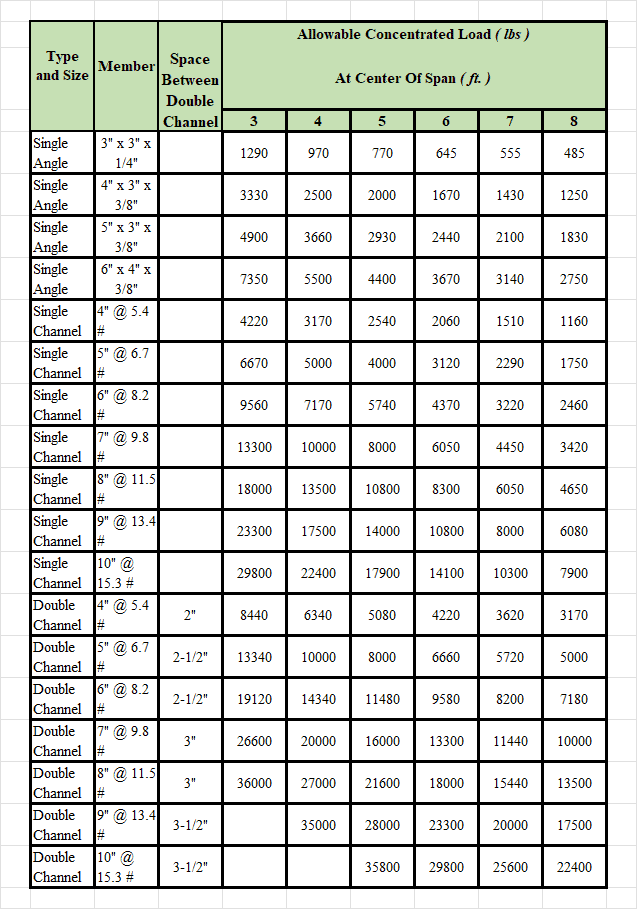
Angle Iron Span Chart
The table below lists the maximum Allowable Concentrated Load (lbs) a single angle, single channel, or double channel can carry when the load is applied at the center of the span. The numeric columns are span lengths in feet (3–8 ft); a dash (—) means no rating is published for that span.
| Type | Member | Space Between Double Channel | 3 ft | 4 ft | 5 ft | 6 ft | 7 ft | 8 ft |
|---|---|---|---|---|---|---|---|---|
| Single Angle | 3" x 3" x 1/4" | — | 1290 | 970 | 770 | 645 | 555 | 485 |
| Single Angle | 4" x 3" x 3/8" | — | 3330 | 2500 | 2000 | 1670 | 1430 | 1250 |
| Single Angle | 5" x 3" x 3/8" | — | 4900 | 3660 | 2930 | 2440 | 2100 | 1830 |
| Single Angle | 6" x 4" x 3/8" | — | 7350 | 5500 | 4400 | 3670 | 3140 | 2750 |
| Single Channel | 4" @ 5.4 # | — | 4220 | 3170 | 2540 | 2060 | 1510 | 1160 |
| Single Channel | 5" @ 6.7 # | — | 6670 | 5000 | 4000 | 3120 | 2290 | 1750 |
| Single Channel | 6" @ 8.2 # | — | 9560 | 7170 | 5740 | 4370 | 3220 | 2460 |
| Single Channel | 7" @ 9.8 # | — | 13300 | 10000 | 8000 | 6050 | 4450 | 3420 |
| Single Channel | 8" @ 11.5 # | — | 18000 | 13500 | 10800 | 8300 | 6050 | 4650 |
| Single Channel | 9" @ 13.4 # | — | 23300 | 17500 | 14000 | 10800 | 8000 | 6080 |
| Single Channel | 10" @ 15.3 # | — | 29800 | 22400 | 17900 | 14100 | 10300 | 7900 |
| Double Channel | 4" @ 5.4 # | 2" | 8440 | 6340 | 5080 | 4220 | 3620 | 3170 |
| Double Channel | 5" @ 6.7 # | 2-1/2" | 13340 | 10000 | 8000 | 6660 | 5720 | 5000 |
| Double Channel | 6" @ 8.2 # | 2-1/2" | 19120 | 14340 | 11480 | 9580 | 8200 | 7180 |
| Double Channel | 7" @ 9.8 # | 3" | 26600 | 20000 | 16000 | 13300 | 11440 | 10000 |
| Double Channel | 8" @ 11.5 # | 3" | 36000 | 27000 | 21600 | 18000 | 15440 | 13500 |
| Double Channel | 9" @ 13.4 # | 3-1/2" | — | 35000 | 28000 | 23300 | 20000 | 17500 |
| Double Channel | 10" @ 15.3 # | 3-1/2" | — | — | 35800 | 29800 | 25600 | 22400 |
Be the first to know about updates at CNC Cookbook
Join our newsletter to get updates on what's next at CNC Cookbook.