A client recently inquired about finding the Feeds and Speeds for Trochoidal Milling using the G-Wizard Calculator. G-Wizard excellently facilitates the discovery of these Feeds and Speeds, but initially, one must understand what Trochoidal Milling signifies.
Trochoidal Milling is a High Speed Machining (HSM) technique that moves the cutting tool in a shape called a "Trochoid." The link shows the derivation of what a Trochoid is, but here's a typical Trochoidal Tool Path for slot milling:
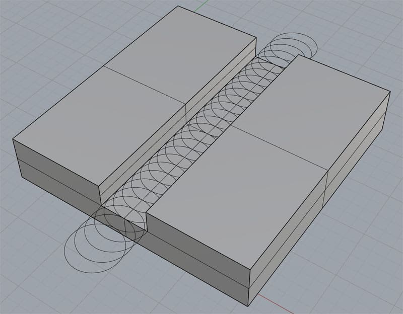
Using Trochoidal Milling for slot milling...
The idea is each cut consists of continuous spiral tool paths rather than moving down the slot in a straight line as you would with Conventional Milling. The advantage of Trochoidal Milling is it keeps a constant load on the cutting tool so you can run higher feeds and speeds. Some Trochoidal paths create a more "D" shaped tool path and don't do a complete circle each time, which can be faster than the full circles.
Here's what we mean by keeping a constant load on the cutter. The load is determined by how much of the circumference of the cutter is involved in the cut, also called the "engagement angle". Constant Load tool paths have Constant Engagement Angles. Conventional Toolpaths have much higher loads in corners. You can see that graphically via this illustration:
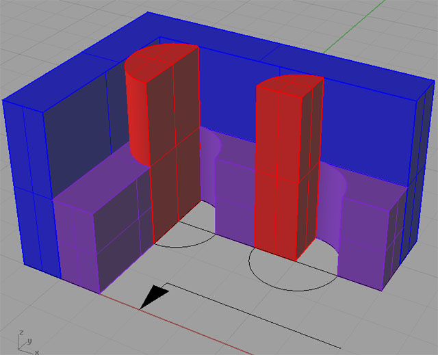
See how engagement increases dramatically as the cutter goes into a corner...
While some refer to all HSM constant engagement tool paths as "Trochoidal", the term specifically relates to paths that follow the continuous spiral tool paths shown in the first diagram. As such, Trochoidal Milling is most commonly used to cut slots.
Like all HSM-style toolpaths, the constant load means we can use higher feeds and speeds. But, one disadvantage of Trochoidal Milling that some worry about is that all that motion puts a lot more wear and tear on your CNC machine's ballscrews and slideways, particularly when you consider the much faster feeds and speeds involved.
In the end, there's a lot of motion associated with a Trochoidal Tool Path, but the motion can be faster than with a normal Toolpath. The benefit is typically 20% or more improvement in cycle time, but the biggest benefit is from longer Tool Life. The Improved Tool Life benefit is even better for tough materials like Titanium.
Trochoidal Milling typically trades lower radial depth of cut for increased axial depth of cut. The low radial depth of cut means the cutting edge faced reduced heat and reduced cutting forces. The increased axial depth of cut spreads the wear across a greater length of cutting edge, which also prolongs tool life. Ideally, you could use the entire length of the cutting edge. This in turn reduces the overhead of multiple passes and further speeds the machining operation.
Tough Situations: Micromachining, Tough to Machine Materials, and Unstable Workholding
Trochoidal Milling Techniques are often most helpful for challenging machining situations such as Micromachining, Tough to Machine Materials, and Unstable Workholding. We've already mentioned the Improved Tool Life advantages for Tough Materials. Give your cutting tools a fighting chance by using a more sophisticated tool path!
Like all HSM tool paths, trochoidal milling will reduce the cutting force spikes due to running into corners. Therefore, it can be helpful for micromachining, where such spikes often easily break small tools. However, there is a tradeoff. You're using smaller diameter tooling to mill a slot using Trochoidal Milling. Smaller diameter tools are more delicate. It may be more advantageous to skip Trochoidal Milling of a slot and just use a larger diameter cutter to get the slot done in multiple passes.
What about Unstable Workholding? By that I mean cases where cutting forces must be lowered because of thin walls, chatter, or inability to clamp and hold a workpiece tightly enough. Trochoidal Milling generates lower cutting forces at given material removal rates so it is ideal for these situations.
In really extreme cases, where we must reduce cutting forces at the expense of Material Removal Rates, we find that we can reduce cutting force by as much as 60% while keeping Material Removal Rates within 20% of conventional milling methods. That can be an exceptional advantage in a difficult machining situation such as machining thin walls or very deep pockets with small diameter tools.
Max Cutter Diameter for a Given Slot
To make sure there's plenty of clearance for Trochoidal Milling to work its magic, it's recommended that the cutter diameter be no larger than 70% of the slot width.
Trochoidal Milling Feeds & Speeds
Now how do we use G-Wizard Calculator to figure out the Feeds and Speeds for such a path?
Actually, it's pretty simple. Here is one all set up:
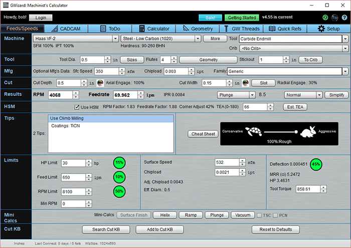
Feeds and Speeds for a Trochoidal Milling operation to cut a slot...
First, you set up the machine, material and tool. We're cutting some mild steel with a 1/2" 4 flute carbide endmill.
Next, you need to tell it the cutting conditions. We're doing a 1/2" deep slot, so I went with a full 1/2" of cut depth. Our cut width, radial depth of cut, or stepover is important because it governs how much we can accelerate due to High Speed Machining. The less of the tool that's in the cut, due to smaller stepover, the faster we can go. But there's a tradeoff. If you make the radial depth of cut too small, the cutter goes spinning through the material crazy fast but it doesn't accomplish all that much and the MRR falls. Most authorities suggest 10-30% of tool diameter as a good starting point. You can fiddle with it from there, keeping an eye on the MRR, until you find a value that suits your needs. For this example, I chose a 30% stepover, or 0.150".
Okay, the last step is to turn on the HSM Feeds and Speeds feature of G-Wizard. Just click the "Use HSM Feeds and Speeds" checkbox and your Feeds and Speeds are updated. We can see an RPM Factor and a Feedrate Factor that are each close to 2. That means that since we can guarantee this is an HSM tool path that will keep a constant TEA, both the RPM and the Feedrate can be bumped up to nearly 2 times the conventional feedrates.
Wow! Those HSM toolpaths move right along, don't they? For more on Feeds and Speeds for HSM Machining, try our Feeds and Speeds Tutorial chapter on HSM. In this case, we're getting an MRR of 5.2 cubic inches of material per minute and running about 3.5 Horsepower into the cut.
Want to calculate your own HSM Feeds and Speeds? Unfortunately there are no good cutting speed formulas to do that. You really do want a tool like G-Wizard to use these techniques. And BTW, the lower cut widths used by these tool paths mean low radial engagement which can lead to chip thinning. With low radial engagement, you must increase your feed rate to achieve the same chip thickness you were expecting. The linked article explains why, but chip thinning adjustment is just one more think our G-Wizard Calculator takes care of automatically for you.
How About Optimizing Trochoidal Milling Even Further and More Easily?
That's a conventional Feeds and Speeds Calculation of Trochoidal Milling, but G-Wizard can do an even better job for you using a feature called "Cut Optimizer". The idea behind "Cut Optimizer" is to find the maximum width of cut (or depth of cut, or feedrate, it's multipurpose) that can be used without too much Tool Deflection. This feature is unique to G-Wizard, you can't get it elsewhere, and it sure is powerful.
Note: Here's a full article on how to optimize your Depth of Cut and Stepover for CNC Milling.
While many authorities tell you as I mentioned to use 10-30% of diameter for stepover, check out what happens when we use the Cut Optimizer to maximize our stepover:
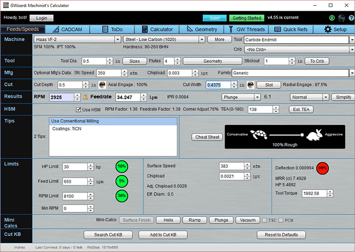
We've pushed the Cut Width up to 0.4375, which is 87.5% of diameter. As a result, or Material Removal Rate is now 7.4928 and we're using about 5.5 spindle horsepower.
Why is this much higher stepover outperforming the recommended 10-30% stepover numbers?
Here's the thing:
We can go faster with an HSM toolpath because we aren't slamming into any corners that shock the tool. But that says little about stepover. The role of reduced stepover is twofold. First, it unshrouds the flutes of the cutter so chips can be flung out of the cut radially-they don't have to be carried up and out by the helix. Second, we give the flutes more time exposed to air instead of cut, and they get a chance to cool off a bit.
But there's a trade-off. Those advantages are traded off against the fact that we're cutting less material per revolution with lower stepovers. What G-Wizard has done here is found a sweeter spot than the usual recommendations.
Some sources are starting to recommend larger stepovers for softer materials, but we were one of the first because of the ability to simulate these things with G-Wizard.
To get maximum performance from Trochoidal Milling Techniques, you need a package like our G-Wizard Calculator.
If you'd like to try G-Wizard Calculator for yourself, hop on over to the GW Calculator home page for a free 30 day trial.
Improve My Feeds and Speeds For


Be the first to know about updates at CNC Cookbook
Join our newsletter to get updates on what's next at CNC Cookbook.