It's time to progress with the Machinist's Hammer project. I am manually penning the g-code for this undertaking, without resorting to CAM software. Given the straightforward nature of this project, it's quite hassle-free. Furthermore, a wide range of productivity aids are available that facilitate faster and simpler transference of ideas from pencil to yellow pad.
Whenever I'm getting ready to start a new project, I like to have a dimensioned drawing on hand. Technically dimensions are not needed with CAM software as it measures them directly. However, I find it is tremendously helpful to have the dimensions anyway just to make it easier for me to see what's going on and to identify any mistakes faster. So, here's the dimensioned drawing of our T-Hammer, as I've taken to calling it:
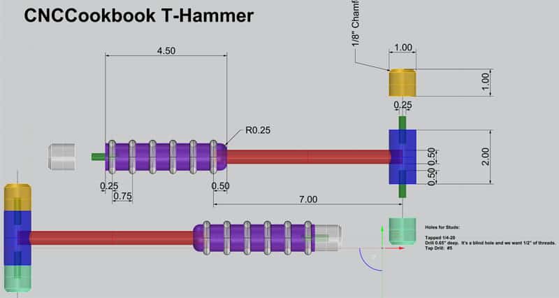
Dimensions for the Machinist's Hammer...
You're welcome to download my Rhino3D drawing of the hammer if you'd like as well, just click this link.
With a dimensioned drawing in hand, the next step is to organize the g-code programming. I like to put together an Excel spreadsheet to help keep my g-code work organized and make sure I'm covering all the bases. I use a format like this for the worksheet:
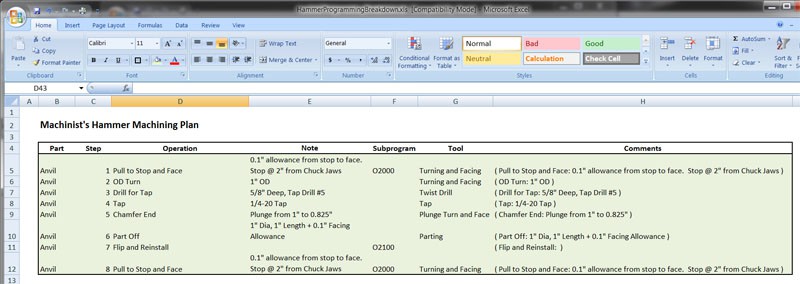
My G-Code Programming Worksheet...
Think of the worksheet as an outline of what the finished g-code program will need to do. I include a schedule like that for each of the hammer's parts-Anvil (the interchangeable faces), Head (what the Anvil's screw into), Neck (connects the head to the handle), and Handle.
The worksheet uses the following columns:
Part
Tells which part we're working on.
Step
I number the machining steps.
Operation
Description of what's to be done in that step.
Note
The details, such as dimensions or thread information about that operation.
Subprogram
Preliminary thinking about subprograms, if any, that will be used. I just assign them a number and use another page of the spreadsheet to keep up with them.
Tool
Identifies the tool that will be needed for the operation. I like to have no more than one tool in an operation and will the operation if multiple tools are needed. So, I have a "Drill" and then a "Tap" operation instead of a "Drill and Tap". This is really a matter of your choice, but it's easier for me to keep track since I'll be doing manual tool changes on a Quick Change Toolpost for this project.
Comments
These are not comments about the step, they are the comment that will go into the actual g-code program to describe the step. Once you're in Excel its easy to create these with string formulas.
You can download the G-Code Worksheet for the Hammer here if you want to follow along.
G-Code Outlines
Once I'm happy that the worksheet has captured all the important information needed to give a good overview, I cut and paste those comments to create the initial program for each part. They won't do anything yet because there is nothing but comments in them, but they provide the scaffolding that the real programming will be done against. Of course I like to use my G-Wizard G-Code Editor to do the actual programming, so I needed to set up a Machine Profile for the Tormach lathe. It's very easy to do with specs from your machine's documentation or their web site. I got my data from Tormach's spec writeup on the lathe, here's what that looks like:
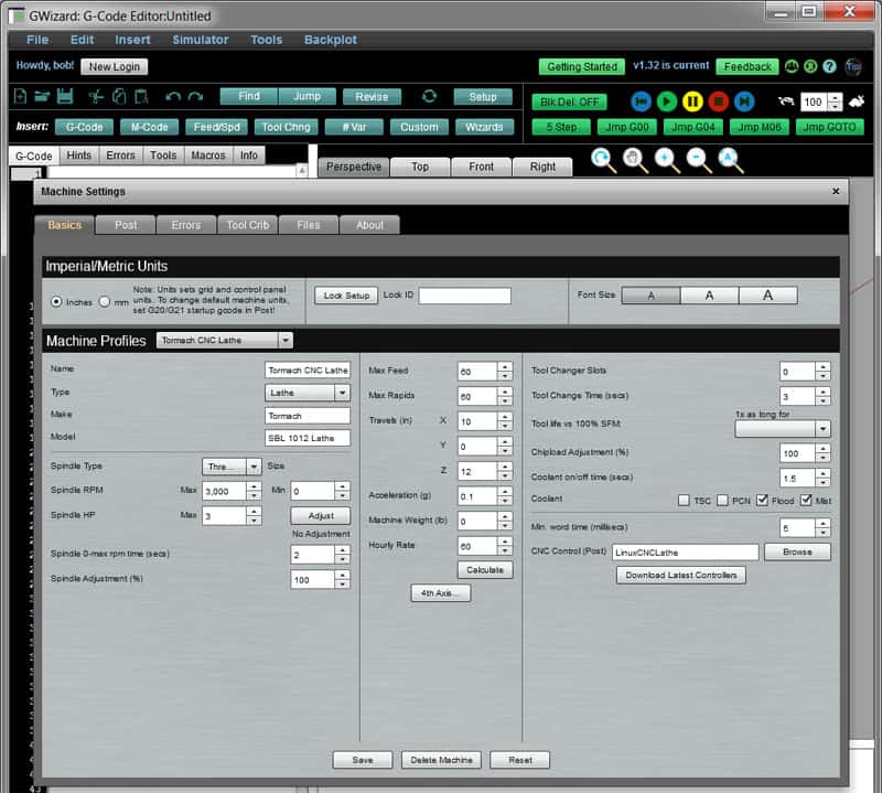
G-Wizard Editor Machine Profile for my Tormach CNC Lathe...
And here's what the initial g-code scaffold looks like for the Anvil:
( Pull to Stop and Face: 0.1" allowance from stop to face. Stop @ 2" from Chuck Jaws )
( OD Turn: 1" OD )
( Drill for Tap: 5/8" Deep, Tap Drill #5 )
( Tap: 1/4-20 Tap )
( Chamfer End: Plunge from 1" to 0.825" )
( Part Off: 1" Dia, 1" Length + 0.1" Facing Allowance )
( Flip and Reinstall: )
( Pull to Stop and Face: 0.1" allowance from stop to face. Stop @ 2" from Chuck Jaws )
G-Code Building Blocks and Code Snippets
Now you've got a good outline for what your g-code program needs to do. Think of each of those comments as a building block. Each one is a small programming project in and of itself. We're doing a divide and conquer here: keep breaking things down into smaller and smaller steps until each step is easy enough we can code it quickly and move on. This is what software developers call "Top Down" programming, and it's an excellent way to approach g-code programming.
Something you're probably noticing about now is that there is a lot of repetition among these building blocks. I called out a little bit of it by assigning subprogram numbers. But there's more. This is very common in machining because a lot of parts have symmetry and they have duplicated features. You can take advantage of it by only writing each code snippet once and then calling the same snippet as a subprogram from multiple places.
While we're on the subject of code snippets, I should mention G-Wizard Editor's Custom Cycles. I can't tell what the part is in the Anvil code above, so I need to add a Header Block to my program that has some basic information. It so happens I've defined a Custom Code Snippet in GWE for that:
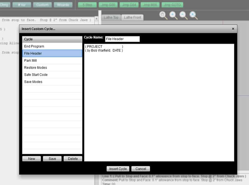
Custom G-Code Snippets are found under the "Custom" toolbar button...
Custom Snippets, or Custom Cycles if you prefer, are very easy to use. You use the popup to insert them into your code and to create, edit, or delete them from the library. Over time, if you do much hand programming, you'll start to build up your own library of snippets. Okay, here's Anvil's g-code again with a header pasted in:
( T-Hammer Anvil )
( by Bob Warfield. 12/8/2013 )
( Safe Starting Conditions )
G0 G40 G49 G50 G80 G28
( Pull to Stop and Face: 0.1" allowance from stop to face. Stop @ 2" from Chuck Jaws )
( OD Turn: 1" OD )
( Drill for Tap: 5/8" Deep, Tap Drill #5 )
( Tap: 1/4-20 Tap )
( Chamfer End: Plunge from 1" to 0.825" )
( Part Off: 1" Dia, 1" Length + 0.1" Facing Allowance )
( Flip and Reinstall: )
( Pull to Stop and Face: 0.1" allowance from stop to face. Stop @ 2" from Chuck Jaws )
You'll see I also inserted a "Safe Start Code" snippet right below the header. This just ensures some basic assumptions about start up conditions for the part.
Pull to Stop and Face
Looking down the list of steps, the very first one we haven't filled in is "Pull to Stop and Face". The idea here is that we move the tool tip to X0Z0 and stop. The machinist unlocks the chuck and pulls out the stock until it just touches the tool tip and then relocks the chuck. Think of it as a poor man's manual bar pulling arrangement. It's just an easy way for the program to know starting conditions. You will need to make sure Z0 leaves enough room for the part in the Z-axis (lengthwise) dimension. In this case, we're saying we want 2" from chuck jaws, which should be plenty for a 1" part with some allowance for facing and parting on either side.
We're going to immediately face the workpiece to Z = -0.1" because we know our stock is accurate to 0.1" or less, so that'll give us a trued up face at one end of the part at Z = -0.1". That's a reliable foundation from which to make the rest of our part. In this case, that face is going to be the end of the anvil that has the threaded hole used to afix the anvil to the stud in the hammer's head.
This all seems great, and you can see that we use a "Pull to Stop and Face" operation quite a lot. So, I'm going to make a custom code snippet for the purpose. Here's what it looks like:
( Pull to Stop )
X0Z0
M0 (Program stopped: Operator, please pull stock to stop and start program.)
Not much to it. The machine runs to X0Z0 and then the program stops. The comment is there to tell the operator what to do: pull the stock out to the stop and hit the green button to start again. I stuck that in as a Custom Code Snippet because I know I'll use it again many times. I debate whether to add a G00 to it, but I'm going to make my convention that the snippets expect G00 and will change to another motion mode if needed. That's much safer than assuming the other way around and inadvertantly leaving a G00 active for what should be a feedrate cutting motion!
Next step is the facing operation. We're just going to shave off a max of 0.1". I'm thinking of doing that in 3 passes:
- Z0.0
- Z-0.040
- Z-0.080
- Z-0.100 (Finish pass, only 0.020")
For this particular pass, we have a target diameter of 1" and we leave a stock allowance of 0.1" on top of that, so we can start the facing pass at anything over 1.1". Here's our facing code:
( Face. Stock's at 0.0
X-1.4 ( Leave a nice big margin in X )
F14 S800
M3 G01
( Z0.0 Roughing Pass )
Z0
X0.0
( Z-0.040 Roughing Pass )
G00 X-1.4
G01 Z-0.040
X0.0
( Z-0.080 Roughing Pass )
G00 X-1.4
G01 Z-0.080
X0.0
( Z-0.100 Finishing Pass )
G00 X-1.4
G01 Z-0.1
X0.0
G00 X-1.4 (Done Facing)
The experienced g-code hands out there will be thinking, "Hang on, why is he hard coding this for just this one facing situation, why not make this a more general routing with some parameterized programming?"
The answer is I am trying to keep this code super simple for beginners to understand, and I am also trying to keep it simple so it'll run on nearly any control regardless of g-code dialect. I'll leave it as an exercise to the reader to create a fancier version where you can set a diameter, roughing depth, finish depth, feeds, speeds, and so on. BTW, I used G-Wizard Calculator to set up these feeds and speeds which are very much on the conservative side.
There are other ways to generate g-code besides using CAM or writing it by hand. You can also use a Conversational G-Code Wizard to generate code. The Tormach Lathe has a bunch of these handy gadgets built in for doing basic lathe operations. The next step in the program is to OD Turn to 1" diameter for a length of 1". Here's what that looks like when set up in the Conversational Wizard:
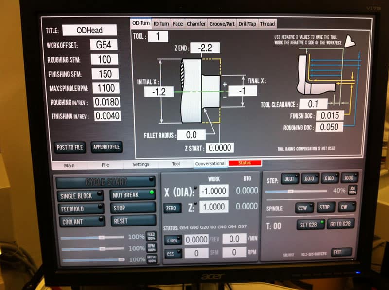
Tormach's OD Turning Converstional Wizard...
The Conversational Wizards are real easy to use. The OD Turn one pictured above is pretty obvious. Give it a few parameters:
- Title, feeds, speeds on left
- Tool
- Initial and Final X and Z
- Option Fillet
- Tool Clearance
- Rough and Finish Depth of Cut
The Wizard takes all that and cranks out some g-code:
(OD Turn G-code generated:)
( Mon Dec 2 17:02:59 2013)
(Units = G20 inches)
(Work Offset = G54)
(CSS Max. Spindle RPM = 1100)
(Tool Number = 1)
(Tool Type = ftp_turn)
(Tool Orientation = 3)
(Tool Radius = 0.0158)
(Rough CSS = 100 feet/minute)
(Rough Feed inches/revolution = 0.0180)
(Rough Depth of Cut = 0.0500)
(Finish CSS = 150 feet/minute)
(Finish Feed inches/revolution = 0.0040)
(Finish Depth of Cut 0.0150)
(Initial Diameter = -1.2000)
(Final Diameter = -1.0000)
(Z Start Location = 0.0000)
(Z End Location = -1.2000)
(Fillet Radius = 0.0000)
(Tool Clearance = 0.1000)
(Tool on - side)
G7 (Dia. Mode)
G18 (XZ Plane)
G90 (Absolute Distance Mode)
G20
G54
(Set Roughing Parameters)
(CSS, Spindle - feet/minute, Maximum RPM)
G96 S 100 D 1100
(Feed Rate - inches/revolution)
G95 F 0.0180
G28
T0101
M3
M8
(Number of roughing passes = 2)
(Adjusted roughing DoC = 0.0425)
G0 X -1.2000 Z 0.1000
(Pass 1)
G0 X -1.1150
G1 Z -1.1850
G1 X -1.2000
G0 Z 0.1000
(Pass 2)
G0 X -1.0300
G1 Z -1.1850
G1 X -1.1150
G0 Z 0.1000
(Set Finishing Parameters)
(CSS, Spindle - feet/minute, Maximum RPM)
G96 S 150 D 1100
(Feed Rate - inches/revolution)
G95 F 0.0040
(Finish Pass 3)
G0 X -1.0000
G1 Z -1.2000
G0 X -1.2000 Z -1.1000
G0 X -1.4000
G0 Z -1.2000
G1 X -1.0000
G0 X -1.4000 Z 0.1000
G28
M5
M9
M30
By default, the code is set up to run as a stand-alone program since I just had it save to a file. We'll need to edit it down a bit to get what we want, but the Wizard did an awful lot of our work for us. Incidentally, it only took me about 15 minutes to run through all the Wizard work I needed and collect the code snippets onto a USB key. The combination of the Wizards being easy to use and my Excel Worksheet having gathered up all the key information so it was at my fingertips made cranking out that g-code fast and easy.
Not all controls have Conversational Wizards, but G-Wizard Editor has a bunch of them built in too:
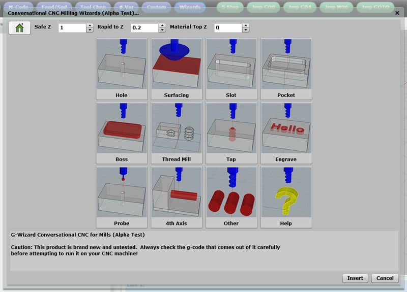
Conversational G-Code Wizards in G-Wizard Editor...
As I write this, the Conversational Wizards are all for mills and there aren't any for lathes yet, but they'll be coming along soon.
I'm going to end this article here. There's not a lot left for the Anvil code-Drill, Tap, and Chamfer. I used the Conversational Wizards for Drill and Tap, and I'll do the Chamfer with a simply plunge move. I'll finish going over the final g-code and show an Anvil being made in the next Machinist's Hammer article.
Be the first to know about updates at CNC Cookbook
Join our newsletter to get updates on what's next at CNC Cookbook.