Did you once find CAM Software as perplexing and exasperating as I did?
I remember when I first started messing around with CAM. It was before I got my CNC mill up and running and a little while after I had gotten reasonably proficient with CAD. I got hold of some free trials and couldn't believe how hard it all seemed. Much worse than CAD.
The CAM program was constantly asking me mysterious questions I had no idea the answers to, or it would seem as though the CAM software didn't understand my 3D model from the CAD package quite right, or sometimes it would just do absolutely nothing and I couldn't figure out why. It wasn't just one CAM package, but three or four that did this. Eventually I figured them out after watching lots of videos and doing lots of experimentation.
Recently, the subject of CAM Software for beginners came up again from several sources and I was reminded of my own original experience. Basically what I was hearing was the same story I had gone through. Part of the problem is that beginners have entirely the wrong expectation:
After working hard to learn CAD and having labored to produce a beautiful 3D model of the desired part, they want to just load that model into their CAM Software, push a button, and instantly get a g-code program out of it.
Unfortunately, nothing could be further from the truth of how CAM software works. I have never seen a single CAM package that will do what the beginner expects, but some are easier than others. Think of your CAM software as being a helpful assistant that has to ask you a lot of questions before it can get on with doing the job of producing your g-code. Usually, the more sophisticated the CAM package, the more questions it wants to ask.
Because of that, I encourage beginners to start with the simplest possible CAM package. Even if you can afford a very expensive "Pro" package to start, skip it until you've gone down the complete path to make a few parts with a simpler package. The simpler package may not be the only package you'll ever need, but it will carry you plenty far enough for longer than you'd think. What you'll learn along the way will make it far easier when you decide to go for the higher end package to actually get it to work. If you must start with a Pro package, I highly recommend lining up a full training program from a Community College or professional trainers experienced with the software you've chosen.
For the time being, let's assume you want to learn a package on your own, and that you're going to start with a simple package. Let me try to help.
BTW, this article is CAM-focused, but if you're a beginner, you may be looking for a full Starter Suite of CNC Software. Be sure to check out our article:
[ Best CNC Software for Beginners ]
It's chock full of awesome resources including buying guides, evaluation tips, and even secret deals to get the best software on the cheap that most people don't know about.
First, pick a simple part to experiment on
Let's don't start with a 5 axis turbo impellor please! Pick something very simple. I recommend what's called a "2 1/2 D" part. Such a part is flat on top, all the same height, though it may have holes (which we often call pockets). Here is a typical example of such a part:
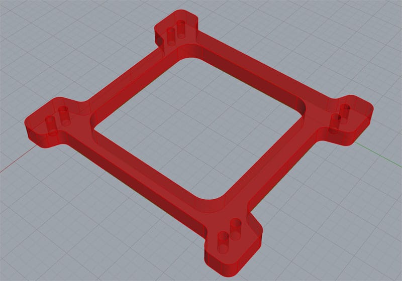
A Simple 2 1/2 D Part...
That's a carb spacer for a Holley Carburetor. Before you go diving into CAM, make sure you're reasonably proficient with your CAD software and can confidently make models like this one. Depending on the CAM package, it may accept 3D models or it may actually prefer 2D outlines. Here are the 2D outlines for the carb spacer:
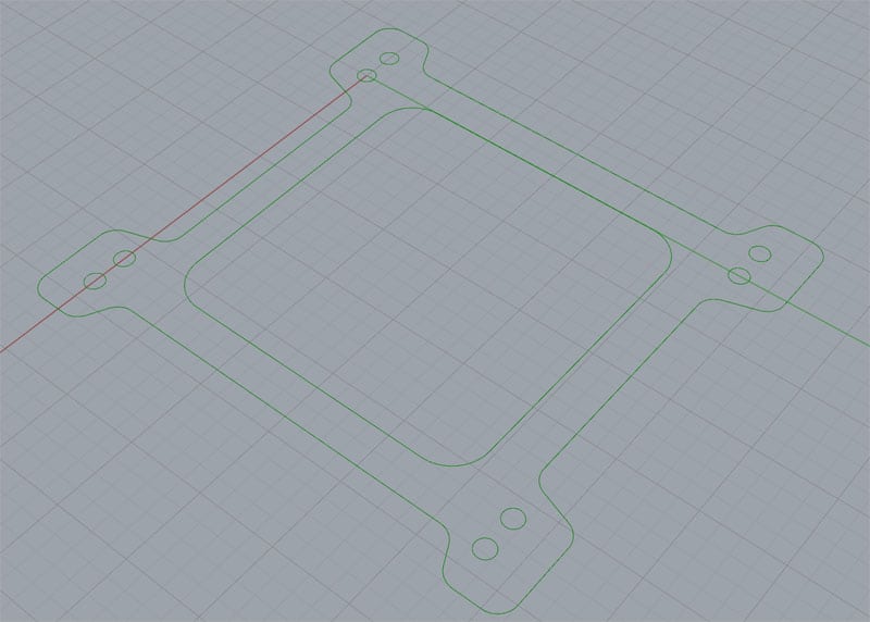
The outlines for the same part...
I much prefer working with 3D models myself, but a lot of the world is used to 2D, which is more like blueprints. Typically, we're talking about DXF (AutoCAD) files for outlines. There are many formats for 3D Models, including STL, IGES, STEP, and many others. The format doesn't matter too much, but it has to be something your CAM software can load and make sense of. One of the things I really like about the Rhino3D CAD package I use most often is it supports a great many file formats and can give me pretty much anything I need for some other software to load.
Second, get several trial versions and try them all
These CAM packages will all look pretty different to you when you're starting out. Get several 30-day trials so you can compare them back to back. Don't rely on someone like me to tell you which one to buy-you need to find the one that seems most intuitive to you and each of us is a little different. Take your simple part and run through using each CAM package to create g-code for it. Each successive package will get a little simpler to figure out as you'll have learned something playing with each one that applies to the others.
Watch Lots of Videos!
Now that you have all of this in hand, watch lots of videos on YouTube. Look for demos and tutorials for parts similar to the one you're using as your sample. Being able to actually watch someone use the programs makes it so much easier to learn them.
Track Down the Basic Concepts
While you watch the videos, get a handle on the Basic Concepts. As I mentioned, all CAM software asks lots of questions. Learning what these questions are gets you started "thinking like the CAM program," which will help you to better understand what's going on. The typical questions asked fall into certain broad categories:
Setup
Generally, you deal with this stuff once. It's all about telling the CAM program about your machine and controller so it produces the right g-code dialect for your machine and controller. These details are often referred to as a "Post" or "Post Processor". If you don't have the right post, you can get g-code that looks fine but produces bizarre results when you actually run it. Search this out and make sure you've set up the post right!
Feature and Toolpath Selection
Next up is Feature and Feature Selection. This is where you explain to the CAM software what the features on the part are and how to machine them. For example, the Carb Spacer Plate above has the following features:
- Mounting Holes, which we'll use a twist drill for.
- Center Square Cavity, usually called a "pocket".
- Outer Edge, usually called a profile.
- Top and Bottom. For a carb spacer plate, we'll want to machine these surfaces flat, an operations that's typically called "Facing."
Most CAM has a little menu of the types of toolpaths it can generate. You want to learn their terminology and what the different toolpaths do. You'll also want to learn what information about your part is needed by the toolpath. For some CAM, just select the edge and a pocket and it knows what it needs to. Others may ask more questions. We'll see in a minute when I demo a couple programs that the Profile operation may want to know which side of the outline to profile and which to leave alone. Such questions seem odd to beginners-can't it see the part? But no, CAM is not as smart as we wish.
FWIW, some packages can "see" the part. They use sophisticated algorithms called "Feature Recognition." MeshCam, the super easy CAM software we sell here at CNCCookbook is one such. It is good enough at it that you can just about skip the Feature and Toolpath selection. As you'll see in the demo, you still have to answer the other questions, but skipping this step can really simplify things and make it faster and easier to get your part done.
Style Parameters
Style is an odd choice of words, but I couldn't think of a better one. These CAM programs all have lots of options that, for want of a better word, change the style of how things are done. They let you change things like, "Where is Part Zero (Program Zero)?", and so on. Try leaving these to their defaults.
Cut Conditions and Stock
Somewhere in all the questions the program will need to understand the cut conditions and the rough stock. What does the block of the material look like before we start cutting into it? Ideally, the program actually has "stock" as a first class concept. You'll see in the demo video how Meshcam does this. If not, you may have to implicitly define the stock by answering questions about where the top of stock is, how deep you're cutting, and so on.
The cut conditions boil down to width and depth of cut, and the impact these have on how many passes must be made to cut out the full part. One other cut condition has to do with whether you'll do a finish pass or not. Skip them at first until you get roughing to work. The finish pass is something you'll want when you actually make a part, but before that time, it's just one more complication. Walk before you run.
Feeds and Speeds plus Entry and Exit
Feeds and speeds are absolutely critical. Unfortunately, just about all CAM packages do a lousy job with it. Do yourself a favor and get a good feeds and speeds calculator. Obviously we recommend G-Wizard Calculator, but almost any commercially available feeds and speeds calculator is better than almost anything built into a CAM package.
A really good feeds and speeds calculator will help you answer the Cut Conditions questions-what's the best Cut Depth and Cut Width. Right now, G-Wizard is one of only a very few I have seen that do that.
Entry and Exit are questions these programs ask, perhaps more the Entry than the Exit. Typically you can't just plow into the material at full speed. You have to ease the cutter in. There are a lot of fancy techniques around this, and I talk more about it in the Feeds and Speeds tutorial. For getting started, just use a simple plunge. You'll need to give it plunge feeds and speeds as well. This is automatic in G-Wizard, but a lot of calculators don't give plunge numbers. Make sure yours does.
Other
Tired of answering all of those CAM questions yet? I know I am-phew!
There are tons of other questions these programs will ask. Most of it can be left to defaults until you really need to make the program behave differently. When in doubt, leave the default. Try it. See what the toolpath looks like. Over time, you'll want to learn what all those little options do as they may come in handy some day.
Using MeshCam and Cambam to Make the Same Part
Let's see all of this in action for two popular entry level CAM packages. I have put together video demos that show how to get each package to produce g-code for our carb spacer. This will give you a good idea of how the two compare and how to get started with other CAM packages to do similar work.
MeshCam
Cambam
Conclusion
Hopefully you had a chance to see both videos and saw both CAM Packages being used to make the same part. MeshCam is a lot simpler and less cluttered. More things are automatic. Cambam is more complex. It asks more questions. In the end, it produces g-code that runs a little faster than the MeshCam g-code. This is fundamentally the tradeoff in complexity versus performance that's being made. I am a big believer in getting beginners productive and making parts as quickly, easily, and cheaply as possible. Once you're able to make parts at will, then we can investigate how to do it better. Neither one of these packages is very expensive to get started with. Neither one is likely to be a package that suffices throughout your entire machining career. Chances are you will want to upgrade at some point to a package that's quite a bit more expensive. That's fine. Don't bite off the expensive package up front, though. Why deal with all the complexity and cost?
If you'd like to try Meshcam out, there's a free trial available. Like I said, make sure you've got some CAD under your belt before diving into CAM, but if you're ready, give Meshcam a try. It's a very neat little package. I have had several experienced pros say they like to use it for quick and dirty things like one-off fixtures just because it is so quick and easy compared to their fancy high end pro packages.
If you want to learn more about free alternatives, check our Guide to Free CNC Software.
Be the first to know about updates at CNC Cookbook
Join our newsletter to get updates on what's next at CNC Cookbook.