To begin, it should be stated that this article does not focus on fixing issues with a non-functioning machine. There exist instances where commands, sent to a well-adjusted and configured CNC machine, do not yield the desired movements.
How can that be possible?
The short answer is that this is caused because there are many approximations and assumptions made every step of the way from your conception, to CAD drawing, to CAM program, to G-Code, to Trajectory Planning in the Controller, to the Servos or Steppers driving the axis, to the leadscrew and other components driving the table, and so on.
There are various techniques that are used to minimize these errors, but it is useful to be aware of their sources, so let's look at a few of them. This diagram includes a few examples of each:
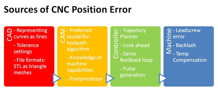
Sources of CNC Position Error...
From Conception to CAD File: CAD Errors
In your mind's eye, you see a very pure shape. Circles, cylinders, smoothly flowing lines, all with infinite precision. The CAD program has to render these notions with more limited means. Perhaps it can only represent lines, and hence arcs and circles become a series of short line segments that approximate the arc. Perhaps it can represent splines, but the curve you have in mind is only approximated by the spline.
Some file formats make fairly extreme assumptions. Perhaps your carefully constructed 3D model, which had smooth flowing curves and other geometries, is being represented by the file format as a mesh of triangles which can only approximate the original model.
In these cases, the CAD program is approximating what you've asked for, and there will be errors and assumptions made in that process. You have a little bit of control over it. You can choose to use a better CAD program. There are settings in most of the CAD programs that govern the degree of error their approximation is supposed to allow.
From CAM to G-Code: CAM Errors
The next step in the journey from conception to making chips is to load your CAD model into your CAM program. Even if they're integrated, there may not be a lot of difference in the end result. The CAM program wants to think about your model in a certain way to do its job. That certain way may or may not be highly compatible with what the CAD model can actually offer.
If nothing else, the CAM program is applying cutter geometry to the model. There is no cutter geometry that corresponds to a mesh of triangles, so if that's what the model offers, the CAM program is going to approximate.
Perhaps the toolpath algorithm itself is doing some sort of approximation of your geometry. Was it easier for the software engineer that wrote the toolpath code to think of your arcs as a bunch of short line segments? If so, he will have converted your arc geometry to line segments to facilitate his task.
If he used enough line segments, the approximation will be accurate enough for your purposes. But, of course, there are tradeoffs. Fewer segments means faster algorithms. If you don't check your default tolerances in the software, you may find the compromise between speed and accuracy chosen is not a good one for the job you have at hand.
Perhaps it was easier to ignore some commands that are available on your machine and controller and go with a simpler post processor. Many post processors have the option to view arcs as lots of line segments.
Many will simulate canned cycles rather than having to be fully aware of the many varieties available on the many controllers out there (not to mention what optional parameters may be set on each controller).
Does your CAM program have any notion of what your machine is actually capable of? Does it know, for example, what sort of acceleration the axes are capable of?
Most CAM software does not. It accepts the programmer's idea of proper speeds and feeds (or worse many use a crude calculation of their own) and assumes that if the programmer says the feeds and speeds are okay that the machine can actually perform at those levels.
Of course the feeds and speeds are based largely on notions of what the cutter can handle in the given material.
Some operations are difficult because they will involve accelerations that the machine may not be capable of or that it may not be capable of pursuing accurately. A good example of a motion that's challenging for machines is helical interpolation.
Our G-Wizard Feeds and Speeds Calculator specifically considers available axis acceleration when suggestion feeds and speeds for helical interpolation. If we didn't, it would be hard to do accurate interpolations.
But most machinists are doing helical interpolation without worrying about acceleration. If they command it, the machine will do it, right?
Nope. There's a reason why this sort of motion is a common way to test a CNC machine. It tasks the motion with motions that make it most likely to expose vulnerabilities. To move in a straight line is not so bad.
But to describe a circle requires two axes to work in a perfectly coordinate way, accelerating, decelerating, and even reversing direction to go around the full circle.
If your CAM program generates g-code for a helical interpolation that is unaware of the machine's acceleration limits, the machine is simply going to do the best it can. If it happens to get around the circle without tripping a servo fault due to following error, you may think all is well, but your interpolated hole may not be very accurate.
From G-Code to Commanded Motion: Controller Errors
We're almost to the end of the journey as we present g-code to the controller whose job it is to convert that g-code into axis motions to cut our part. Unfortunately, we're also entering the realm where we may have the least control over what's happening and very little understanding of what the controller is doing.
We do know there are important considerations going on down inside the controller, though. We know, for example, that many manufacturers offer HSM options that make the controller more accurate for High Speed Machining. We know controllers will perform better if we give them arcs instead of thousands of tiny straight line segments because there is software available that will do arc fitting and machinists report that it helps. We know there are controllers like the Miceli and others that claim they can double the speed at which your machine processes a g-code program using the same servos and other components.
How can Miceli offer a money-back guarantee to double your machine's speed using the same servos? The only possible answer is that somehow other controllers are wasting the potential of those components in various ways. The same g-code goes into both controllers, but one is able to interpret that g-code and turn it into motion commands to the servos much more effectively than the other.
Consider the case of a zillion short line segments versus a smooth arc. Why is that harder and slower?
The g-code for each line segment has to be parsed and evaluated by the controller as it is moving the cutter. Say we are representing a 3" diameter circle to an accuracy of 0.0005" or half a thousandth. We can use G-Wizard's Chord calculator to figure out how many segments will be needed. A chord of height 0.0005" (the maximum error) for a circle of radius 1.5", will be 0.0775" long, will cover 2.9588 degrees of the circle, and hence we will need 122 segments (round up) to cover the whole circumference of the circle.
Suddenly, our g-code program will have 122x as many moves as it would if a single arc move could draw the circle. Let's say we have a very nice VMC that can interpolate very accurately and we want the same hole accurate to 0.0002". Doing that will take 193 segments.
What does that mean to the controller?
If you have the HSM option on your Haas controller, it can process 1000 blocks per second. At 150 IPM, your cutter can move 0.0025" per block if you have the HSM option. Put another way, if you have blocks that move less than 0.0025" but still require a feedrate of at least 150 IPM, the Haas control may not keep up if you give it enough of those moves and something has to give. Now that's a nice control with the added cost of an HSM option to speed up its processing. Imagine an older control without an HSM option.
Eventually, the control has to slow down the cutter in order to give it self enough time processing blocks to keep up. This situation becomes even more complex for 3D, which is also prone to lots of very short moves.
What controllers like Mach3 which are at the low end of the market?
Obviously they're going to process much more slowly than 1000 blocks per second. In addition, their trajectory planners are going to be correspondingly less sophisticated than that Haas control. And, they're going to try to operate by generating pulses via the parallel port unless a separate hardware motion control solution is being used. Mach3 uses a ring buffer which it fills with velocity commands for each axis. Suffice it to say that the ring buffer is subject to the same issues as having too many g-code blocks per second to process. If either one gets too full, the machine has to be slowed down in some way or we've got a problem. There are a lot of other problems that can crop up in Mach3's ring buffer and parallel port system as well. Some are discussed in our series linked to just above about hardware motion control.
Mechanical Errors: The Final Frontier
It's been a long journey. I'm reminded of those crazy films in school that show the entire journey of a bite of food through the body or some such. We are finally near the end. The trajectory planner on the controller is commanding our stepper or servo to make a move. Let's track through the different kinds of errors that accrue here.
First up-servo following error and lost steps. These are both the same thing in the end of the day: something happens that causes the motor not to be able to move the axis where it should be. Could be the force required for the motor to move exceeded its capacity at the particular rpm it was running at. For whatever reason, a move was commanded and it didn't happen. With a stepper-based system, that motion is lost. The cutter will be off by the amount of the lost steps until such time as we re-home the machine (a good argument to do so frequently in my mind!). With a servo-based system, the servo will try to get itself back on track. It will try to speed up when the resistance is reduced to catch up to where it should be, for example. If it can do that before the following error (total distance it is behind) becomes too great, all will be well, though our cut can be off by up to the amount of the allowable following error. Presumably we have set that small enough we don't worry too much.
If we get more than the following error on a servo system, the machine faults and the job is stopped. This is a good thing because we know we had a problem. On a stepper based system, it just keeps going. Given enough lost steps, things can get ugly. For example, if we lose steps each time we raise the spindle, the spindle will drop lower and lower each pass, which means a deeper cut, which can lead to more lost steps, and you can see how the vicious cycle unfolds.
As an aside, folks that like to say lost steps should never happen in a properly designed and operated machine are just kidding themselves. It sounds great, but in practice, the forces required to move the machine are too unpredictable. Every temperature change means the gibs are fitting a little differently which will affect the axis friction. Use or non-use of a one shot oiler matters a lot. "Sticktion" means short moves (there's those darned little line segments versus longer arcs again!) have radically higher friction than longer moves. I've seen on my servo based system how often servo faults come along even when I detune the machine a long ways from "optimal". The only difference is the stepper guys never see a fault, they just wonder why their parts aren't as accurate as they expected sometimes.
There are many other sources of error in the mechanicals. We may have backlash or other lost motion in our leadscrews. The leadscrew will have errors in its thread. The length of the leadscrew (and the other machine components) will change as the temperature changes. There is a long list of these things. The more sophisticated the machine, the more it will do to try to overcome these limitations. For example, the machine may have a set of glass scales mounted to each axis that give it continuous feedback on how far the axis is actually moving. The factory or service technicians may use a laser to precisely measure how far your leadscrew moves at every position of travel. This creates a leadscrew map that your controller can use to compensate for inaccuracies in the leadscrew. The machine may have temperature sensors located at various places to help it compensate.
If your machine doesn't have all these whizbang accuracy gadgets, you may be able to use a probe to deliver a lot of the same benefits. See our article about RAMTIC manufacturing for some ideas there.
Conclusion
By now, I hope I've been able to show that even though you may have commanded your CNC machine to make a move, and even though it may be in good working order, there are a host of subtle interactions that can get in the way and cause your machine to move with less than the accuracy you desire. There are a lot of techniques to help you get around these obstacles including:
- Being aware of the limitations of various CAD file formats like STL, and being on top of the tolerance settings used by your CAD and CAM programs.
- Being on the lookout for sources of errors generated within your CAM program. Try to use a post and CAM that allows for true arc commands rather than lots of line segments, for example.
- Being up to speed on your controller's limitations with respect to how quickly it can process blocks. Get yourself a curve fit program to reduce the complexity of some of your g-code, perhaps.
- Being aware of the many sources of error within your machine's mechanicals.
Experienced machinists compensate for these things in a variety of ways. They'll know that machines need to be warmed up before you can depend on them to hold tolerance. They come to know that they have to measure and compensate every nth part to deal with changes from tool wear, machine getting warmer, and so on. They'll have a good sense of what kind of tolerances they can hold on key operations, for example interpolated holes. They know how to use tools like the various offsets on the machine to compensate for differences between the features they measure on the parts and what the prints call for. And they will have honed the combination of their CAD/CAM and Post to get the most performance they can out of them over time.
It's challenging to wring the maximum performance out of such a combination, but it can surely be worth it in many cases.
Be the first to know about updates at CNC Cookbook
Join our newsletter to get updates on what's next at CNC Cookbook.