The Design
See the "Planning" section below for the ideas I studied before coming up with my design.
This is my 2nd design, and its based on comments and feedback from various articles and conversations with other machinists about their swing arms. Here is the assembled arm drawing:
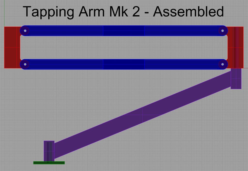
The Mk2 consists of the following components:
- Left and right swing blocks (red): CNC machined from 3/4" 6061 aluminum plate
- Parallel arms (blue): Cut and machined from 1" square tubing
- Upright (purple): Welded together from bits of steel or aluminum. The pivot points are 1" square, and the connecting plate is 1/4"
- Mounting base (green): Welded together from a piece of 3 1/4" x 3 1/4" x 1/4" thick plate and the pivot rod which is 1/2" diameter.
I will probably use a gas spring connected between the lower right and top left pivot points to support the parallelogram linkage and a butterfly impact wrench to do the actual tapping. The bracket that holds the impact wrench is not shown.
A Word About Fixturing and Setups
This project is done with minimal fixturing-just a block so I can bolt down the swing blocks with 1/4-20 bolts. Both the fixture, and the rest of the setups, assume 0, 0 is the vise's fixed top jaw, lower left corner. This makes for real easy setups (especially if your machinist vise sits on your mill table most of the time) and is a trick I learned from my friend Peter, who owns a machine shop in Hawaii.
Machine work starts by tramming your vise in, and then indicating that 0, 0 position so you can set 0 on your machine.
Swing Blocks
The swing blocks will be made using a fixture so they can be bolted down with 4 1/4" bolts and their entire side surface will be available for profiling.
The fixture is just an aluminum block that sits in the vise with 4 matching thread holes for the 1/4-20 hold down bolts.
When machining the swing blocks and fixture, we will use the fixed (top) vise jaw corner as the 0, 0 point. This makes it easy to drop the workpieces into position repeatably, at least as long as the vise hasn't moved and I have zeroed on that corner with an edge finder.
G-Code to drill the 4 bolts holes in either the fixture or swing blocks
The first step is to drill the fixture plate, and 2 swing block plates. For the fixture plate, we want the 1/4-20 tap drill size, which is a #7 (0.201") twist drill according to G-Wizard. I like to use screw machine length bits because they don't have to be spotted in aluminum due to the short length.
For the swing blocks, we'll use a 1/4" bit.
Next step is to thread the 1/4-20 holes in the fixture. I like to use my little butterfly impact wrench with a tap adapter to make short work of it.
Now that we have a fixture block and 2 swing blocks with holes, its time to profile the swing blocks. Stick the fixture block in the vise aligned to the fixed jaw's left corner. Bolt a swing block down on top. Note that the holes only allow it to go in one direction.
We're going to profile the ouline of the block with a 1/2" HSS 4 flute roughing ("corncob") endmill. Why 4 flutes in aluminum instead of 2? So we can go faster. There's plenty of chip clearance to profile the outside with. I'm going to use a depth of cut of 0.4 and a radial engagement of 0.125" so I can get some chip thinning and move the cutter pretty quickly-50 IPM with a spindle speed of 1600 rpm. It's good fun to fly along at those speeds on an RF-45 mill. Just be sure you have a good strong air blast and either some mist (I was using KoolMist) or frequent spritzes of WD-40. Otherwise, the aluminum can start to stick to your cutter and things will go downhill rapidly from there!
G-Code to Profile a Swing Block
That g-code leaves a 15 thousandths (0.015") finish allowance. Despite seeing a fair bit of steam from mist vaporizing, the heat was all in the chips. The cutter was stone cool to the touch immediately afterward. Thank you G-Wizard!
Here is the finish pass:
G-Code to Finish Profile a Swing Block
This pass is intended to be run at 1600 rpm, 20 IPM, full 0.800" depth of cut, and an 0.015" width of cut using a 1/2" 4-flute HSS endmill. The 20 IPM was much slower than the 50 IPM roughing to get a nicer surface finish. I used a brand new sharp HSS 4 flute.
Parallelogram Arms
The arms will be machined in the vise, with just the end sticking out exactly 1". It's easy to use a couple of 1-2-3 blocks to measure that. 0, 0 on the job is the same fixed vise jaw lower left corner. There are three operations:
- Drill the 1/4" Hole
- Profile the P-Arm Top
- Profile the P-Arm side
We do the hole first to leave maximum meat to support the drill bit. Speeds and feeds for the 1/4" HSS Twist drill are 800 rpm and 4 IPM plunge rate.
We then rotate the square tubing 90 degrees in the vise and do the P-Arm top. These operations are performed on mild steel, 1" square tubing, so we'll use a 1/2" 4 flute HSS endmill running at 800 rpm and a feedrate of 7 IPM.
G-Code to Cut the Top of the P-Arm
Next, we rotate another 90 degrees and profile the P-Arm side:
These three operations have to be performed 4 times for each end of two parallelogram arms.
Pivot Blocks
Lower Arm
The lower arm is made of 1" square steel tubing, which is welded to a pivot block at either end. Since the tubing extends at an angle between the pivot blocks, we have to cut a "fish mouth" at either end to weld to. This can be done through CNC if we can create the right shape in our CAD drawing. With 3D solid modelling like what I have in Rhino3D, it's not even very hard. You just draw the pivot blocks, position the steel tubing relative to the blocks, and then "subtract" (do a set difference) the pivot blocks from the tubing. What's left behind will be an appropriate fish mouth. You can then feed that into your CAM program to create the g-codes:
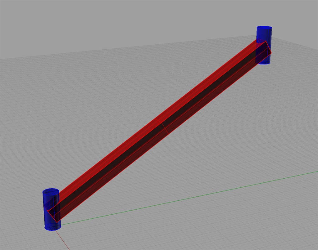
Two pivot blocks with the 1" tubing between them...
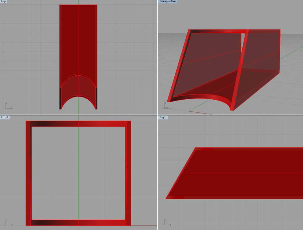
The result after "subtracting" the blocks to create the fish mouth with the right curves and angles...
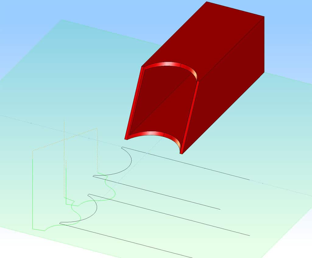
Imported into OneCNC XR4 and profile curves created for the upper and lower curve...
The g-codes are written on the assumption the 1" tubing sits in the vise with 1" protruding to the left of the jaws. 0, 0 is the vise's fixed top jaw, lower left corner. Cut the sides first, followed by the fish mouth curves.
G-Code to cut the Lower Arm Side
G-Code to cut the Lower Arm Fish Mouths
Base
Planning
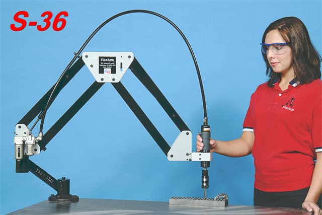
I have wanted a tapping arm since first reading about one. They're basically a parallelogram linkage and a little spindle to drive the tap. You grab it and go. These little beasts make it possible to tap a lot of holes in a hurry!
I envision just clamping it to a table in a corner somewhere.
Here are some typical commercial arms:
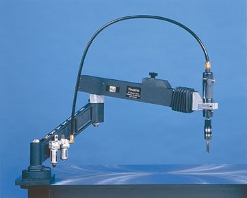
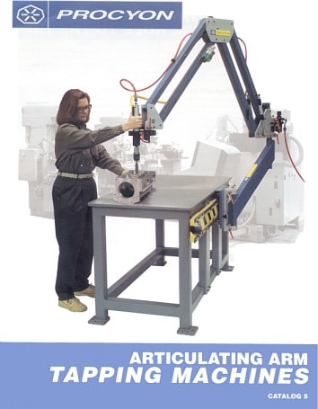
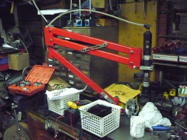
Here are a couple of views of one that John Stevenson made...
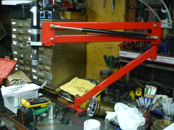
They look extremely handy and easy to use, and I've heard lots of good about them on Practical Machinist (the owner of the site seems to have invented the darned things!). I sure could have used one for my projects! The subject comes up on Practical Machinist usually because someone can't do rigid tapping in their CNC. Someone else usually suggests they buy a tapping arm rather than a new CNC. This is relevant to amateurs because Mach 3 doesn't support rigid tapping at the moment. The only bad news is that they seem to cost $1200 to $5000 and up. Wow!
The difficult part to source seems to be the spindle. Milacron (who built the Procyon arms) says he used Aro, Sioux, and Desouter straight shank air drills for his tapping arms. These are not cheap!
Then I saw something in an Enco catalog that gave me an idea. They just started selling Irwin Hanson tap adapters that fit a 3/8" ratchet. "Aha!" sez I. How about mating those guys up to the same Harbor Freight butterfly impact wrench I used to make my powered drawbar for the mill:
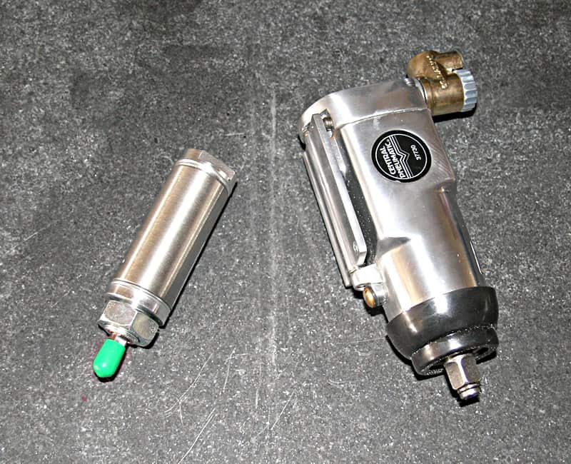
The cool thing about the impact wrench is that it has a paddle control making reverse convenient-exactly what's needed for tapping. There's also a little regulator on it so you can dial back the power, which also might be pretty handy to avoid breaking taps. I'm going to have to give the impact wrench a try, especially since they only sell for $19.99.
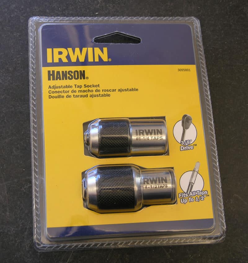
Here are the Enco adapters needed to mount taps on the impact wrench...
People worry these impact wrenches will break their taps. I haven't broken one yet, but I'm not sure I'd use a really tiny tap in the impact wrench.
To reduce the likelihood of breaking a tap, consider the following:
- Always use tapping fluid. I like tap magic and keep a can near the vise where most of my tapping occurs. I apply it liberally to the tap. Josh is spraying on some WD-40, which ought to work too.
- There is a built-in regulator on the wrench. Turn it down for smaller taps so you don't have full torque. These little wrenches don't have a ton of torque anyway. You can see in Josh's video his wrench really slowing down when it starts to cut.
- Use sharp taps. Josh is using a hardware store tap. They work, but there are better taps to be had. Do yourself a favor and get some form taps and some spiral taps for the hardware sizes you use most often in your shop. Wait until they go on sale and buy a few in each size. Be sure to get quality US made taps. Try them by hand first and you'll be amazed at how much less pressure is needed to tap a hole. The spiral taps extract the chips right up out of the hole very nicely. They designed so you don't have to keep reversing to break the chips, just keep on going. Form taps require a little more effort. They don't make a chip at all, they cold form the metal to produce a thread. I read on one manufacturer's site that they are 4x stronger (and therefore less likely to break) than cutting taps. I prefer form taps in aluminum, but there is a limit to how hard a material they will cut. Mild steel at best.
- Make sure your've got the right-sized hole! My G-Wizard Machinist's Calculator will figure that out for you based on what % thread you want to cut. If you're at all worried, choose a lower % of threads. The threads won't be as strong, but the bigger hole will make it easier to tap.
- It really matters to thread along the axis of the hole. That means the tap has to go in straight. There are lots of ways to ensure this, but a moment of inattention is all it takes to blow it. Once you have cut threads at an angle, it's too late. The smaller the tap, the more sensitive they will be. For real small taps, I use a piloted tap wrench in a drill press, a milling machine, or my lathe tailstock.
Of course a tapping arm means getting the tap aligned with the hole is easy, hence this project.
Another thought is that it would be easy to set this up for quick change since it is a socket system. Just by more of the Irwin Hanson adjustable tap sockets. They aren't cheap, but they aren't ridiculous either if you needed a quick change system to speed productivity.
I have tried the impact wrench with the tap adapters and they work great. Some have felt the hammering of the impact wrench is bad for the taps, but it's pretty feeble on this little wrench. I haven't see a problem in my own use.
Here is a drawing I made of the parallelogram linkage:
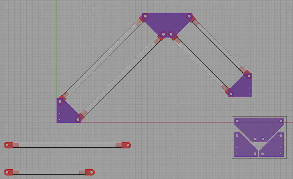
I'll need a swivel with clamp on the left end and some sort of clamp to hold the impact wrench on the right end. Counterweighting the arm is easy with gas springs connected diagonally across the parallels. I'll save this one until my CNC mill conversion is done, but it should be fun.
Be the first to know about updates at CNC Cookbook
Join our newsletter to get updates on what's next at CNC Cookbook.
