This page has my notes on model steam turbines. I haven't built one yet, but plan to someday.
Warning: Be careful with steam and especially steam turbine engines. Engines operate off energy and can generate significant forces. Steam explosions, bearing failures, and other maladies can be extremely hazardous!
A full on gas turbine is on my list as well, but model steam turbines are much simpler to build. I believe Bogstandard was to first to make me aware they even existed through his posts on the HMEM board, so I dedicate this page as a tribute to him and his wonderful "blingy" projects.
Steam Turbine Reference Material
The first modern steam turbine was invented in 1884 by Englishman Charles A. Parsons:
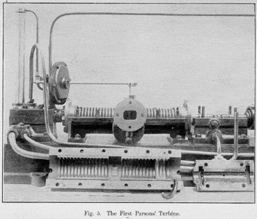
Parson's First Turbine...
There are two kinds of turbine, the impulse and reaction varieties:
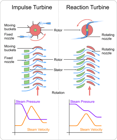
Two kinds of Steam Turbine. Most models will be "impulse" turbines...
Most models will be of the impulse variety due to the difficulties of producing the complex curves for a reaction turbine. Most commercial turbines are reaction. With an impulse turbine, steam velocity is everything, but there are tradeoffs. An air powered engine will generate the most velocity with a converging nozzle such as is described on the three rotor turbine below. However, steam is heated and can expand. In that case, providing more volume just before injection to the rotor blades converts as much heat as possible to velocity. So, a diverging nozzle (such as the "trumpet" nozzle on de Laval's turbine below) works better there.
Another issue is operating efficiency versus RPM. One of Parson's essential insights was to use successive stages that each expanded the steam a bit more to extract maximum energy from the steam expansion as well as designing a turbine that could run at a little slower rpm's than his predecessor's turbine Dr de Laval:

The de Laval turbine used trumpet shaped nozzles to extract most of the expansion energy from the steam, but it ran at velocities that were too high for the materials of the time except in very small applications. Might make for an interesting model though!
In fact, it is the use of multiple stages and more gradual steam expansion among the stages that leads to the greater efficiency at slower speeds of Parson's design. The different diameters at each stage are what allow for expansion on this 70,000 HP steam turbine rotor:
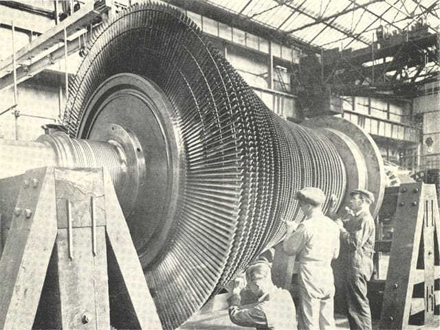
Increasing rotor diameters allow for steam expansion...
Here is a rotor from Parson's first turbine:


Straight bladed rotor must have been difficult to construct without CNC!
The blades were made of drawn brass. Each blade was fitted into a groove with a wedge, called a "distance" piece in the drawing. Here is some more on the labyrinth passages that connect each stage:

Guide blades redirect the steam direction for the next stage...
In modern times I'm sure the shape of the blades is carefully predicated on aerodynamics similar to those used to design airplane wings, but in Parson's time, no such understanding was available. His shapes were trial and error combined with intuition. Nevertheless, they were not bereft of sophisticated knowledge in other ways. For example, they determined that the optimal velocity of the blade was 1/2 to 3/4 of the velocity of the steam, hence the very high operating speeds of these turbines. Parson's first model ran at 18,000 rpm.

Isn't this a lovely curvaceous Parsons' turbine?
The model steam turbines I've seen are not Parson's turbines, they are impulse turbines, and hence the wind up to ridiculously high velocities. Enough to blow the bearings, so be careful! It would be fascinating to see a model Parsons, but the issue would be in the much increased complexity of many rotors for gradual expansion as well as complex shapes to machine on the rotor and stator blades. Certainly not impossible, as we see model gas turbines, just not easy.
Bogstandard's Single Rotor Impulse Steam Turbine
Bogstandard is (was, he may have left the forum) one of the real geniuses on the HMEM board. I learned a lot of things from him and always admired the fine craftsmanship of his model engines.
Here are photos from the first thread, a single rotor turbine that's really cool.
Raw materials, and machining the "buckets" on the rotor...

Parts. Note the steam ports on the housing. The first version had perspex on both sides...
I like the final version better. The back side is perspex. There is a little Swiss motor set up as a generator, and as the rpm increases, you see the LEDs light up one by one. The model is beautiful, and shows Bogstandard's trademark "bling" touches to make it more decorative.
Here is a video:
Bogstandard's Three Rotor Turbine
This one was made "on spec" for a model boater. Ultimately they concluded that the space available on the boat and the power characteristics made it impractical. These turbines don't make much power until they get over 10K rpm, and the more rpm you give them, the more prone to runaway they are. A 15 or 20:1 gear reduction would be needed as well as some form of speed governor to prevent the turbine from blowing up its bearings. Here is what it looks like when a model turbine blows:

Note the shredded housing as the rotor blew. Excercise care running these little engines to avoid exceeding their limits!
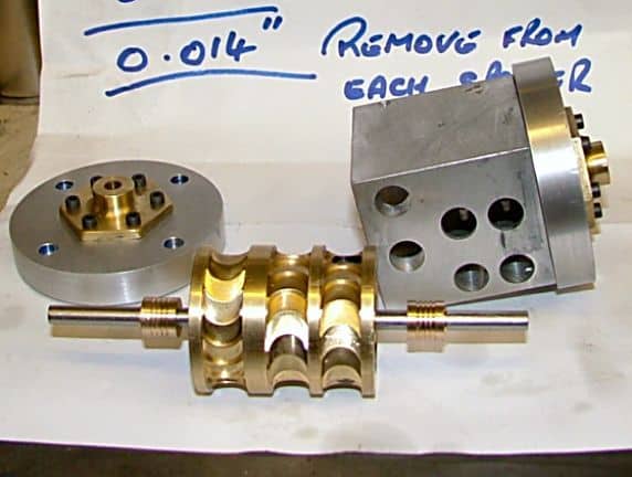
Getting back to the three rotor, here are some photos (many more on this one!):

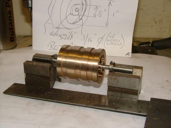
Sketch. Note how the leftmost rotor is a reversing rotor, so the "buckets" go the other way?


Turning the basic shape in phosphor bronze

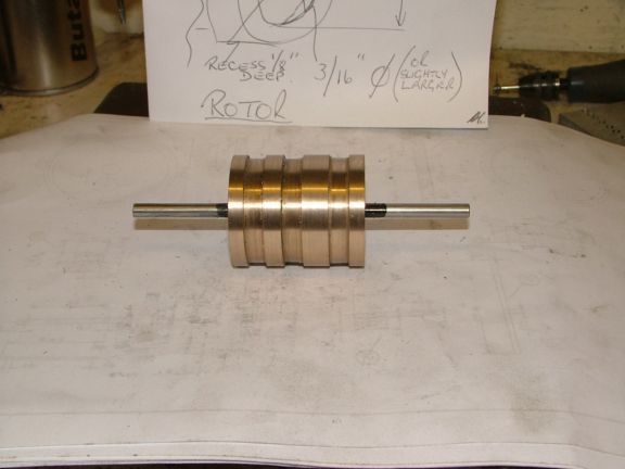
Rotor stack is drilled to lighten it...

Areas in green on the shaft are knurled to hold the shaft and rotor together...

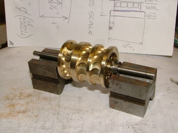
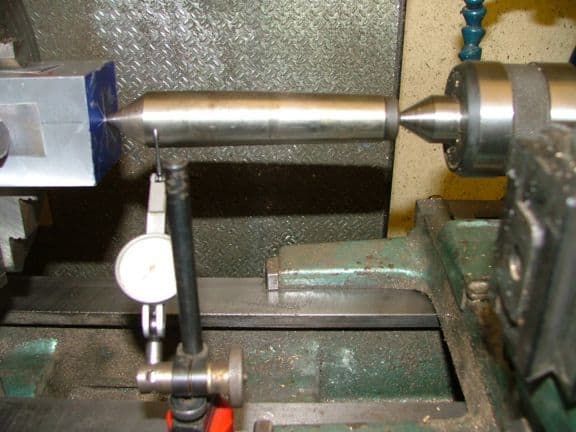
With the shaft press fitted, skim cuts are taken to ensure balance relative to the shaft...
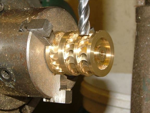
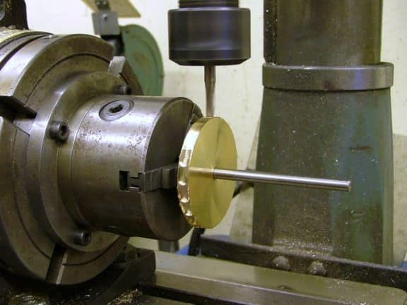
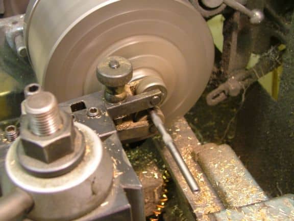
Now the buckets are being cut. It comes out looking quite exotic and beautiful, no?

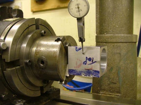
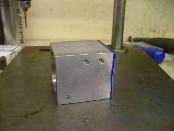
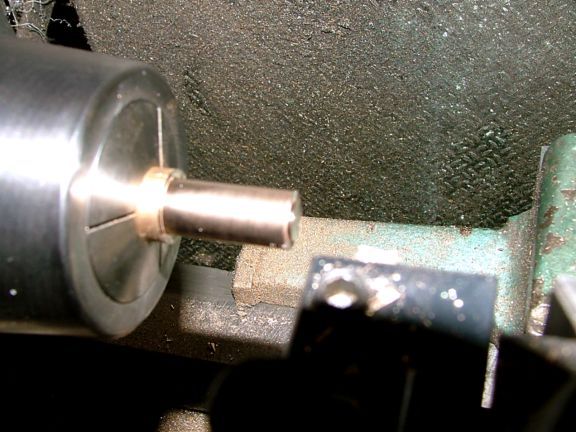
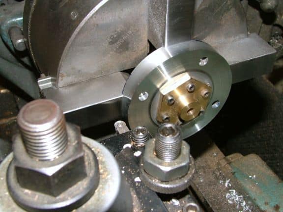
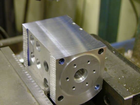
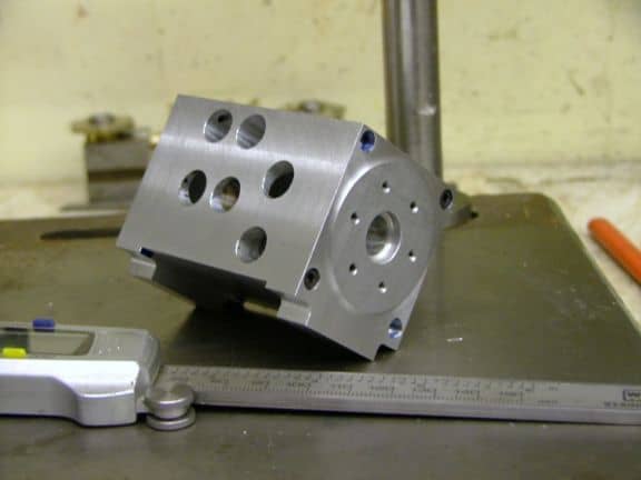
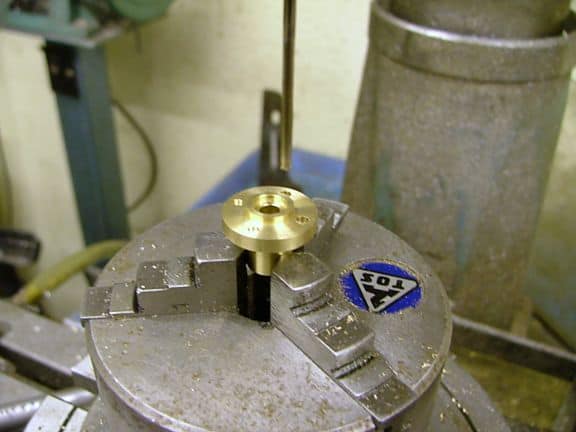
A squared block is placed in the lathe and aligned with the pump center...


First the big drill bits, then boring. Here is a trick if you don't keep your boring bars all in holders. Use a regular tool that is known to be set correctly to center to mark the workpiece...


Now line up your bar on that mark. Clever!


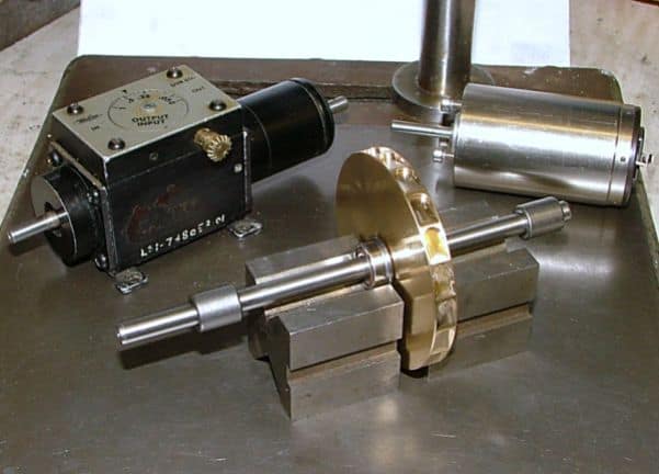
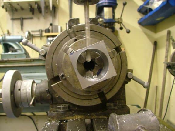
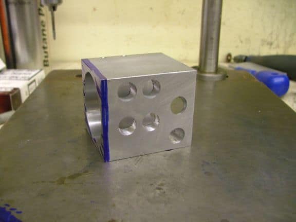
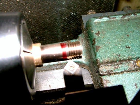
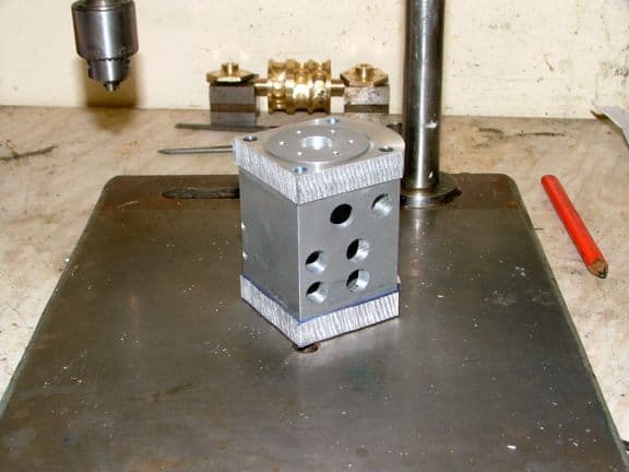
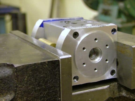
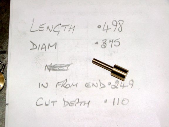
Rotor assembly fits just right after boring. Note the balancing holes on that rotor.
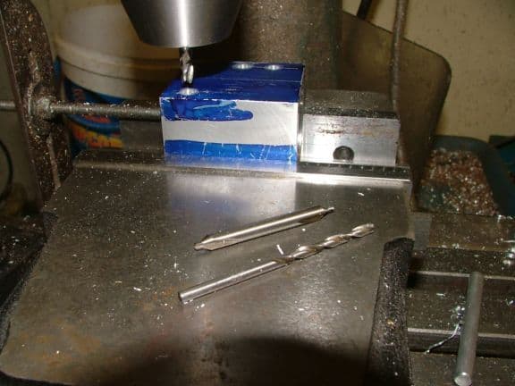
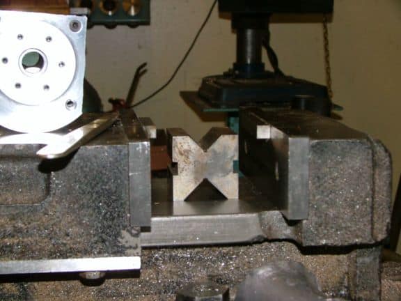
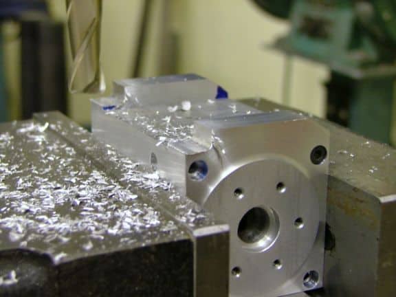
Nozzle holes are 1/8" followed by a 3/16" endmill to countersink an area for the connector to seat in. Next is the dividing head work. The face marked "top" was aligned along the rotational axis with a machinists square. The dial indicator is swept to be sure the axis is parallel to the mill's X-axis...
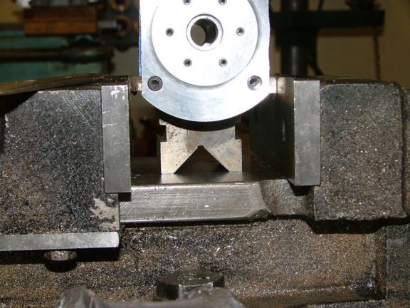
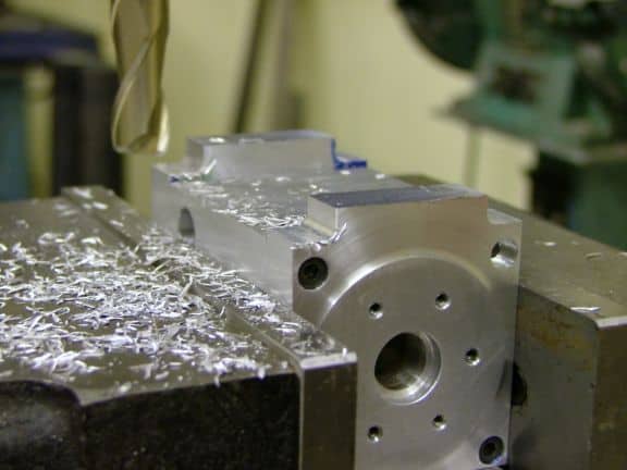
Now the mill is lined up on the original holes, the table is moved 3/8", and the head is rotated 20 degrees to achieve the correct tangential angle for the inlet port....
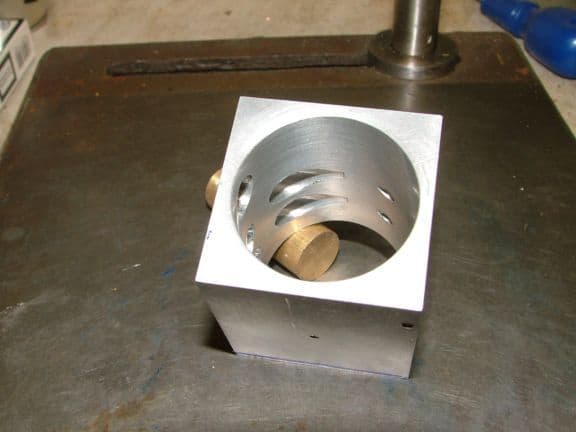
Here are the exhaust ports, which are much larger than the inlets to keep back pressure down...


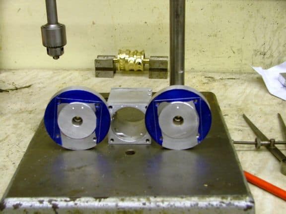
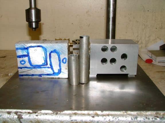
Next up are the endcaps. The housing is scribed to the endcap material and then a circle is drawn around with a dividers...

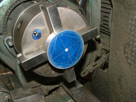
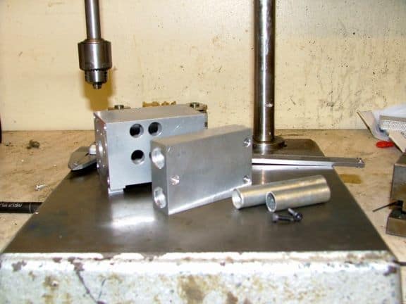
The endcaps are trimmed close to the outline on the bandsaw to save too much interrupted cutting on the lathe...


Watch this interesting trick to secure the workpiece. First, masking tape on the back side of the workpieces provides some friction with the chuck. Put a piece of stock in the jaws large enough so that when the jaws are tightened on it they are slightly smaller than the OD of the workpiece...


Now trap the workpiece against the chuck with a live center and you're ready to go! This is another reason Bog avoided a nasty interrupted cut: that masking tape only provides so much friction!


End pieces are close. About 1/8" too thick. Next up is machining the bearing pockets. This is done with softjaws on the 4-jaw chuck (this one is self-centering, an independent jaw wouldn't need the soft jaws) to make it as accurate as possible.


Bearing fit is good, so the workpiece is flipped and now a spigot is turned that will be a "wringing" fit to the bore...


The wringing fit is good and things are starting to take shape...


Next step are the bearing caps. Round insert tool makes a pretty radius...


Parted off and you can see how they look...


They need to be the same thickness, so the difference is measured on the surface plate...


And they're faced off in the collet chuck...


Bearing pockets cut...


Trial fit looks good. Here is the hardware to mount the end caps and bearing caps...


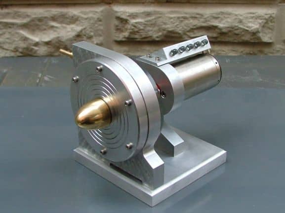
It's quite sophisticated looking, isn't it? I'd hate to try to carry one past airport security!

Just think: all that painstaking layout and setup would be trivial with a CNC...
![]()
![]()
These are the rotor spacers. These are set up with 0.002" clearance at either end to allow for thermal expansion...


Here is Bog's converging nozzle, which increases the velocity of air or steam entering the turbine. The actual nozzle is tiny!
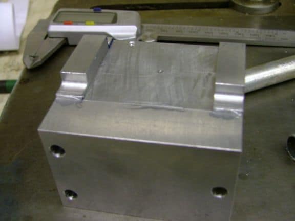
Time to modify the end plates some more. First they're marked off on the inside (where it won't show!). Then the outside gets a final facing to get rid of the old scribe marks and leave a nice blingey finish. This creates a nifty boss for appearance sake.
The Bogstandard wacks off the sides in the bandsaw. I keep thinking, why didn't he do more work in the mill and start out with a square piece, but I suppose he wanted the accuracy and finer finish of the lathe...
A nice flycut makes it look all better. In fact, it very nearly looks like a single block of metal there...
More cleanup, and a slightly radiused end mill result in mounting blocks...
Doesn't the result look sweet? Needs a shot of brake cleaner to get rid of the remaining blue in the holes...

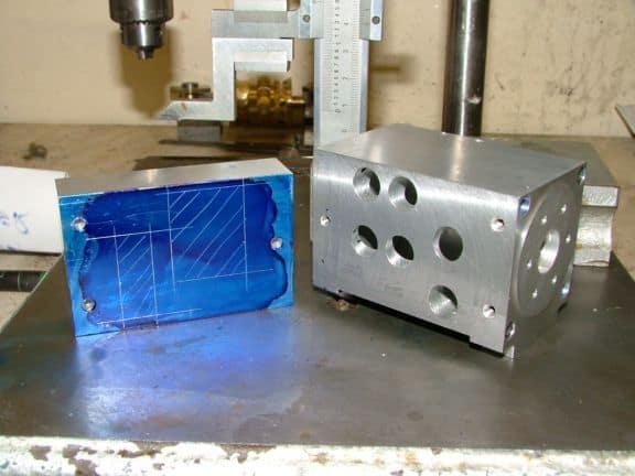
Now the exhaust manifold is a somewhat complex part...
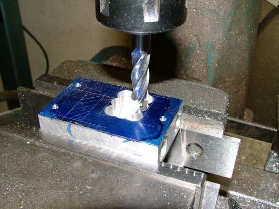
Plunge cuts for the pocket. Bog was at pains to machine without damaging the parallels. A better solution would be a set of softjaws with a step in the vise...
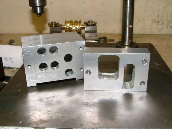

Woohoo, looking good with those big exhaust pipes! The blued piece is a brass plate: more bling!
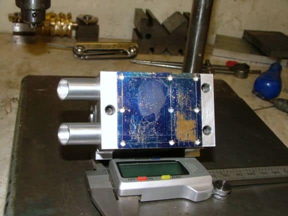

Holes are carefully drilled while the plate is held in place with double sided tape...


Ooooohhhhh, Shiiiiinnnnnnyyyyyy!


Sketches for the control valve...


Housing is turned to size, parted, and inserted in the collet block for edge finding...


3 Holes are drilled and then it's back to the lathe for boring. Hmmm, why not bore first? I guess it keeps burrs out of the bore...


The two end caps are being cut...


Last piccy shows how an o-ring groove will be cut...


Shaft fits and all looks well...


Checking the spool fit.


A precision drill blank rod held in place with a wooden wedge allows indication relative to the holes. A straight piece in the drill chuck locates the center hole to 0.002" under the lathe axis. I'd be using my Blake Coax for that, but I don't think Bog's mill has that much Z room...

Final dial in to clean up that 0.002 and the mounting holes can be drilled...


Spool valve is a sharp little piece of plumbing, no?

But useless without the spool!


Groove on either side to join passages....


A bit of dry fit up and it's time for the silver solder...

Comes out all blotchy, but it can be cleaned up quickly with a little Scotchbrite pad...


A marble makes an excellent control knob for the valve!


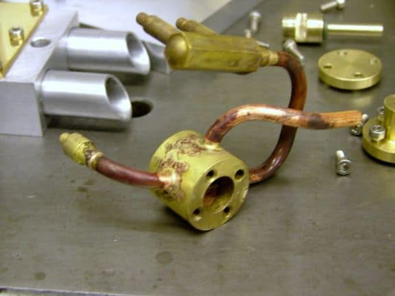
The finished steam turbine...
Watch it go!
Be the first to know about updates at CNC Cookbook
Join our newsletter to get updates on what's next at CNC Cookbook.