Key Takeaways
- Coaxial Indicators are an easy way to find the center of a circular feature-either a boss or a hole.
- They are accurate to maybe 0.001".
- If you need better, either use a DTI in a Zero Set or get a Haimer Centro.
- The longer the probe in the Coaxial Indicator, the less accurate it will be.
What is a Co-Ax Indicator?
Coaxial Indicators solve a common problem for machinist's that need to find the center of a circular feature-either a boss or a hole. There are a lot of ways to do this ranging from using a probe on a CNC to using one of the many tried-and-true methods that started out with manual machining. Our Complete Guide to Metrology goes over a bunch of methods.
The Blake Coaxial Indicator is one of those methods left over from the days of manual machining:
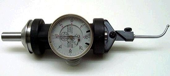
A Blake Coaxial Indicator...
How to Use a Coaxial Indicator
You stick one of these little goodies in the machine spindle, position it over the feature in question, start it spinning slowly, and adjust position until the indicator needle stops swinging. There's an offset arm not shown in the picture that keeps the indicator facing your way. Either hold the arm by hand or position it to wedge up against a part of the spindle head that doesn't move.
It usually takes more time to dig out your Co-ax Indicator and stick it in the machine spindle than it does to dial in the feature-they're very convenient, in other words. If there's a knock on them at all, it's about their accuracy.
Here is a video showing how to use your Blake Indicator:
A coaxial indicator set should include:
- The spring loaded co-ax indicator.
- A set of probes that range from straight to curved.
- An offset arm to keep the co-ax indicator facing your way as the machine spindle rotates.
Since the co-axial indicator is a centering indicator, it is a relative reading tool, not absolute. Therefore, no calibration is needed when we switch one of the probes for another.
A couple of tips when using a co-ax indicator:
- Keep the machine spindle to slow rotations. If you start the machine up at over a few hundred rpm with a co-ax indicator in the machine spindle, things will get ugly in a hurry.
- Make sure the probe is contacting the bore (or boss) all the way around an entire rotation.
- Start out having "eye balled" the tool to the center of rotation.
If you've taken a few moments to ensure those areas are covered, your co-ax indicator is ready to find the center of the bore or boss very quickly.
You can purchase a co-ax indicator off Amazon for prices ranging from about $109 for a knock-off to $439.99 for a "real" Blake Coaxial Indicator.
If you want to measure the feature much more accurately, most machinists reach for what is typically called a "Zero Set:"
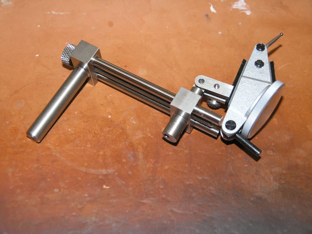
Zero Set-Style Indicator Holder...
The one I've got was made for me by a fellow from CNCZone called "Widgitmaster." It's a beautifully made piece of work with a fine screw adjustment for diameter. You stick it in the machine spindle and you can tell when you're centered on the feature because you rotate the DTI (Dial Test Indicator) and get no motion on the needle. With a nice Dial Test Indicator, you can measure very accurately indeed.
How Accurate is a Blake Coaxial Indicator?
But just how bad is a Blake Indicator compared to a Zero Set Dial Test Indicator rig like this? I tend to reach for my Dial Test Indicator when I want to position to a thousandth of an inch or better and use the Blake when it is less critical. Most of the Blake's error is due to what is called "cosine error." It's possible to have cosine error even with the Dial Test Indicator rig. It's a function of the angle the measuring needle has:
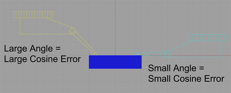
Keep as small an angle as possible on your Dial Test Indicator to minimize cosine error...
The cosine error is determined by the angle of the indicator tip to the surface being swept. No angle or a very small angle means no error. A large angle means a large cosine error. How large can the error get? Well, we can just take the cosine of some angles to see. Let’s try this for some real measurements. Let’s say we want to measure a distance of 0.010″. If our indicator tip angle is 60 degrees, we multiply the distance read off the indicator (0.010″) by the cosine of the angle:
cos( 60 ) * 0.010 = 0.005″
What that means is that with the tip at a 60 degree angle, when the indicator reads 0.010″, the real distance is 0.005″. That’s quite a bit of difference! Clearly we want to be sensitive to cosine error when taking such measurements.
Aside from paying attention to the angle of your measuring probe, there are some interesting ways that DTI manufacturers have worked to minimize cosine error. To learn more, click that prior link.
Note that the Blake Coaxial Indicator is a relative measuring device, so the effect of the cosine error is largely to reduce its sensitivity. If you wonder exactly how much error we're talking about here, we can use G-Wizard Calculator's Geometry module to figure it out pretty easily. This kind of problem comes up fairly often, and it's useful to be able to put real numbers to a solution. For example, it is a similar calculation to figure out how accurately a DRO scale must be aligned to a machine axis to give accurate measurements.
For this problem, let's first consider the mechanism of the Co-Axial Indicator. It basically uses a probe that swings a little lever as the machine spindle rotates. That lever raises or lowers a ring, and the ring is connected to an indicator. The lever on mine is about 1/2" long. So an important question to understand is how far must that lever move in order to move the indicator a particular distance, such as 0.001"?
Here is the geometry:
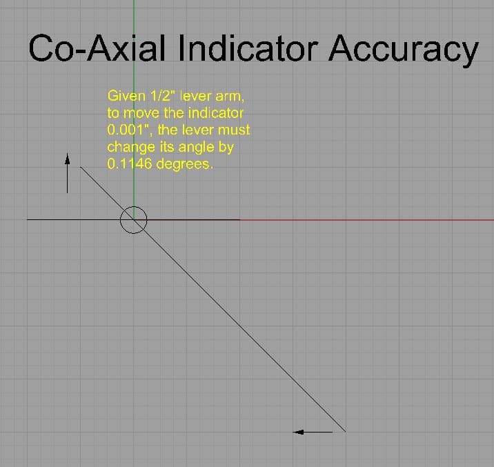
How far must the arm of a Co-ax Indicator move to make the indicator needle show 0.001" difference?
Now let's set up the calculation in G-Wizard that produced that 0.1146 degree figure:
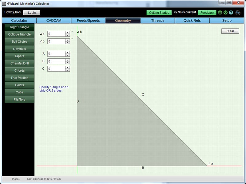
The Right Triangle Calculator from the G-Wizard Geometry tab...
This is an easy problem to set up. Referring to our CAD drawing, distance "A" is the 0.001" change on the indicator. Distance "B" is the offset of the probe tip.
Here is the result:
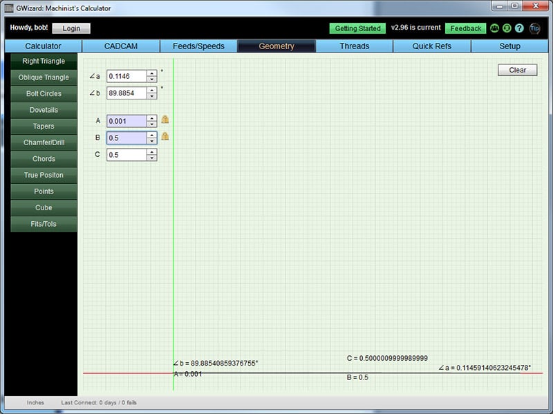
We use the Right Triangle Geometry Calculator to find the angle...
And sure enough we can see the angle is 0.1146 for that particular deflection.
Given that knowledge, its easy to use the same calculator to figure out for a given probe length, how much it deflects to generate the same angle (0.1146 degrees)?
Here is our result:
Co-Ax Indicator Reading
Probe Length
0.0010"
0.0005"
0.0001"
1"
0.0020
0.0010
0.0002
2
0.0040
0.0020
0.0004
3
0.0060
0.0030
0.0006
4
0.0080
0.0040
0.0008
5
0.0100
0.0050
0.0010
6
0.0120
0.0060
0.0012
Probe length on the left, indicator reading at top, boxes contain the level of cosine error...
We can see that the indicator's accuracy is based on how well you can read the dial. As mentioned above, the Blake's is calibrated to 0.0005" increments. You can certainly see that much motion of the needle, in fact it looks huge. Can you see the wiggle of 1/5 of a division? I certainly can, which would get me to the 0.0001" column. The longer the probe, the less accurate you will be, but I seldom use a probe longer than maybe 3", so the accuracy of the indicator is not too bad. Looks like a little over half a thousandth with the long probe.
You'll still do better with a Zero-Set and Dial Test Indicator, but if you can read your co-ax indicator well enough, they're more accurate than many believe. Consider them good to 0.001".
How Can I Tell if My Coaxial Indicator is Working Well?
Compare the measurement of your coax to that of a Zero Set-style DTI rig.
What's Better than a Coaxial Indicator?
The Haimer Centro is certainly rated to much better accuracy - 0.0001". But, they're not cheap-over $700 on Amazon. Still, if you need the accuracy and speed, they will be your Zero-Set DTI rig. Here's what one looks like:

Be the first to know about updates at CNC Cookbook
Join our newsletter to get updates on what's next at CNC Cookbook.