Machinists apply different types of indicators (such as the dial test or lever style, and the dial indicator commonly known as "plunger" style) throughout the day for a variety of tasks including tramming a vise. If you're serious about using one for accurate measurements, it's crucial to understand the concept of cosine error.
Consider the following diagram:
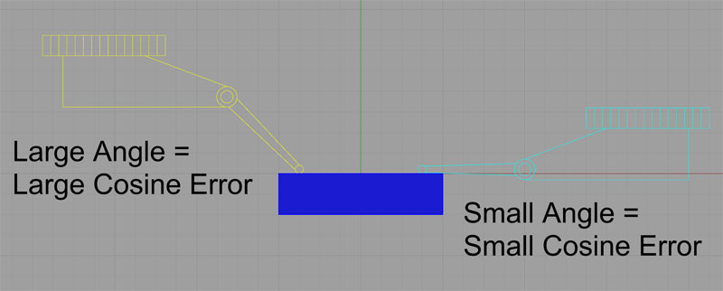
Cosine Error is determined by the angle of the indicator tip to the surface being swept.
The cosine error is determined by the angle of the indicator tip to the surface being swept. No or a very small angle means no error. A large angle means a large cosine error. How large can the error get? Well, we can just take the cosine of some angles to see. Let's try this for some real measurements. Let's say we want to measure a distance of 0.010". If our indicator tip angle is 60 degrees, we multiple the distance read off the indicator (0.010") by the cosine of the angle:
cos( 60 ) * 0.010 = 0.005"
What that means is that with the tip at a 60 degree angle, when the indicator reads 0.010", the real distance is 0.005". That's quite a bit of difference!
We've talked about dial test indicators (lever type) so far. The angle is the angle of the tip arm to the flat surface being swept, or the angle to a tangent to a curved surface being swept. Cosine angle also affects dial indicators (plunger type). The difference is in how we measure the angle. With a dial indicator, you want the plunger to be perpendicular to the surface being measured. So, the angle for cosine error calculations will be the difference between that ideal perpendicular angle and the real angle the indicator is at.
Unless you're really messing with some fidgety measurements, you probably won't make many calculations to adjust for cosine error. But what you should do is be aware of what it is and try to always arrange to use your indicator so that cosine error is minimized. It's a basic technique thing.
I saw in an article in MMSOnline that there are indicator tips that are shaped like an involute. Involutes are interesting curves that are also used for gear design. The thing to note is that up to a cosine error angle of as much as 20 degrees, the shape of the involute tip makes it self-correcting for cosine error. The tip is said to be football shaped. I'm curious whether indicators with such tips are available "off the shelf". Mitutoyo says they're a custom item in their dial indicator pamphlet. BTW, very cool little 3 page pamphlet with a cutway of a dial indicator.
Another thing is that some indicators are calibrated to work with zero error at an angle other than zero. My favorite dial test indicators are Interapids, and they are calibrated to be spot on at 12 degrees according to Long Island Indicator. What a great idea as it seems like the arm is always at an angle using a DTI. You can see why from my illustration, things start getting in the way if you truly have to sweep at zero degrees.
If you haven't used an Interapid, you're missing out.
Be the first to know about updates at CNC Cookbook
Join our newsletter to get updates on what's next at CNC Cookbook.