Free GD&T Calculator [ + Much More ]
GD&T Perpendicularity Symbol
Definition of Perpendicularity
In GD&T, Perpendicularity can refer to either Surface Perpendicularity or Axis Perpendicularity.
Surface Perpendicularity
Surface Perpendicularity is a tolerance that controls Perpendicularity between two surfaces aligned at 90 degrees to each other. It is controlled by two parallel planes acting as a tolerance zone. Perpendicularity can also reference a 2D line, but it is more commonly used to describe the orientation of one surface plane perpendicular to another datum plane.
Axis Perpendicularity
Axis Perpendicularity is a tolerance that controls how Perpendicular a specific axis needs to be to a datum. In other words, it establishes a cylindrical boundary around the axis. It is controlled by a cylindrical tolerance zone around a theoretical perfectly parallel axis which is directly perpendicular to the datum feature.
Axis Perpendicularity can be applied to a positive feature such as a pin or boss, or to a negative feature such as a hole.
If the Perpendicularity symbol is used for a hole or a pin, it is likely referring to the Axis Perpendicularity of the associated feature.
In both cases, perpendicularity is always relative to a datum specified in the feature control frame.
When Axis Perpendicularity is called out it should be used with maximum material condition to enable easy gauging of the part.
GD&T Perpendicularity of a Hole
Let's pause for a minute and talk about GD&T Perpendicularity of a Hole. As mentioned above, we'll be talking about an axis perpendicularity tolerance. We will need a datum plane called out in the feature control frame that the axis is to be perpendicular to. That's about all there is to it!
Perpendicularity Callout on Drawings
The surface and axis form of perpendicularity is very common. You will see it on many mechanical drawings.
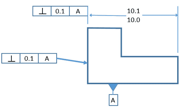
Surface Perpendicularity Callout...
The Surface Perpendicularity Callout above shows the two ways Perpendicularity can be called out either as part of a dimension or directly associated with a feature. In both cases, we must also associate a datum "A".
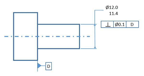
Axis Perpendicularity callout...
For the Axis Perpendicularity callout, we specify not just the perpendicularity, but the diameter of the tolerance zone's idealized cylinder. So, the axis of that cylinder is perpendicular to the datum "D", and the cylinder has a diameter of 0.1.
Perpendicularity Tolerance Zone
The Tolerance Zone for a Surface Perpendicularity Tolerance looks like two planes that are perpendicular to the datum and separated by the tolerance. Every point on the controlled surface must fall between the planes. Picture it like this with the dotted red lines being the two planes and the reference datum they're perpendicular to:
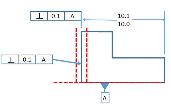
Tolerance Zone for Surface Perpendicularity shown in dotted red...
The Tolerance Zone for Axis Perpendicularity is an ideal cylinder surrounding the axis. No part of the axis can protrude from the cylinder.
Gaging and Measurement of Perpendicularity
Refer to the diagrams above and you can tell pretty quickly how to sweep to measure a Perpendicularity Tolerance. For the Surface Perpendicularity example, sweep an indicator along the surface perpendicular to a surface plate that is serving as the datum, for example. This is a function that a coordinate measuring machine is well suited to.
We can construct a functional gage for axis perpendicularity given that we basically just need a cylinder (or hole) gage of the dimensions of the tolerance zone's idealized cylinder. A standard pin gauge may work well. When a functional gage is used, any difference the actual feature size is from the maximum material condition would be a bonus tolerance. The goal of a maximum material condition callout is to ensure that when the part is in its worst tolerances, the orientation and size of the hole/pin will always assemble together. This means that if you make a pin smaller, you make more bonus tolerance for yourself. This bonus tolerance can be added to the GD&T tolerance and would widen the perpendicularity tolerance.
GD&T Table of Contents GD&T Symbols
Be the first to know about updates at CNC Cookbook
Join our newsletter to get updates on what's next at CNC Cookbook.