What is a Feature Control Frame?
A Feature Control Frame describes the conditions and tolerances of a geometric control on a part’s feature. A feature control frame contains four pieces of information:
- GD&T symbol or control symbol
- Tolerance zone type and dimensions
- Tolerance zone modifiers
- Datum references if the GD&T symbol requires them
Each Feature Control Frame will typically (it is optional) have a leader arrow pointing to the feature it describes.
Free GD&T Calculator [ + Much More ]
Consider the Feature Control Frame in the drawing below:
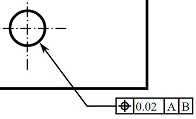
A Feature Control Frame…
The Leader Arrow points to the hole feature. It has a Geometric Symbol, in this case, a Position Symbol. Given that this is a round hole, the tolerance could be a diameter, in which case we’d have a diameter symbol ahead of the tolerance. Instead, we just have a tolerance value, so this is a positional tolerance for the center of the hole. We could follow the tolerance with a Tolerance Modifier. The “A” and “B” are the primary and secondary datum. If we look to the original drawing (top of page) we can see that these tell us where to measure the hole’s center from. In this case, “A” denotes the top edge of the part and “B” denotes the left edge.
Placement of Feature Control Frames
Any shape or surface may have an associated feature control frame. Typically, the frame appears below or adjacent to the feature with a leader arrow identifying the particular feature.
Parts of the Feature Control Frame
A feature control frame has the following parts:
- Leader arrow designating what feature this frame is associated with
- GD&T symbol or control symbol
- Diameter symbol if the geometric control has a diametrical tolerance
- Tolerance zone shape and dimensions
- Tolerance zone modifiers such as material conditions modifiers, projects, and so on.
- Primary, Secondary, and Tertiary Datum references if required by the GD&T symbol.
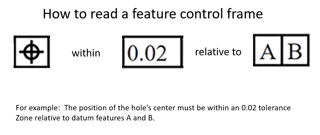
Reading the Feature Control Frame
Think of the Feature Control Frame as forming a sentence when you read it. Move left to right and call out each part in words:
Composite Feature Control Frame
In cases where you must provide two tolerance zone frameworks, you will use a Composite Feature Control Frame. That just means using two rows instead of one.
Multiple Single Segment Control Frame
Multiple Single Segment Control Frames are much like Composite Feature Control Frames except the tolerance zones are completely independent.
Next Article: GD&T Maximum Material Condition
GD&T Table of Contents GD&T Symbols
Be the first to know about updates at CNC Cookbook
Join our newsletter to get updates on what's next at CNC Cookbook.