Free GD&T Calculator [ + Much More ]
GD&T Angularity Symbol
Definition of Angularity
In GD&T the Angularity symbol is used to reference how one feature is oriented to another at a referenced angle. For example, it could reference the orientation of a surface plane relative to a datum plane in a 3D tolerance zone, or it could referene the relationship of a 2D line to another 2D element.
Note that Angularity only indirectly controls the tolerance for the actual angle, which will normally be directly controlled by a plus/minus tolerance. Angularity will indirectly control the angle tolerance because its Tolerance Zone does limit the freedom of where the features can lie.
Angularity vs Plus/Minus Tolerancing an Angle
So why have Angularity versus plus/minus tolerancing of an angle?
GD&T is all about making sure parts fit, and the tolerance zone of Angularity comes closer to that ideal than simple plus/minus tolerancing of the angle. An angle can only refer to two lines. But the Tolerance Zone of Angularity can refer to surfaces. So, for example, it could control an entire plane rather than just a line.
If we think about just trying to use angles, they're not enough to control a whole plane. Therefore, Angularity is more concise.
Consider the Tolerance Zone for Angularity of two surfaces. It consists of two planes parallel to one of the surfaces that lie at an angle to the Datum. The two planes are separated by the Angularity tolerance. Every point on the surface must be inside the two planes.
Angularity for a circular hole applies to the hole's axis. In this case, the Tolerance Zone is a cylinder around the axis.
Gaging and Measurement of Angularity
Angularity is typically measured by sweeping an indicator, probe, or other sensor over the surface to ensure all points lie within the parallel planes.
Given that the surfaces are at angles, some fair bit of effort is needed to construct an inspection fixture for angularity. Sine Plates and the like are often called for so the surface being swept is parallel to a surface plate, for example.
Angularity Callouts on Drawings
Use of Angularity in a drawing...
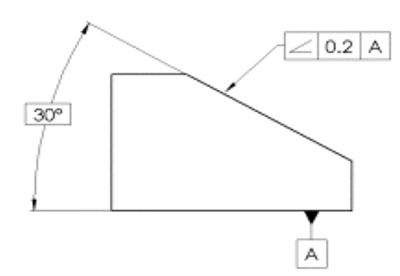
Use of Angularity in a drawing is straightforward. Simply callout the Angularity allowance in a feature control frame with an arrow leader designating the surface being controlled. Be sure to include the Datum for the Angularity.
In the example above, there are three callouts:
- The 30 degree angle. Note that we don't bother to include plus/minus tolerancing on the angle.
- The Angularity Feature Control Block which says the surface must fall within two parallel planes that are 0.2 apart, and the A Datum is referenced.
- The A Datum is identified as the bottom surface..
GD&T Table of Contents GD&T Symbols
Be the first to know about updates at CNC Cookbook
Join our newsletter to get updates on what's next at CNC Cookbook.