Free GD&T Calculator [ + Much More ]
GD&T Circularity / Roundness Symbol
Definition of Circularity (Roundness)
In GD&T, Circularity describes how close an object should be to a true circle. It is also sometimes called Roundness. Examples of features that might have Circularity controls would be cylinders, spheres, and cones. For moving parts, circularity is often used to help ensure the parts move smoothly and wear evenly. For example, it might common be used to control the roundness of a shaft.
Since we apply circularity to a particular surface, it does not need to be related to a datum. Circularity is the 2D version of Cylindricity.
Circularity Callout on Drawings
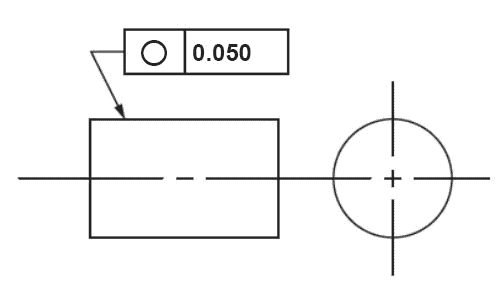
Circularity callout...
The Circularity callout points the arrow to the surface and gives the tolerance. The Circularity Feature Control Block might also be applied to the Diameter dimension of a circular feature.
Circularity Tolerance Zone
The Tolerance Zone for Circularity is two concentric circles, one inside the other. The circles lie on a plane that is perpendicular to the axis of the circular feature. All the points on the circular surface being controlled must fall between the inner and outer circles that make up the Circularity Tolerance Zone.
In the drawing callout above, every point on the cylinder must be within the two concentric circles and they differ in diameter by 0.050".
Gaging and Measurement of Circularity
Gaging Circularity is straightforward. Constrain the part so it can be rotated around the central axis and measure the deviation of the surface with a height gage or other measuring device.
GD&T Table of Contents GD&T Symbols
Be the first to know about updates at CNC Cookbook
Join our newsletter to get updates on what's next at CNC Cookbook.