Whenever we need to affix a part to a shaft, such as a gear or pulley, keyways, keys, and keyseat work or woodruff work comes into play. So, let's begin by getting our terminology straight.
A Keyway is a slot of some kind that is used to align the part on a shaft and prevent the part slipping as the shaft rotates. A Key goes into the Keyway to lock things up. Another name for a Keyway is a Keyseat, since the Key is seated in the Keyseat. When a specialized cutter is used to cut the Keyseat, it's a Keyseat Cutter. A Woodruff Cutter is a Keyseat Cutter.
There are several kinds of Keys in common use.
Parallel Keyways & Keys
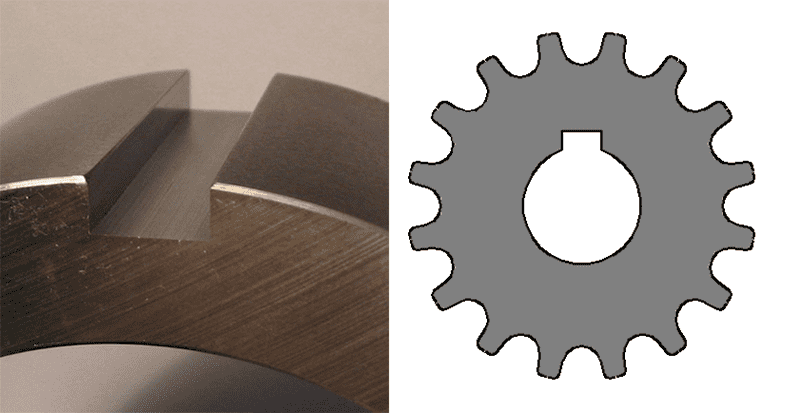
Parallel keys are the simplest, and involve a slot that goes all the way through at least the part with the shortest axial mating length (i.e. the gear or the pulley. Cutting a parallel key is straightforward-just use an endmill and treat it as cutting any other slot. Alternatively, you could use a Keyseat Cutter such as a Woodruff Cutter.
Key stock is available pre-cut in standard inch and metric sizes, and the ends may either be squared or rounded.
Parallel Inch Key Sizes
Shaft Diameter
Width
Keyway (Shaft
Keyway (Hub)
Radius r
Height
Width
Height
Width
height
Over
To/Inc
W & T
Min
Max
Max
Min
Min
Max
Min
Max
1/4
1/2
1/8
0.124
0.125
0.072
0.078
0.125
0.126
0.06
0.066
0.01
1/2
3/4
3/16
0.187
0.188
0.107
0.113
0.188
0.189
0.088
0.094
0.01
3/4
1
1/4
0.249
0.25
0.142
0.148
0.25
0.251
0.115
0.121
0.01
1
1 1/4
5/16
0.311
0.312
0.177
0.183
0.312
0.313
0.142
0.148
0.01
1 1/4
1 1/2
3/8
0.374
0.375
0.213
0.219
0.375
0.376
0.169
0.175
0.01
1 1/2
1 3/4
7/16
0.437
0.438
0.248
0.254
0.438
0.439
0.197
0.203
0.02
1 3/4
2
1/2
0.499
0.5
0.283
0.289
0.5
0.501
0.224
0.23
0.02
2
2 1/2
5/8
0.624
0.625
0.354
0.36
0.625
0.626
0.278
0.284
0.02
2 1/2
3
3/4
0.749
0.75
0.424
0.43
0.75
0.751
0.333
0.339
0.02
3
3 1/2
7/8
0.874
0.875
0.495
0.501
0.875
0.876
0.387
0.393
0.062
3 1/2
4
1
0.999
1
0.566
0.572
1
1.001
0.442
0.448
0.062
4
5
1 1/4
1.248
1.25
0.707
0.713
1.25
1.252
0.551
0.557
0.062
5
6
1 1/2
1.498
1.5
0.848
0.854
1.5
1.502
0.661
0.667
0.062
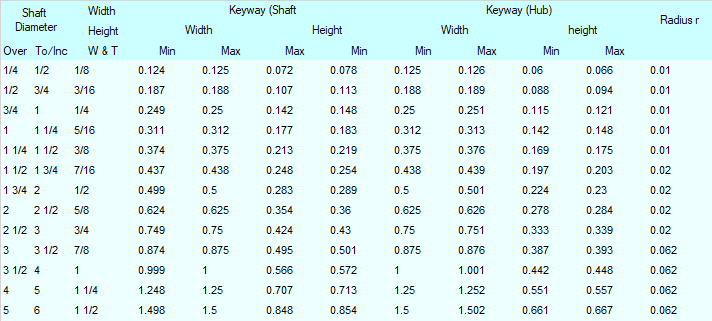
Per BS 46 Part 1 : 1958 Keys and keyways and taper pins. Specification. Keys and keyways.
Parallel Metric Key Sizes
Nominal Diameter
Key
KeyWay
d
b x h width x thck
Width b
Depth
Radius r
Nom
Tolerance Class
Shaft t1
Hub t2
Over
Incl
Free
Normal
Close/Int
Shaft
Hub
Shaft
Hub
Shaft/Hub
Nom
Tol
Nom
Tol
Max
min
H9
D10
N9
Js9
P9
6
8
2×2
2
+0,025
+0,06
- 0,004
+0,012
- 0,006
1,2
+0,1
1,0
+0,1
0,16
0,08
8
10
3×3
3
0
+0,02
- 0,029
- 0,012
- 0,031
1,8
0
1,4
0
0,16
0,08
10
12
4×4
4
+0,03
+0,078
0
+0,015
- 0,012
2,5
1,8
0,16
0,08
12
17
5×5
5
0
+0,030
- 0,030
- 0,015
- 0,042
3,0
2,3
0,25
0,16
17
22
6×6
6
3,5
2,8
0,25
0,16
22
30
8×7
8
+0,036
+0,098
0
+0,018
- 0,015
4,0
+0,2
3,3
+0,2
0,25
0,16
30
38
10×8
10
0
+0,040
- 0,036
- 0,018
- 0,051
5,0
0
3,3
0
0,40
0,25
38
44
12×8
12
+0,043
+0,12
0
+0,021
- 0,018
5,0
+0,2
3,3
+0,2
0,40
0,25
44
50
14×9
14
0
+0,050
- 0,043
- 0,021
- 0,061
5,5
0
3,8
0
0,40
0,25
50
58
16×10
16
6,0
4,3
0,40
0,25
58
65
18×11
18
7,0
4,4
0,40
0,25
65
75
20×12
20
+0,052
+0,149
0
+0,026
- 0,022
7,5
4,9
0,60
0,40
75
85
22×14
22
0
+0,065
- 0,052
- 0,026
- 0,074
9,0
5,4
0,60
0,40
85
95
25×14
25
9,0
5,4
0,60
0,40
95
110
28×16
28
10,0
6,4
0,60
0,40
110
130
32×18
32
+0,062
+0,18
0
+0,031
- 0,026
11,0
7,4
0,6
0,4
130
150
36×20
36
0
+0,080
- 0,062
- 0,031
- 0,088
12,0
+0,3
8,4
+0,3
1,0
0,7
150
170
40×22
40
13,0
0
9,4
0
1,0
0,7
170
200
45×25
45
15,0
10,4
1,0
0,7
200
230
50×28
50
17,0
11,4
1,0
0,7
230
260
56×32
56
+0,074
+0,220
0
+0,037
- 0,032
20,0
12,4
1,6
1,2
260
290
63×32
63
0
0,100
- 0,074
- 0,037
- 0,106
20,0
12,4
1,6
1,2
290
330
70×36
70
22,0
14,4
1,6
1,2
330
380
80×40
80
25,0
15,4
2,5
2,0
380
440
90×45
90
+0,087
+0,260
0
+0,043
- 0,037
28,0
17,4
2,5
2,0
440
500
100×50
100
0
0,120
- 0,087
- 0,043
- 0,124
31,0
20
2,5
2,0
Per BS 4235-1:1972: Specification for metric keys and keyways - Parallel and taper keys.
Woodruff Keyways & Keys
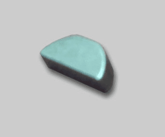
Woodruff Keys are an alternative to Parallel Keys. They are semi-circular, and fit into a Keyway shaped as a circular-segment in the shaft and a rectangular slot in the mating part. The semi-circular slot is cut by plunging a Woodruff Cutter (the correct Keyseat Cutter for this style Keyway) into the workpiece.
The advantages of Woodruff Keys over Parallel Keys are:
- They eliminate the milling near shaft shoulders which reduces stress concentrations and makes it easier to maintain circularity constraints.
- They are therefore better suited to higher speed operation of the rotating shaft.
- The key typically has a more exact fit which reduces play and improves the reliability of the key.
- A Woodruff key may be easier to remove with a hammer blow since the circular profile will push the key out of the slot. A Parallel key requires the key to be pushed axially a longer distance.
Woodruff Keys were developed in 1888 by W.N. Woodruff of Connecticut, USA.

Woodruff keys may be full radius or flat bottom, but the keyseat will always be radiused by the Keyseat Cutter / Woodruff Cutter. A flat bottom Woodruff Key has part of the radius shaved right at the bottom:
Woodruff Key Dimensions (Inch)
Like Parallel Keys, Woodruff Keys come in standard sizes:
KEY NUMBER
KEY DIMENSIONS
SHAFT DIAMETER
HEIGHT OF KEY ABOVE SHAFT
DEPTH OF KEYWAY
DIAMETER
WIDTH
MINIMUM
MAXIMUM
204
1/2
1/16
5/16
3/8
0.0312
0.1718
304
1/2
3/32
5/16
1/2
0.0469
0.1 561
404
1/2
1/8
9/16
3/4
0.0625
0.1405
405
5/8
1/8
9/16
3/4
0.0625
0.1875
505
5/8
5/32
13/16
15/16
0.0781
0.1719
406
3/4
1/8
11/16
3/4
0.0625
0.2505
606
3/4
3/16
1
1 1/8
0.0937
0.2193
507
7/8
5/32
1 1/8
15/16
0.0781
0.2969
807
7/8
1/4
1 5/16
1 1/8
0.125
0.25
608
1
5/16
1
1 7/16
0.0937
0.3443
1008
1
5/16
1 1/16
1 5/8
0.1562
0.2818
609
1 1/8
5/16
1 1/16
1 7/16
0.0937
0.3903
810
1 1/4
1/4
1 1/4
1 3/4
0.125
0.422
1210
1 1/4
3/8
1 1/2
1 7/8
0.1875
0.3595
1011
1 3/8
1/2
1 13/16
2
0.1562
0.4378
Woodruff Key Dimensions (Metric)
w x h1 x D......
Width b
Depth
Radius R
Nom
Tolerance Class
Shaft t1
Hub t2
Normal
Close
Shaft
Hub
Shaft & Hub P6
Nom
Tol
Nom
Tol
Max
min
N9
Js9
1,0 x 1,4 x 4
1
- 0,004
+0,012
- 0,006
1,0
+0,1
0,6
+0,1
0,16
0,08
1,5 x 2,6 x 7
1,5
- 0,029
- 0,012
- 0,0031
2,0
0
0,8
0
0,16
0,08
2,0 x 2,6 x 7
2,0
1,8
1,0
0,16
0,08
2,0 x 3,7 x 10
2,0
2,9
1,0
0,16
0,08
2,5 x 3,7 x 10
2,5
2,7
1,2
0,16
0,08
3,0 x 5,0 x 13
3,0
3,8
+0,2
1,4
0,16
0,08
3,0 x 6,5 x 16
3,0
5,3
0
1,4
0,16
0,08
4,0 x 6,5 x 16
4,0
0
+0,015
- 0,012
5,0
1,8
0,25
0,16
4,0 x 7,5 x 19
4,0
- 0,030
- 0,015
- 0,042
6,0
1,8
0,25
0,16
5,0 x 6,5 x 16
5,0
4,5
2,3
0,25
0,16
5,0 x 7,5 x 19
5,0
5,5
2,3
0,25
0,16
5,0 x 9.0 x 22
5,0
7,0
+0,3
2,3
0,25
0,16
6,0 x 9,0 x 22
6,0
6,5
0
2,8
0,25
0,16
6,0 x 11,0 x 28
6,0
7,5
2,8
+0,2
0,25
0,16
8,0 x 11,0 x 28
8,0
0
+0,018
+0,015
8,0
3,3
0
0,40
0,25
10,0 x 13,0 x 32
10,0
- 0.036
- 0.018
- 0.051
10,0
3,3
0,4
0,25
Keyseat Cutters (aka Woodruff Cutters or Woodruff Key Cutters)
Woodruff Keys take a special Keyseat Cutter called a Woodruff Cutter. It's basically a small saw. They look like this:
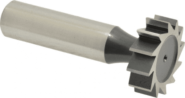
Woodruff Cutters are a subset of the broader category of Slotting Cutters.
A Woodruff Cutter may be constructed from HSS or Solid Carbide. The solid carbide versions are capable of both higher material removal rates (e.g. shorter cycle times) and longer tool life, so they are often preferred for production work.
Woodruff Cutter & Keyseat Cutter Feeds and Speeds Calculator
Woodruff and Keyseat Cutters behave like Saws. Learn a lot more tips and deeper feeds and speeds info from our article on Slitting Saw Feeds and Speeds, Tips, and Techniques.
Our G-Wizard Feeds and Speeds Calculator has special support for Woodruff Cutters & Keyseat Cutters. To set up the Woodruff Cutter cut in the Calculator, we go left to right, top to bottom:
1. Select the Machine
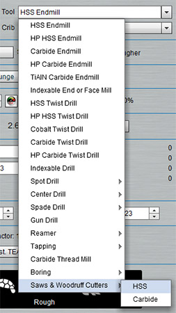
2. Select the Material
3. Select the Woodruff Cutter from the tool menu (Note: Keyseat cutters are referred to as Woodruff cutters for feeds and speeds):
4. Select what material the tool is made from, either HSS or Solid Carbide, and what coating it has (if any). A good coating can provide some added lubricity to make the material cut more easily.
5. Enter your cutter’s diameter and number of teeth.
6. Enter your cutter’s thickness
7. You can optionally add information such as shank length, neck diameter, and overall length. This information won't affect feeds and speeds but will make your tool tables more complete.
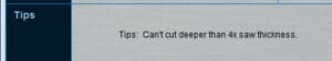
8. Enter the Depth of Cut. This is the total depth of the keyseat. G-Wizard should remind you to keep cut depth less than 4x saw thickness:
Note that in the case of a Woodruff key, you want to choose a saw diameter (cut diameter) that is equal to your woodruff key's diameter.
Here is the finished result:
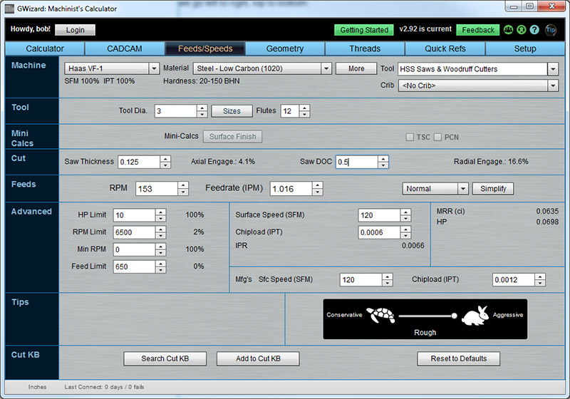
Typical setup to find Feeds and Speeds for a Slitting Saw…
If you’re not a registered G-Wizard user and you’d like to try our free 30-day trial, check it out on this page.
Sneaky Stuff: What Else Can a Woodruff Cutter Do?
They can be quit useful for making undercuts in a workpiece.
Be the first to know about updates at CNC Cookbook
Join our newsletter to get updates on what's next at CNC Cookbook.