Tool Data is very important to CNC. The controller has to be told which tool to load from the changer, and what the tool length and diameter wear offsets are in order to know exactly where the tip of each tool is located.
In addition, there is a lot of other information that makes it far easier for machinist's to deal with and understand their g-code programs-things like human readable names instead of just T numbers.
Lastly, there is the task of coordinating what the design office thinks the tools are when they're running their CAM program, and what the shop floor thinks the tools are when it comes time to run the job.
Facilitating these tasks is the job of the Tool Data Management features in G-Wizard Editor.
For a good grounding in Tool Offsets and Tool Data Management, try the two-part CNCCookbook series here. The first part is basic, and the second part is more advanced. This page is all about how to do some of the things being talked about within GWE.
GWE's TDM features are primarily associated with 3 views-the "Tools" View, the "Tool Crib", and the "Tool Comp" macro variables. Let's consider each and then talk about how they work together.
Tools View
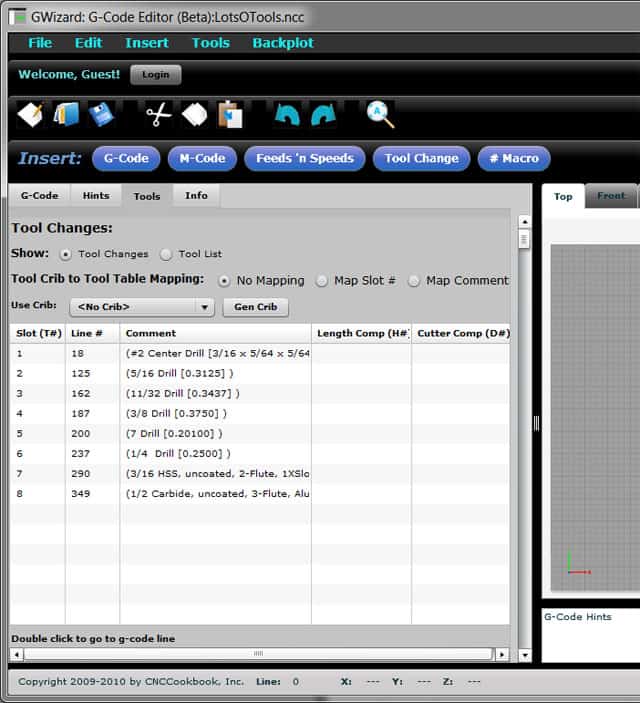
On the lefthand side, where the g-code is, there is a "Tools" tab that brings up the Tools View. The purpose of the Tools View is to tell you which tools are referenced by the g-code program. Here is a typical example:

The Tools View...
There's lots of handy stuff going on here. GWE has gone out and found all the tool changes in the part program and cataloged them here. You can double click on one to go to the tool change. At the top, you can ask to see just a list of tools, one tool per line, so that tools used more than once on the Tool Change list only appear once. That's a good place to start if you don't have a Job Sheet telling you what tools to load. It's also a good place to start if you want to check the accuracy of your Job Sheet.
The Tools View tracks the g-code's notion of a tool, which turns out to be pretty limited. It knows which slot is involved. If you thought to put a comment above the tool change, GWE will capture it to give you a better idea what the tool is. And, it knows which H# is used for the Length Comp and which D# is used for the Cutter Comp. To learn more about tools, we have to go to the Tool Crib, which has a fuller description of tools organized more around the way people like to think of them.
Before we look at the Tool Crib, let's consider how the two tables are connected. We use a process called "mapping" to determine which entry in the Tool Crib corresponds to each entery in the Tools View. Mapping can happen in two ways:
1. You can map by slot. Those are the T#'s, and you can specify that T# "1" in the Tools View represents slot T# "1" in the Tool Crib too.
2. You can map by comment. Suppose you have standardized your comments within your CAM program and the G-Wizard Tool Crib. Then the CAM program will insert the comments into your programs, they'll map properly, and life will be good. This is the recommended approach.
Of course for any mapping you must specify which crib to map to, which is done with the "Use Crib" dropdown menu.
Note the "Gen Crib" button. This button may be used to create a special new Tool Crib with entries that correspond to what's in the Tools View. The Tool View information is incomplete, so GWE has to make some assumptions when it creates the Crib. This option is handy if you want a fresh crib that you plan to assign tools to from other Cribs, sort of the software equivalent of loading your Tool Changer.
Note: Gen Crib is coming soon!
Tool Crib
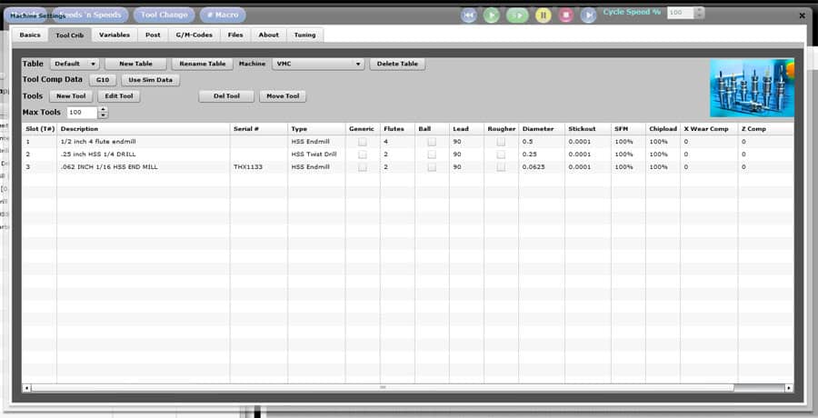
If the Tools View is the g-code program's idea of tools, then the Tool Crib is the machinist's idea of tools. As you can imagine, that's a much richer and more detailed version that applies to more than just one single program. The Tool Crib is one of the tabs on the Setup tool, accessed via the Setup button on the far right of the toolbar:

The Tool Crib...
GWE allows you to create as many Cribs, or "Tables" as you like, using the functions along the top row. I'm going to revisit all the Tool Crib functionality here, because the same app is used by G-Wizard Calculator and its already documented there. Let's just focus on what's important for CNC work and Tool Data Management. In this case, there are a couple of buttons and some fields to focus on. First the fields:
- Slot is the T# for a crib entry. It controls the order the tools are listed in by default. It can be used for mapping Tools View lines to particular Crib tools.
- The Description can also be used for mapping via comments. In this case, the first Tool Crib Description that matches a Tools View Comment in slot order is the winner. If you plan to map via comments, you should avoid the confusion and make all the comments and descriptions uniquely identify one and only one tool. This brings us to Serial #.
- A Serial # is a good way to uniquely identify a tool. If you copy the serial number into the comment and description, it works even better. There are various ways to tag or mark your tools with their serial number.
- X Wear Comp is for Tool Diameter Wear Compensation.
- Z Comp is for Tool Length Compensation.
In addition to these fields, there are two buttons:
- G10 causes GWE to create a g-code program that captures the X and / or the Z comp values for a crib. This is how you export the information in a format that your controller can import easily. The g-code program is filled with G10 operations that load the information into your controller.
- Use Sim Data is how you can import a G10 program's offset information into the Tool Crib. Such a program would have been exported via a Tool Presetter, for example. To import offset information, simply load the G10 program into GWE and it will automatically run and load its information into the # variables of the simulator. What the "Use Sim Data" button does is pull the information out of the # variables and place it into the Tool Crib entries based on which slot numbers the crib has. That means you'll have to make sure there is a slot number for every tool accessed by the G10 program!
This talk of # variables brings us to the "Tool Comp" macro variables.
Tool Comp Macro Variables
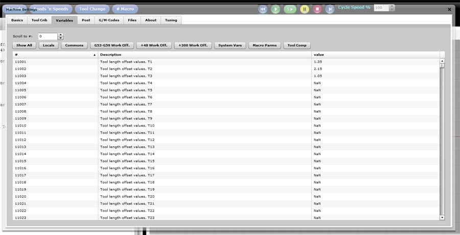
As I mentioned above, when you run a G10 program full of tool offsets, they get loaded into the GWE g-code simulators # variables. These are easily accessible for viewing or editing in the Macro Variable Viewer, which may be accessed as the "Variables" tab from the Setup button on the far right of the toolbar:

Macro Variable Viewer after pressing "Tool Comp Button"...
After bringing up the Variables tab, just press "Tool Comp" to see the Tool Compensation values. You can edit them by double clicking the value.
How Do I Use GWE for Tool Data Management?
Okay, now you've got the basics. How do you actually use this stuff to do something useful?
Let's consider some scenarios.
Putting Together a Job Sheet from a Part Program
So, the design office sent down a part program, or worse, maybe your boss just handed you one that hasn't been used in 5 years and he wants you to set up and run it. First thing's first-you need to know what tools to put in the changer.
So, you load the part program into GWE and click over to the Tools View. Now you can at least see what the tools accessed by the program are. Now let's get a crib going that matches the program. Either use Gen Crib or pick an existing Crib and do some mapping. You'll have to decide whether to map via slots or descriptions.
Once done, you've got all the information you need to at least fill out the Tools section of your job sheet. The next step is to get some Tool Offset information together, so you can run the program.
Offline Tool Presetting and GWE
If you've got a tool setter on the machine, you may not care about Tool Presetting. You load the changed and have the machine deal with using the Tool Setter to figure out the offsets. There are good reasons to want to use a presetter even if you ahve a tool setter on the machine, but I won't go into them here. For now, let's just assume you want to use a tool presetter so you don't have to laboriously touch off each tool.
Instead, you have measured your tool height offsets in the presetter. A tool presetter can be as simple as a height gage, or as complex as a high end laser and digital vision-based system. Let's take it easy and suppose you have a height gage. You take each toolholder with tool, and use the height gage to measure the tool tip from some fixed gage line, where you have zeroed your height gage. For each tool, key that height gage measurement into the GWE Tool Crib under the Z Comp value. Now so long as that length doesn't change, GWE can serve as the record of the information.
Now, when you're making up the Tool Crib for your particular job, do that by moving tools that have the offset information already recorded from another crib into the crib you're using for your part program. Alternately, just assign the slots on the Tool Crib entries to match the appropriate slots from the Tools View. Punch the G10 button and you get back a g-code program with your presetter offsets. BTW, if you punch G10 while your part program is loaded into GWE, your G10 program will be whatever the name of your part program is with the G10 appended. So if it is "MyPart.ncc", you'll get "MyPart_G10.ncc".
Load and run "MyPart_G10.ncc" on your controller. Your offsets are now set for all tools and you're ready to load and run the part program with the right offsets all tee'd up.
If you've got a decent library of preset tools in holders, and you've standardized that library on your CAM program too, this can all go really fast with very few keystrokes.
What to read next
You're pretty much done reading about what GWE can do, but we do still have a Tips and Techniques page.
Be the first to know about updates at CNC Cookbook
Join our newsletter to get updates on what's next at CNC Cookbook.