Video Overview of Setup
The G-Wizard Editor Setup Tool...
Introduction to Setup
The G-Wizard Editor Setup Tool is accessed from the button on the far right, or from the Tools Setup menu choice. It contains a variety of sub-tools accessed by a tab bar along the top:

The Setup Tool...
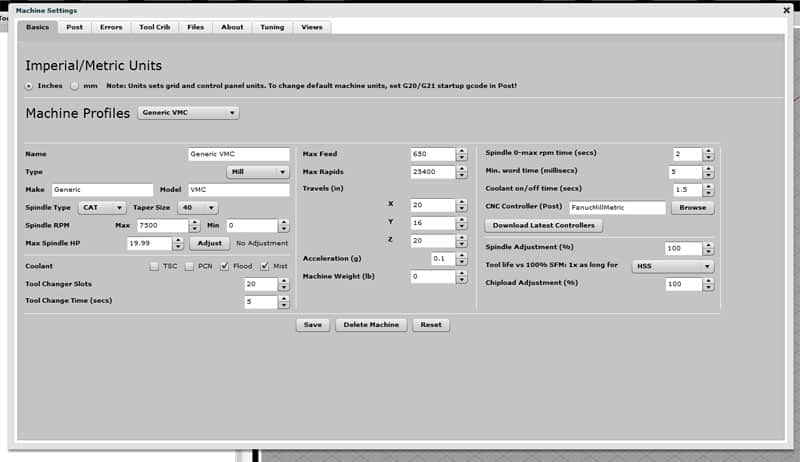
If you do nothing else with the Setup application, be sure to get your Imperial/Metric Units set, a Machine Profile Configured, and download a pre-defined CNC Controller. To access a controller, first click "Download Latest Controllers". This brings all the controller files (they're like Posts on a CAM program) onto your machine. Then you can use the "Browse" button next to the CNC Controller field on the Machine Profile to select one.
The Setup tabs include:
Basics: This is where you decide whether your preferred units are Imperial (inches) or Metric and where you set up Machine Profiles that describe the basic capabilities of your machine tool. The Basics tab is nearly identical to Basics in the G-Wizard Calculator Setup, but the function is slightly different. In particular, you can download a CNC Controller for example. See below for more.
Post: The Post tab is used to tell GWE how the dialect of g-code that your controller understands operates. It covers things like incremental or absolute IJK for arcs. Use the CNC Controller "Browse" button on the Machine Profiles to select a pre-defined controller such as Fanuc or Mach3.
Errors: Let's you turn off selected error messages. Some errors are more along the lines of warnings than actual errors so you may wish to ignore them.
Tool Crib: The Tool Crib lets you define custom tools that are accessible when you go to do tool changes and such. It's also identical to the Tool Crib in the G-Wizard Calculator Setup.
Files: The Files tab tells you where to find the various preferences files and lets you reset them to defaults if needed. It works the same as the Files tab in the G-Wizard Calculator Setup.
About: The About tab tells you a little about GWE, for example which version you're running.
Tuning and Views are aids to GWE's developers. You shouldn't mess with them and they'll go away when the product leaves Beta test.
We'll go into a little more depth on each one that's specific or different in GWE below. For Basics, Tool Crib, and Files, refer to G-Wizard Calculator Setup.
From a g-code perspective, be aware that the default for GWE is Mach3, which is very close to Fanuc in most ways. You will want to go through the various settings and change them to match the way your controller operates.
Basics
The Basics tab is all about setting the units, as well as selecting and defining machine profiles. Let's talk units first. When you change the units, it changes the units for the controls in the editor and it changes the grid but it does not change how the simulator interprets coordinate values in g-code. To change the coordinate value units, use G20 (inches) or G21 (mm). You can either use these in your program, or you can use them in the Setup G-Code under the post tab. So, for example, if your CNC comes up by default expecting mm, put a G21 in your startup g-code.
Always remember, G20 and G21 don't do unit conversion, they merely change how the numbers are interpreted. With G20, X0Y1 refers to X = 0 inches and Y = 1 inch. After a G21, X0Y1 refers to X = 0 mm and Y = 1 mm.
When we say it changes the units for the controls in the editor, that means it changes the units for the XYZ coordinate display down on the status bar, for the Info tab, for the Simulator information that appears below the backplot, and so on.
You can download a pre-defined CNC Controller configuration from CNCCookbook to save the effort of defining all the Post parameters. To access a controller, first click "Download Latest Controllers". This brings all the controller files (they're like Posts on a CAM program) onto your machine. Then you can use the "Browse" button next to the CNC Controller field on the Machine Profile to select one.
GWE will automatically download the latest posts the first time you start up each new release. But, it won't update the post that you are actually using, because that would overwrite any changes you may have made. So, if you want to take advantage of newly downloaded posts, you'll have to Browse and select them manually.
For more on machine profiles, check out the G-Wizard Calculator Setup documentation.
Post
See our Custom Posts page to learn how to customize our existing posts.
Variables
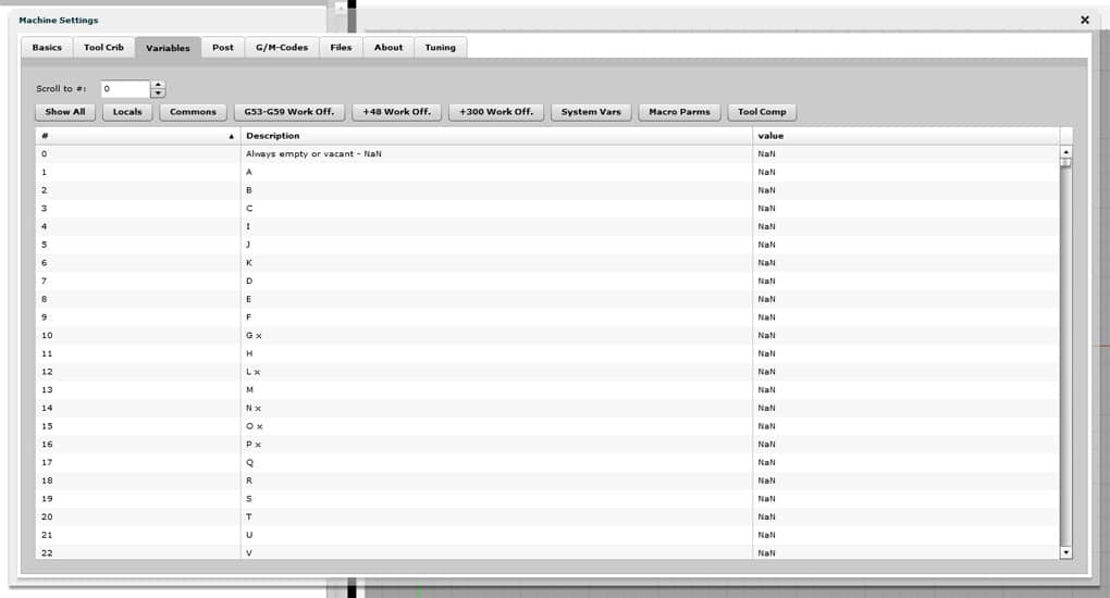
The Variables tab lets you access the internal variables of your simulated CNC machine. These are variables accessible via programs using a "#" and a number and are primarily of interest to programmers writing macros (sometimes called "Parameterized Programming"). But even if you're not writing macros, you may need to access them to set up your work offsets or other offsets so that your g-code program will run properly.
Here is the Variables Tab:

The Variables Tab...
As you can see, the Variables Tab consists of a scrolling list of all the variables together with a set of controls at the top to help you quickly find the variable you're looking for. If you know its number, you can type that into the "Scroll to #" box and get there immediately. If you only know the general category of the variable, you can filter the list using the following buttons:
Locals: These are the so-called Local variables that run from #1 - #33. They're only used within macros to hold intermediate results (hence they are "local" to the macro). When power is turned off, local variables go back to a null value. See your controller manual for more on Local Variables.
Commons: Common variables run from #100 - #199 and #500 - #999. Common variables can be shared among your different macro programs, hence they are "Common. Their status when power is turned of is controlled by the "Volatility" setting under the "Post" tab. See your controller manual for more on Common Variables.
G53-G59 Work Off.: Work offsets are a powerful tool for letting the same program work on multiple parts (as well as many other users). The offsets for G53-G59 are accessible via this button. See your controller manual for more on Work Offsets.
+48 Work Off.: Some controllers add another 48 work offsets beyond G53-G59
+300 Work Off.: And some controllers have still more work offsets, another 300!
System Vars: System variables can be used to read and write a variety of information when programming such as the machine's current position or tool compensation values. See your controller manual for more on System Variables.
Macro Parms: Macro parameters run from #6050 to #6089 and offer a way of passing parameters to your macro programs. See your controller manual for more on writing macro programs.
**Tool Comp:**These variables hold the offset values for Tool Length and Tool Diameter Wear compensation. See the Tool Data Managment page for more details.
Note: At the moment, there's not much you can customize on the Variables Tab.
What to read next
Next stop is the Commands page, where you'll learn what the menu choices do. If you're intent on creating a custom post for your machine, you may also want to check out our Custom Post page.
Be the first to know about updates at CNC Cookbook
Join our newsletter to get updates on what's next at CNC Cookbook.