This page details my efforts to design and build a practical, professional-looking control panel for my CNC lathe conversion. Since I aim to retain manual operations for the lathe, this panel is crucial. After studying numerous CNC panels online, I gained valuable insights and developed plans for my own version.

Sketches
Concept:
The idea is to attach a touchscreen, control panel, and full sized keyboard (in a tray) to a framework made of square tubing. The result should be stable in operation, yet not take up too much space on the bench. It will hopefully also look very professional and nifty. Most of the electronics for the overall lathe will be kept in a NEMA-style electrical box that sits on the floor beneath the lathe.
The panel can sit either to one side of the lathe, or even in front of the area that encloses the motor, making it easy to reach the controls while staying close enough to see what's going on. I like the idea of a sturdy panel better than a pendant. My experiences with radio controlled airplanes tell me that when you have to both exert fine motion and hold the control box it is more difficult.
The MPG and Joystick will hopefully make manual operations easy and natural feeling. A touchscreen eliminates the need for a mouse, and makes it possible to access a bunch of soft configurable controls on the screen if need be. A full-sized keyboard lets me type productively if I need to power some g-code in.
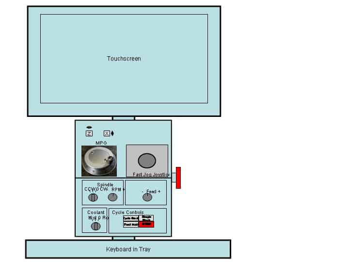
Front View
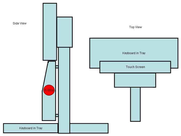
Top and Side Views
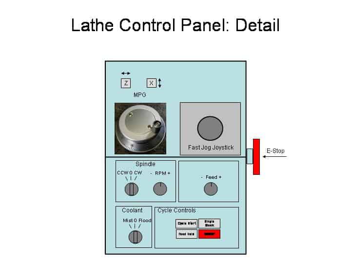
Detailed Functions
Rundown of Detailed Functions (****Left to right, top to bottom):
- Z and X axis selector buttons for the MPG. MPG's are expensive, so I need to buy one and switch it between axes. I'd like to have the active axis light its respective button as well.
- Fast Jog Joystick: This is an arcade-style industrial joystick with 4 microswitches. It'll be connected to fast jog (shift+arrow in Mach) the axes much like the way Centroid controls work. I believe having both fast jog and fine mpg control will promote good manual feel in the machine.
- E-Stop: Fastened to the side where its easy to reach, but not too easy to accidentally reach.
- Spindle: The spindle cluster will allow manual operation of the spindle as well as a spindle speed override pot.
- Feed: A feed speed override pot is provided.
- Coolant: Manual control of coolant is provided.
- Cycle Controls: The cycle controls are used to manage the execution of g-code.
Parts Collected So Far
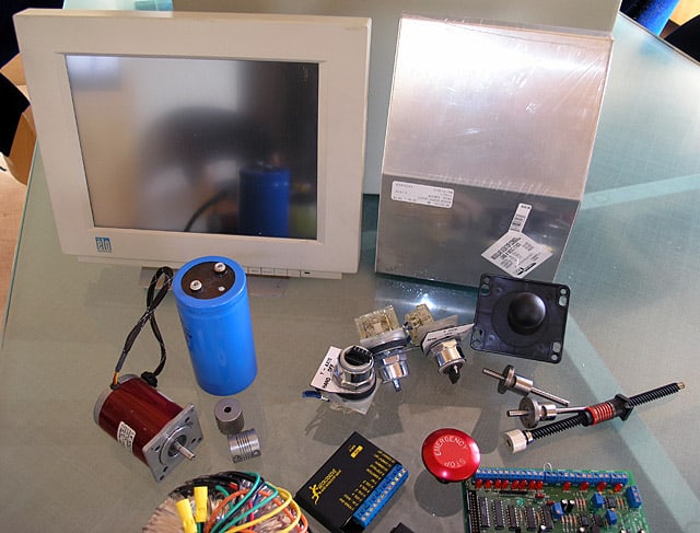
Gathering Up Parts...
Here's where I got the goods:
Slot machine buttons and Joystick: Happ Controls
Micronor Manual Pulse Generator: Rogers Machine
Enclosure: Action Electronics
E-Stop Switch: eBay
Interfacing With Mach 3
Fortunately the Mach 3 software is tailor-made for creating these kinds of control panels and many have come before me. There are a couple of mechanisms by which control is sent from the panel to Mach 3. First is keyboard emulation. One can purchase keyboard emulator cards that convert switch contact closure to a pre-programmed keystroke sequence. One simply connects the device to switches on the panel and then programs the emulator to send along the appropriate key sequences. For something like the fast jog joystick, this is a perfect avenue, and I plan to use this approach for most of my switch contacts in the control panel. The MPG is a little more difficult, but not too bad. I purchased a Combo Breakout Card from Campbell Designs that not only drives the steppers from a parallel port, but also provides the necessary inputs for an MPG. When all is said and done, I think the panel will have a USB or PS/2 keyboard passthrough from the attached keyboard to the emulator card, and then a single keyboard cable back to the PC. In addition, there will be cabling for the MPG, and for power supply connections. I suppose I could mount a wall wart supply inside the panel, connect the touch panel (USB mouse + video back to PC as well) AC into the panel, and have a single power cord. We'll see as the project progresses how clean the design can be.
Building the Control Panel
Initially, I'm just going to paint the panel and support frame PC beige to match the NEMA box and touchpanel, and then use stick on clear labels. Longer term I want to explore creating an engraved panel once I get my mill converted to CNC.
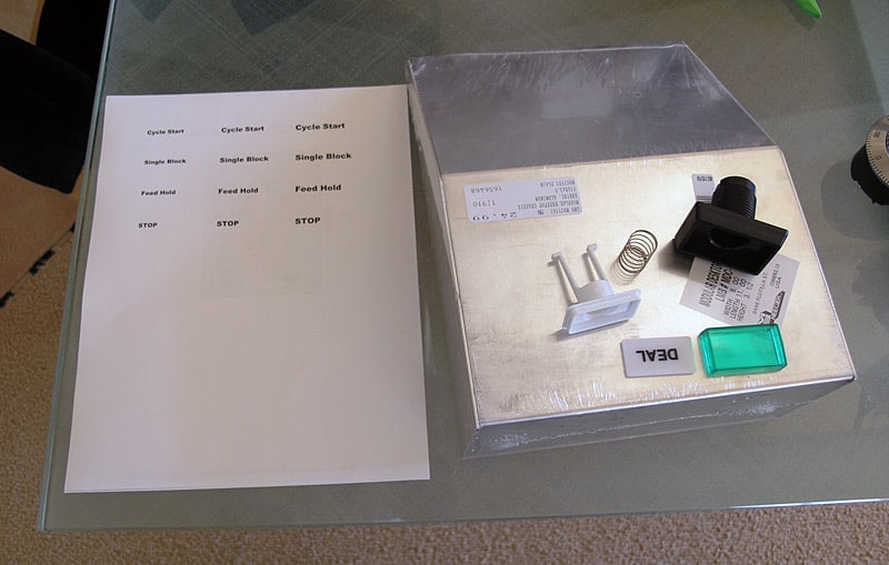
We can use slot machine buttons...
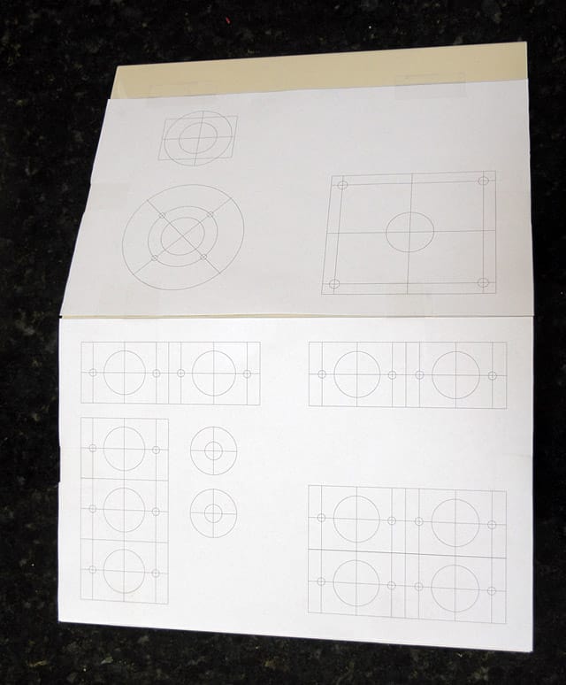
Rhino 3D actual size CAD drawing to layout the holes...
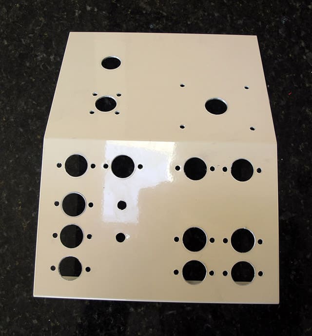
A few chips later, and fresh of the drill press we're ready to mount the controls...
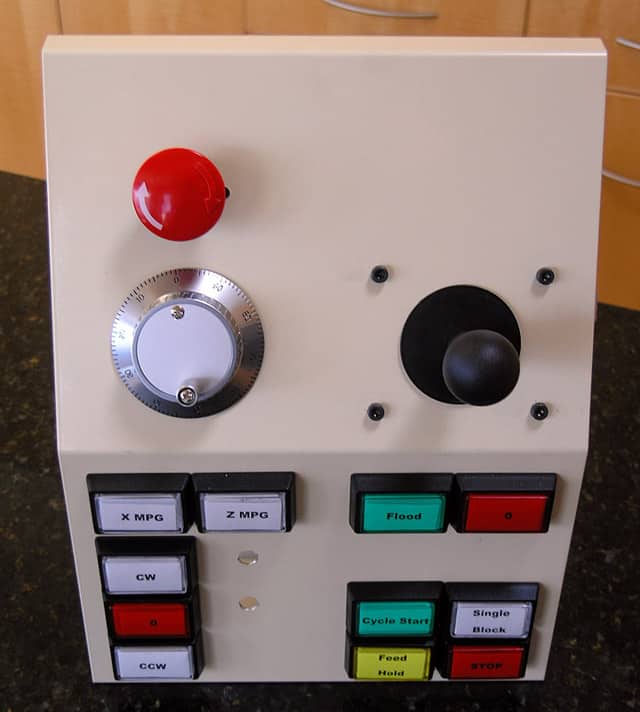
Voila! Still need to purchase 2 pots for spindle and feed overrides. Not too shabby, eh?
Control Panel and Cabling
I plan to use a PC parallel cable and connectors to connect the control panel to the drive electronics enclosure where the GRex resides. Here is my first attempt at mapping the various control panel connections to parallel port pins and thence to GRex:
Grex Lathe Connections
Function
Grex
Parallel Pin to Control Panel
MPG X Selected
Output 6
1
MPG Z Selected
Output 7
2
Spindle Tach Pulse
Input 1
3
E-Stop
Input 2
4
Joystick X-
Input 3
5
Joystick X+
Input 4
6
MPG Step
Input 5
7
MPG Dir
Input 6
8
Joystick Z-
Input 7
9
Joystick Z+
Input 8
10
MPG X Select
Input 9
11
MPG Z Select
Input 10
12
Spindle Off
Input 11
13
Spindle CW
Input 12
14
Spindle CCW
Input 13
15
Coolant On
Input 14
16
Coolant Off
Input 15
17
Cycle Start
Input 16
18
Single Block
Input 17
19
Feed Hold
Input 18
20
Cycle Stop
Input 19
21
Spindle Override
Analog In 1
22
Feed Override
Analog In 2
23
+5VDC
24
GND
25
To facilitate the point-to-point wiring from the parallel connectors, I plan to use a simple screw terminal breakout board:
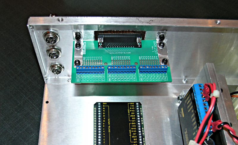
These boards are pretty cheap at $20 a pop and will make my life easier and the installation neater. Wiring the panel just consists of running the point to point connection from each control back to the parallel breakout board. In the driver enclosure, the process continues, with a point to point connection running from breakout board to each appropriate GRex input.
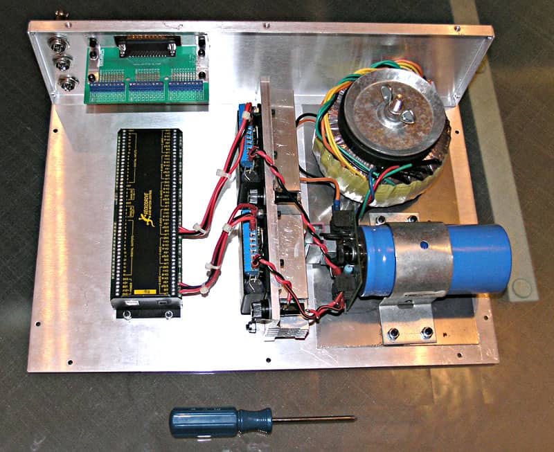
Parallel card for panel and microphone connectors for 2 step motors and limit switches...
Be the first to know about updates at CNC Cookbook
Join our newsletter to get updates on what's next at CNC Cookbook.