The stepper driver electronics consist of a DC stepper power supply, the breakout board or controller, Gecko Drives, and some miscellaneous relays needed to control things like spindle and coolant. I want want to put all of this in one standard rack mount enclosure and use another identical enclosure to hold the PC. Hopefully this keeps the two sets of electronics out of each other's hair from a noise and heat standpoint.
Before beginning my own efforts at this, I spent considerable time scouring the Internet to see how others had approached the problem, and constructed a photo scrapbook of what I thought were good enclosure designs.

DC Stepper Power Supply
Finished DC Supply
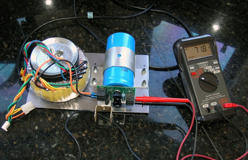
Here is my finished supply putting out 71.8V: perfect!
Transformer: Toroid from Parts Express with a 56V secondary (among several others). $29.95
Ajax CNC Rectifier Board: $29, has inrush protection.
Electrolytic Capacitor: eBay, about $3.
Specs: about 72V DC @ 5A out.
This about twice the amperage needed for my 2 little steppers based on the design work below, which suits me fine. The chassis and mountings consist of a piece of 18 gauge steel, a pipe clamp, and an expander rubber pipe plug from the hardware store. Miscellaneous parts and hardware probably cost me in the neighborhood of $15, so the total power supply cost came in at about $80.
Designwork
I'll be constructing a classic unregulated DC power supply along the lines suggested on the Yahoo Group for Gecko Drives. There is a white paper in their files section that gives a detailed description for how to design one of these simple power supplies to fit your particular step motors. In my case, the design exercise was done in an Excel spreadsheet that looked something like this:
Input Parameters
Stepper Rated Voltage 24 volts
Stepper Rated Amperage 3.4 amps
# of Steppers 2
Driver Max Voltage 80 Gecko's max rated voltage
Max. Stepper Over-Voltage 25 x rated
Desired Min Over-Voltage 3
Zener Requirement Range 15% Use clamping diode if voltage is within this percent of drives max!
Idealized Outputs Power Supply Rating 2.27 amps
Target Voltage 80 volts
Undershoot no If "yes" the steppers requires too much voltage for the driver
Ideal Transformer Secondary 57.14 volts
Transformer Rating 181.33 voltamps
Min. Rectifier Ratings
Voltage 57.14 volts
Current 2.27 amps
Filter Capacitor
capacitance 2,266.67 microfarads
voltage rating 100 volts
All these values were derived by formulas on the Gecko site. Essentially, you want a voltage that is about 20x what your motors are rated for (the Gecko site explains why, don't worry, the Geckos won't burn out your motor if you follow their directions). So, you work backwards to the transformer. Rectifying (converting AC to DC) will multiply the voltage by 1.414. So you need a transformer that is 20x/1.414 volts, where x is the motor voltage. Gecko also recommend not feeding their drives more than 70v, so keep that in mind too.
The toroidal transformer I found came from Parts Express, and as you can see, it worked out almost perfectly for this application and was cheap as well: $29.95. While I was on the site I also purchased a bridge rectifier that was way overrated for this application, but that was also cheap at only $2.50. So far this CNC stuff is not too bad!
I purchased some 3500 mF electrolytic capacitors on eBay. They're a bit larger than what the design calculations require, but there is no harm in that. The extra capacity will just smooth out the current supplied a little better. The required circuit is quite simple:
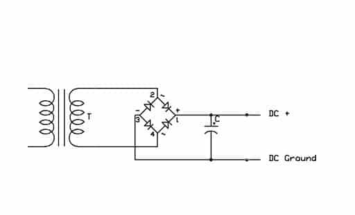
Note that some folks will tell you to put a zener diode across the DC outputs to deal with back EMF. This is a very controversial subject, and one Mariss F. himself ultimately weighed against over on the Gecko board. The diagram above used to have one, but I got tired of the controversy and took it out. Another one that comes up a lot is a suggestion to put a resistor to discharge the capacitor. I've seen a number of posts that indicate the Geckos will discharge the cap reasonably quickly however, so I didn't worry about that.
Rectifier Board and Capacitor
In fact, I found a short cut so I didn't have to worry about anything but the transformer and cap. You can do a really slick thing and purchase a card from Ajax CNC for $29 that gathers all of those electronics on a small board that mounts atop the capacitor:
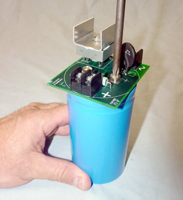
Ajax has all kinds of useful CNC components, including transformers, capacitors, control panels, MPG's, and most of whatever else you might need. Be sure to check them versus other suppliers you may consider. Tormach sells a similar board, but it was quite a bit more money last I checked. PMDX also make a nifty power supply circuit board.
I bought the capacitor on eBay, a box of 9 was $27. Cheap!
Transformer & Phasing
With the Ajax board and capacitors, you just need a transformer to finish the supply. I got mine from Parts Express for $29.95, and it's a toroidal. It had a sticker on it telling which wire was which. If you don't have a proper description of the wiring for your transformer, you'll need to check the phasing yourself. Transformers often have multiple sets of windings, for example so the same transformer will work with 110V or 220V. For example, if there are 2 110V primaries, you connect them in parallel for 110V and series for 220V operation. It is even more coming to find this flexibility in the wiring of the secondaries. If you connect the wire wrong, you get a short circuit, so you have to phase them. Phasing is the process of figuring out which wires coming out of the transformer you want to use in what way for your application.
This is not hard to do, but you want to do it carefully. First, the voltages involved are dangerous-BE CAREFUL WHAT YOU TOUCH AND WHAT TOUCHES THE TRANSFORMER AND OTHER WIRING! Beware of both shock and fire hazard.
_https://www.du.edu/~jcalvert/tech/transfor.htm_
For example just connect one primary by disconnecting ONE of the red wires, leave the 2 blacks & one red connected and power up and test the voltage between the two reds, you should get near zero volts, if so connect the reds up again, if the breaker trips with this test then the secondaries are phased wrong.
As far as the primary is concerned if it is a centre tapped winding at 115v then it would not matter if you went from blk to red or red to yellow for the 115v input. In any case hook up the primary first and check the secondary ac voltage on blu to blu and grn to grn if they are the same voltage on each they can be paralled up for double current rating, the only thing is they have to be phased right, they may have a marking on one blu and one of the grn wires. The AC voltage you are getting on the secondary will be mulitplied by 1.414. -1.2v for a DC bridge rectifier supply with capacitance smoothing. If you need help phasing the secondaries more help can be given, if the secondaries are different voltages then you cannot parallel them.
To phase the secondaries, take ONE wire from each sec. and wire together, then measure the ac voltage on the two open ends, there should be close to zero voltage, if you get double the voltage of one sec. then swop one of the connected wires for the other of the same secondary. When you have zero of the two open ends then they can be paralleld.
I think you have it, once you get 0v across the two open ends, then these two open ends can be connected together , what you are doing is connecting both secondaries in parallel, one across the other so you end up with two connections with a blu and grn connected at each end. When you tried before, you probabally had them connected this way but they were not phased properly. BTW did you get this from the guy who sells them on ebay, as usually he marks the start winding of each secondary by a piece of black heat shrink.
Gecko Drivers
I'll be using the Gecko 202 step motor drivers. The 201's are cheaper, but the 202's are a little more rugged and "beginner-proof". The extra cost is worth it to me. I used a piece of extruded aluminum heatsink material from eBay to create a tray for the Geckos and their fuses:
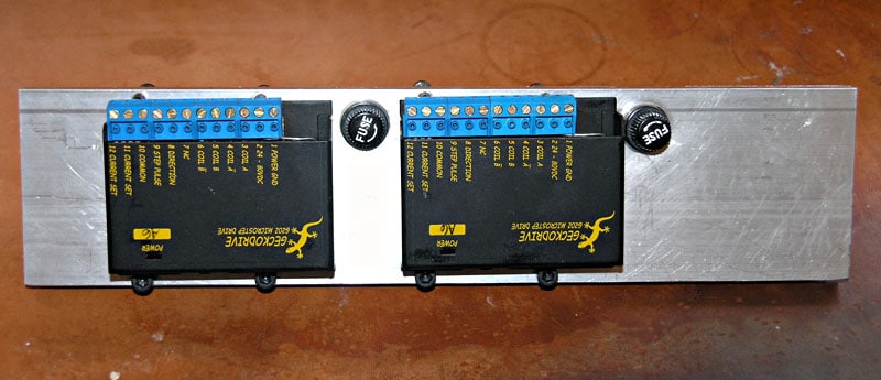
Gecko Drives for X and Z Axes with Fuses Mounted on Heat Sink...
Be sure to put the fuses in the circuit between the DC power supply and the Gecko drive rather than between the Gecko drive and the motors. The latter will encourage the Gecko to self-destruct if the fuse blows.
PC Interface / Breakout Board: GRex
My choice of a breakout board to connect the PC to the Gecko's is a bit avant garde, at least in May of 2006 when I made the decision. Because my control panel has so many controls, I would have to use several conventional boards to connect everything-either 2 parallel breakout boards or one parallel and a ModIO board. In addition to the breakout boards, I would need a keyboard emulator. While the boards from Campbell Design and Rogers Machine are tried and true, I have decided on a newer solution. The GRex, or G100, is a product made by Geckodrive that is chock full of I/O ports and is capable of handling a whole slew of I/O connections. One is on order.
The GRex has the potential for much higher performance than the parallel boards because it allows Mach to offload a fair amount of its tight timing loop operations onto an onboard CPU. I don't really need that extra performance for this lathe, but it's nice to know it's there. My biggest challenge at this point is that Mach IV and GRex are still pretty experimental as I'm writing this, so I'm definitely out on the "bleeding edge".
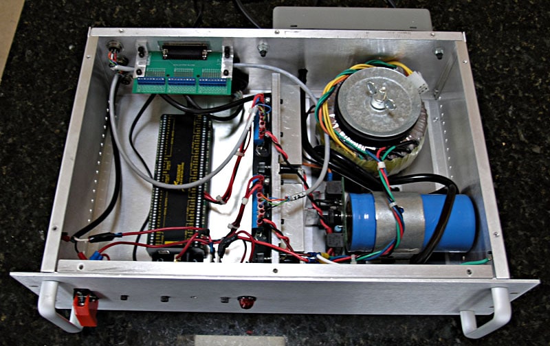
GRex, Gecko Drives, and DC Stepper Power Supply Mounted in Enclosure...
Spindle and Coolant Control
Coolant Control
This one is easy. I just need to control a relay from the GRex. The relay will control AC power to a receptacle mounted on the back of the enclosure. This way, I can use any AC pump I find for the coolant and the pump will be turned on and off by the relay as needed. I'll use a mechanical relay so that if I needed to switch to a DC connection that would work too. I have some thought I might choose to control air rather than flood coolant because its less messy and I wouldn't have to build an enclosure for the lathe. Also, I have a nifty little vortex tube cooler that would be just the ticket for my lathe. We will see.
It's been noted that a suppressor diode across the coil helps reduce noise, so I need to look into that as well.
Spindle Control
The spindle control is a little bit more complex because there are three functions: on/off, direction, and speed. I am planning to mount the circuitry for spindle control in a separate chassis connected back to the GRex using microphone connectors and 6-conductor shielded cable. I am hoping this will help keep the noise from the speed control away from the rest of the system. This remote chassis will be mounted back-to-back with the speed controller on the lathe itself. I intend to install a load meter, which is just an ammeter telling how much current the spindle is drawing, as well as a tachometer. All AC to this remote chassis will be via the switched receptacle strip on the back of the main enclosure. That strip is switched by the E-stop circuitry, so we'll be sure the spindle gets shut down as well as the coolant in the event of an emergency stop.
Here is my current schematic for how this remote spindle and coolant control chassis will be wired:
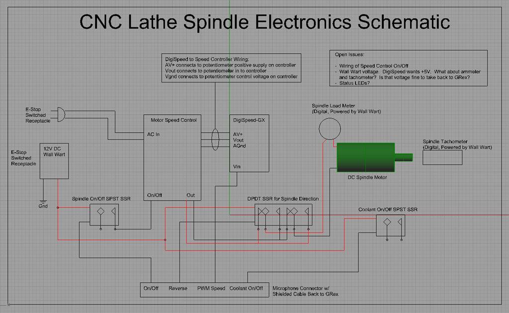
Let's walk through its operation.
First, the on/off circuit. I've shown it as an SPST. I need to go back and look at my controller and see exactly what it wants to turn the spindle on and off. The GRex digital outputs basically take the voltage down to 0V when they are "On", so I think of them as grounding the connection. That's why the On/Off relay takes positive from the wall wart and hooks the other "coil" terminal to the GRex line.
Next, we have the reversing circuit. This is a common DPDT set up to reverse direction. I will again use a solid state relay (SSR) for this purpose. All it does is switch the polarity of the 2 output lines from the speed controller.
Speed control is via the excellent Homann Designs DigiSpeed-GX, which is especially designed for applications like the GRex. The GRex puts out a variable analog voltage (0 to +5VDC) on one of its output lines. Mach 3 is set up to work this way with a GRex or breakout. The DigitSpeed board will convert that variable analog to an analog voltage suitable for driving a speed controller, replacing the potentiometer normally installed there. The important function it provides is isolating your GRex or other breakout board from the motor controller. Failure to do so can quickly "fry" your GRex or breakout board!
Coolant is a simple relay that will pass through AC to a receptacle, said AC coming from the E-stop switched receptacle. This way I can just plug a coolant pump or whatever into the outlet. I may not do the coolant right away, as there is some question in my mind whether I'll ever run flood coolant on this lathe. It might make more sense to stick to air or a mist system.
There are a few open issues noted on the drawing, but I'll tackle those when I'm closer to building this little enclosure.
Wiring, Connectors, and Noise, Oh My!
I bought a 500′ spool of 6 conductor shield 22 AWG cable from Action Electronics. For connectors, I'm using some microphone connectors, also from Action.
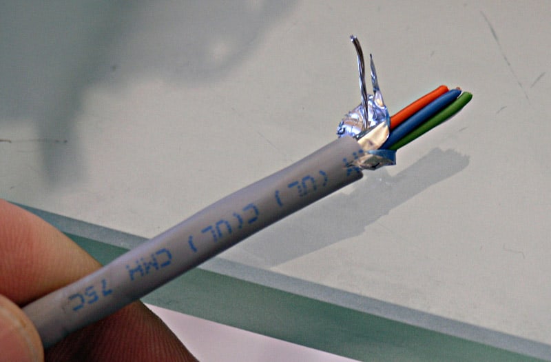
6 conductors and a foil shield: this is the right cable for my step motors!
For others who may read this, you want to use shielded cables or noise will make your system unreliable. Other thoughts:
- You can use CAT-5 cable for encoders or limit switches, just be sure you use the twisted pair feature and pair each signal with it's ground to provide noise immunity. Apparently this idea has been blessed by none other than Mariss F., Mr Gecko, himself.
- DIN cables such as are used as MIDI patch cables in the music business and older keyboard cables (before the PS/2 and USB styles) in the PC business are another possibility. Even Radio Shack carries some DIN cable componentry. DIN for MIDI applications have 5 conductors plus a ground/shield and are supposed to be rated to 2 amps @ 100V. What's nice is you can get premade DIN cables in a variety of colors and lengths. If they'll serve the power needs of your system, they could be quite convenient. Mini-DIN is the PS/2 keyboard connector, and is also shielded. It might be useful for limits and encoders. Cables are available already made up. Note that Homann sells a mini-DIN breakout board that would make it easy to connect to your mini-DIN cables with point to point wiring.
MIDI DIN patch cable...
- Cinch connectors are another common type of connector used for motors. They will carry a bit more current than DINs or microphone connectors.
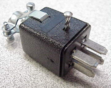
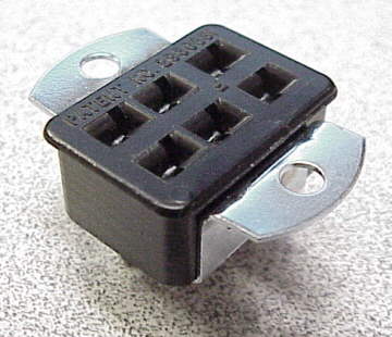
Cinch connectors...
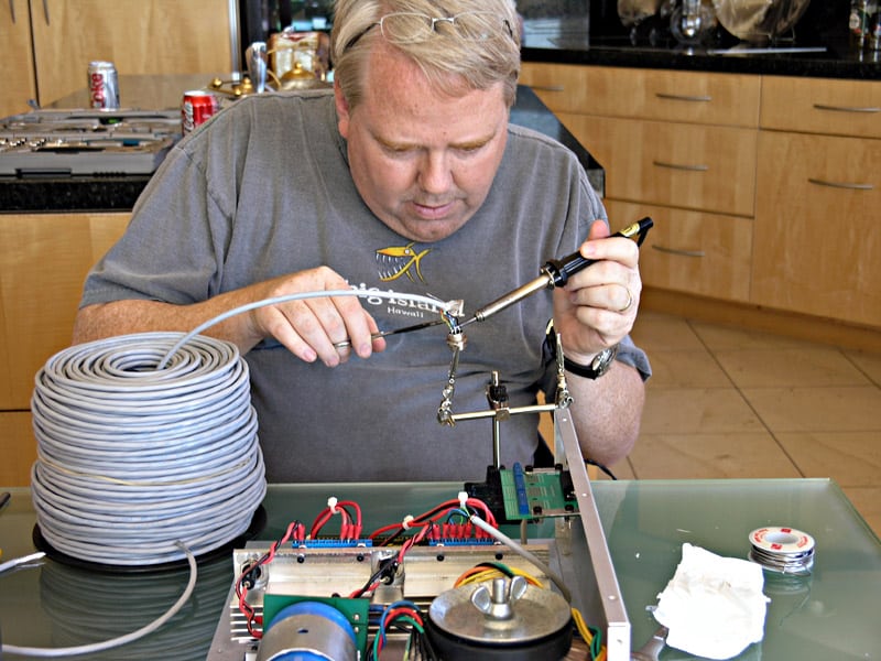
I quickly remembered how much I hate soldering connectors...
When I started soldering my connectors, I quickly remembered how much I hated this task. I used to regularly have to make up serial and parallel cables for a part time job I have in college at a computer store as a technician. The technique I was trained on what to fill each pin with solder first, "tin" the wires, and then heat each pin and plunged the tinned wire into the pin's molten pool of solder. It actually works pretty well and it won't take long to finish the connector. You'll go crazy if you don't have some way of holding it while you do the soldering-I have a cheap alligator-clip based solution I got from Radio Schlock. The other thing I discovered is that it is much easier to hold and manuever the wire with hemostat clipped shut over it than with a needle nosed pliers.
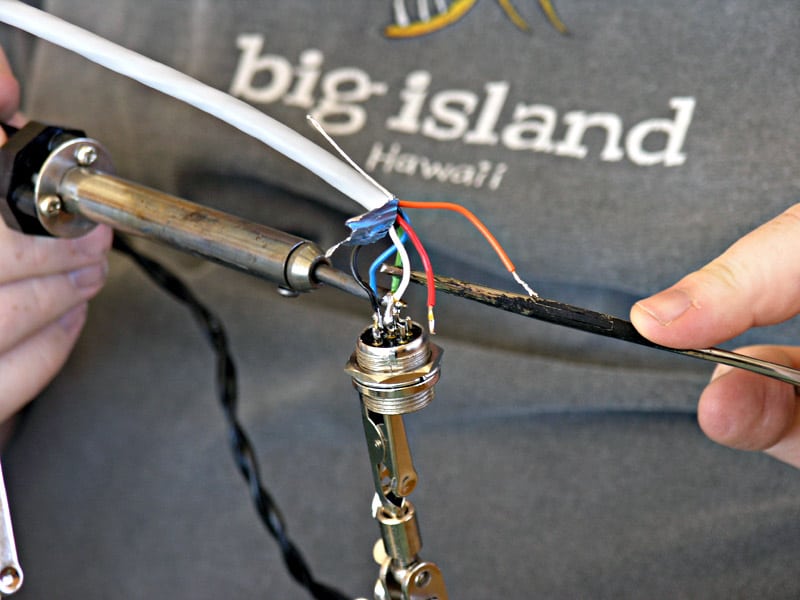
Plunge the wire into the pool of molten solder in each pin!
E-Stop and Time Delay Power On Circuits
Emergency Stop and time delay power on are important safety features to provide for the driver electronics. Time delay power on ensures there is adequate time for the GRex to boot up before any power is available to the Gecko Drives. This is to make sure no inadvertant glitches can send a motor signal before the GRex is awake and fully ready to assume control.
The Emergency Stop is a fail safe means of cutting power to the spindle and axis motors by hitting one switch.
How did I implement these functions?
I've used a switch with safety cover to turn on the system. You will have to lift the cover and flip the toggle up. Pressing the red safety cover once the system is on will open the circuit and cut power.
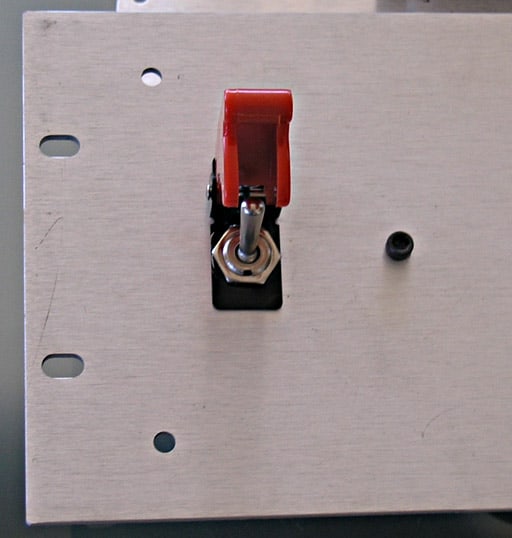
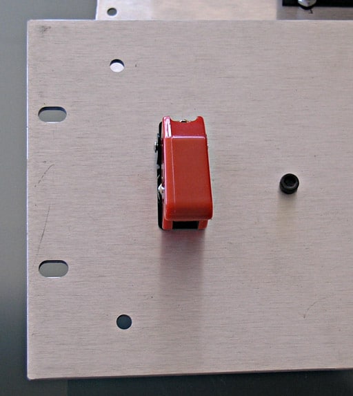
Flip up to supply power, press down on safety cover and power is cut...
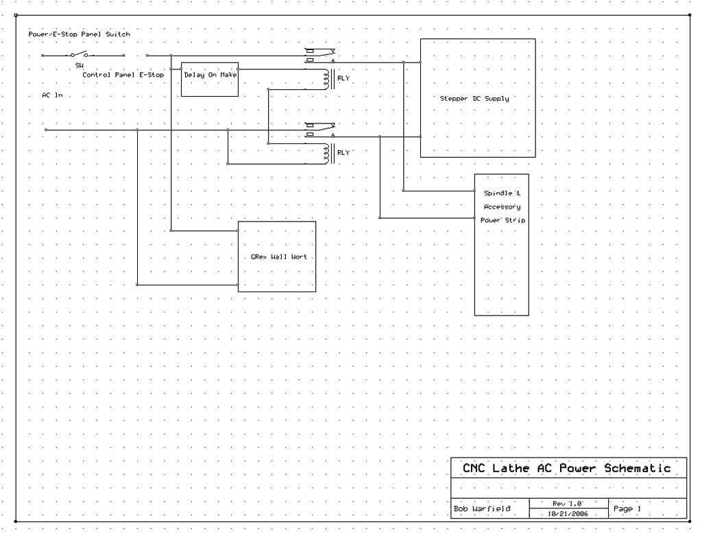
This master on switch can therefore serve as the E-Stop switch. Slap it down and power is cut. Power from this switch goes to two places. First, it goes to the GRex wall wort as we want it to power up first. Second, it goes to a Delay On Make timer relay. This device waits an adjustable interval before letting power go on through. That interval gives the GRex time to boot up. The output of the timer relay will be a much larger (10-20 amp) solid state relay that supplies power to the DC power supply for the step motors, as well as to a power strip, where I can plug in the spindle VFD and any other accessories that want delayed power up. I got my Delay On Make timer relay from McMaster Carr for about $20.
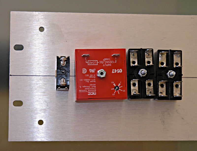
Back of Front Panel, Left to Right: E-Stop Power Switch, Delay On Make Relay, SPST Relay, and SPST Relay...
In addition to the safety covered master on-off on the driver electronics enclosure, there is an additional plunger-style E-Stop on the lathe control panel. I'll wire this up in series between the Delay On Make Timer Relay and the heavy duty contactor. Hitting that E-Stop plunger will therefore cut power to spindle and stepper motors. I'll also drive any accessories such as coolant pumps of this circuit as well.
Here is a schematic of the overall E-Stop and Delayed Power Up circuitry:
Home/Limit Switches
I am using two switches on each axis as combination home/limit switches. The X-axis (long axis on the lathe) is constructed using simple clamp-on brackets to hold roller microswitches:
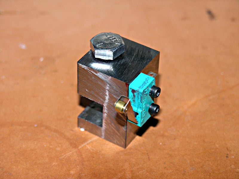
X-Axis Home/Limit Switch
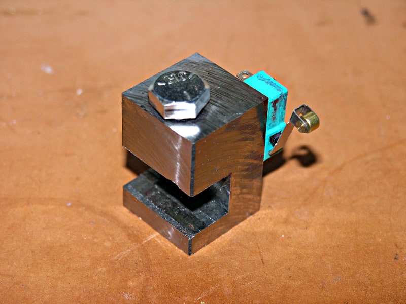
X-Axis Home/Limit Switch
The plan is to wire these switches in series in a normally closed configuration. If the limit is hit on any axis, the switch will open the series circuit. Likewise, if there is a connection problem, the system will fail open and the limit will be tripped.
These switches will be connected using the same shielded cable and mic connectors I am using for the step motors. The GRex uses 12V for power, and I am hopeful this level of voltage together with the shielded cable will be sufficient to avoid any noise on these lines. In addition, the normally closed mode of operation should also make for better noise immunity I would think, as a noise spike would seem to lead to falsely tripping the switch only in a normally open configuration. In practice, we will have to see.
Blinkin' Lights
I like the idea of front panel lights that flash when there is activity on an axis. Could be a useful troubleshooting adjunct, or just a nifty bit of eye candy to make things look more "professional." I've done a small amount of research so far on how to make this work out. Firstly, a company called CAndCNC has a little card to do this that works with their breakout boards. It's called the SDM-100, or in some places referred to as the S&D-03. I sent them a note to see if pinout is available because it is set up to work with a dedicated feature connector on their breakout boards, which of course I am not using.
There was a brief exchange on CNCZone with some clues as to how to do this more directly. The suggestion was thus:
+5 thru current limit resistor thru led (--l>--) to ground. Don't worry, if you botch the polarity on the led, it simply won't light - haven't fried one yet by reversing it. When the +5 line goes HI, the led will glow. Calcing the resistor value is the only "hard part". I use this formula: (source voltage -1.5)/.010 = resistor value in ohms rounded up to nearest standard value. This puts about 10 milliamps into the led. For 5 ma, change the 0.010 to 0.005. The led should light either way. 1/4 watt resistors should be fine.
This was later amended by Mariss by the following:
The G100 general purpose outputs are common collector. Reverse the LEDs and take the anodes to the G100 +24VDC terminal. Same for your SSR1.
Which seemed simple enough to me and worth a try. I may have to think about putting LEDs on all of the interesting outputs for the G100.
Be the first to know about updates at CNC Cookbook
Join our newsletter to get updates on what's next at CNC Cookbook.