I picked up 5 210 oz in Pacific Scientific step motors from eBay (I love eBay!) for $34. These should be perfect for driving the leadscrew and cross slide:
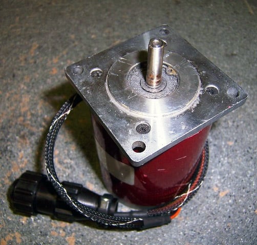
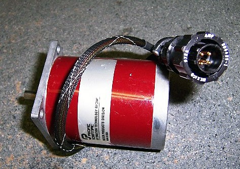
Pacific Scientific 210 oz in NEMA 23 Stepper Motors...
The motors have 1/4" shafts with a flat for setscrews, and no encoders.
Mounting the Steppers to the Shafts
Given the size of my lathe and the 210 oz in rating of these motors, my intent is to direct drive. I don't need the torque multiplication of gears or timing belts, and the simplicity of direct drive appeals to me. Here are the shaft dimensions:

Lathemaster 9×30 Shaft Dimensions...
Since I am direct driving, a simple Helical Beam Coupler will suffice to connect the motor to the shaft:

Helical Beam Coupler...
These little guys take care of slight inaccuracies between the two shafts without introducing any backlash. In exchange you must give McMaster Carr or some similar organization almost $30 apiece. They can be had with different bore sizes on each end, which is perfect since the steppers are 1/4" shafts, the cross slide is 15/32" (!!! or maybe 12mm, hard to say), and the leadscrew is 5/8". So, we need the following:
Leadscrew: McMaster Carr 6208K14, $27.58. 1 1/2" OD, 2 3/8" OL, 1/4" to 5/8"
Cross Slide: McMaster Carr 6208K8, $24.96. 1 1/4" OD, 1 1/4" OL, 1/4" to 7/16"
Since the cross slide is such an oddball size, I will have to bore the coupler slightly as the off-the-shelf part is slightly undersized. Given these couplers, I will then fabricate the normal mounting plate with spacers arrangement. The NEMA 23 square plates on the motors will be bolted to spacers, which will in turn be bolted to a plate that is bolted to the lathe:

Generalized Direct Drive Step Motor Mounting Arrangement...
Once all is running well, I will want to fabricate some sheet metal covers to protect the couplers from flying chips, keep fingers out, and generally make the installation a little neater.
Hold the Presses: CNC Machined NEMA 23 Mounts
I found these NEMA 23 motor mounts on eBay for $25 and couldn't resist. They are so much nicer than using two plates with spacers. By positioning the hole on the bottom, the helical beam coupler and shafts are protected from flying chips or coolant.

X-Axis (Leadscrew)
I'm thinking of using the existing banjo mounting shaft that the change gears use. The change gears just use a pinch collar arrangement around this shaft:

Banjo Pinch Collar...

Mounting Plate Will Attach to Banjo Mounting Shaft...
In the photo above I call out two potential holes that would tie the plate to the lathe bed (circles with "?" in them). I decided not to use those holes in favor of the method shown in this drawing below:

Attachment to Banjo Shaft...
I did not thread into the banjo mounting shaft. Instead, I just used 2 set screws at 90 degrees. It was an easy couple of hours to fabricate the Z-axis mount:
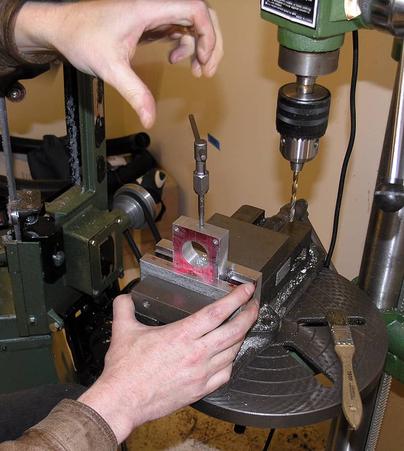
You can see the mounting plate here. My brother is threading for one of 2 set screws...

Here's what it looks like on the lathe. Very sanitary, no? It's on there to stay as well!
Z-Axis (Cross Slide)
There are a lot fewer options for the cross slide unless I want to do some major fabrication (no thank you!). I'm looking at using the existing bolts that hold the piece with the handwheel dial pointer engraving:

Likely X-Axis Mounting Holes...
So, I will build a square plate with holes for the shaft, 3 mounting bolts to the lathe, plus the 4 NEMA-spec mounts for the motor spacers. BTW, they're hard to see in the picture, but there's a nice little thrust bearing on the shaft underneath the round piece as well as the one that's visible on the shaft. Together, I'm sure they contribute to the nice handwheel feel on these Lathemasters compared to cheaper Asian lathes as well as getting rid of backlash due to axial movement of the leadscrew. Here is a cutaway view of how it will all work:
 .
.
The mounting plate captivates the first thrust bearing as well as providing the attachment to the cross slide base via the 3 allen head bolts. The leadscrew shaft protrudes through this plate, and there is a shaft adapter. Since the leadscrew is bored and tapped, the shaft adapter serves two functions. First, it reduces shaft diameter to better fit our helical beam coupler. Second, the adapter presses against the thrust bearing so that by tightening the axial allen head threaded into the leadscrew against the adapter we take up any axial play in the leadscrew. You can see the shaft adapter a little more clearly if we take away the CNC Bracket/Motor Mount:
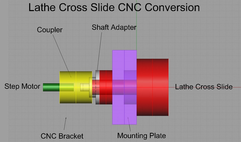
That red disk between the shaft adapter and the mounting plate is one of the thrust bearings.
Be the first to know about updates at CNC Cookbook
Join our newsletter to get updates on what's next at CNC Cookbook.