Delta 3D Printers
You're probably wondering, "Why a Delta 3D Printer?," or perhaps even "What is a Delta 3D Printer?"
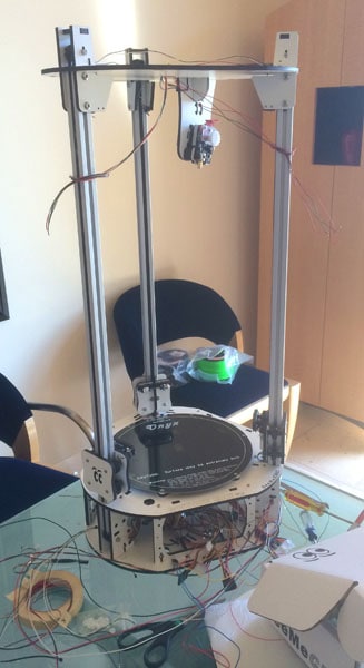
Delta 3D Printers use a somewhat different geometry than most CNC machines people are used to. Instead of the rectangular axes, it is more triangular in function. The legs run up and down 3 vertical tracks. Since each leg can be a different distance on its track above the print surface, the print head can be positioned anywhere within the 3D work envelope. Here's what a typical Delta 3D Printer looks like:
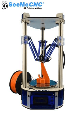
That's an Orion Delta 3D Printer from SeeMeCNC. It's the ready-to-run version of the Rostock CNC Kit we purchased for CNCCookbook's 3D Printing needs.
Deltas are awesome for printing tall skinny objects and make very efficient use of table space. It's also claimed that Delta 3D Printers can print faster than their rectangular (Cartesian) siblings.
I liked the unconventional geometry of the Rostock, the large build volume, and the fact that 3D Hubs was giving it a pretty high review rating at the time. It still gets an 8.6 there, which is not too shabby considering it's been a few years now since I bought mine.
Rostock Max V2 Kit
This article walks through our Rostock Max v2 Delta 3D Printer kit from SeeMeCNC and chronicles what it's like to build one. Here's the contents of the big box delivered to our door:
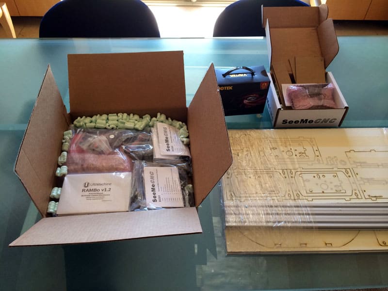
Related parts are individual bagged into parts kits. Printer structure is laser cut melamine...
The parts are neatly divided into individually bagged sets of related components plus the laser cut melamine that makes up the bulk of the printer's structure except for the vertical rails. The manual needs to be downloaded from the site, which is nice, because you can scan through the manual ahead of time to see how hard it looks to build the kit (a finished albeit slightly smaller work volume version is available for a few hundred dollars more).
The first step after unpacking is to get the melamine parts punched out of the big sheets. They're held in place with masking tape and a layer of masking paper that protects the melamine from the fumes and burning debris form the laser cutting process. The whole thing smells pleasantly of burnt wood, kind of like a campfire, while you're peeling off all that tape and getting the parts organized. The laser cutting was done very well. The manual warned that we might have to use an Xacto knife to free some parts, but all of ours popped out very easily. These melamine parts go together with a tab and slot construction. It doesn't take very long to conclude that their second-generation version has probably gone through considerable refinement. The manual has been complete and detailed to this point and everything was very easy to assemble. They estimate 20 hours to build the kit and we took about 3 1/2 hours to get to our first stopping point, which was through page 50 out of 250 pages in the manual. I'd say their estimate is pretty decent and that most people who are at all handy at building things will get it done in a reasonable length of time. We're just at the first stage, so there may be more challenge ahead. If so, we'll report on it.
After getting the laser cut melamine parts ready, our next step was to assemble the lower base:
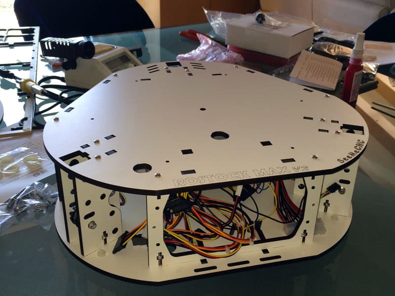
3 1/2 hours later, the base is more or less finished...
Construction is tab and slot with bolts into captive nuts holding everything together. As is typical, things seem flimsy until you get it bolted together and then they're a lot more rigid. Here's what I mean by captive nuts and bolts:
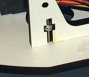
Captive nylock nut and bolt...
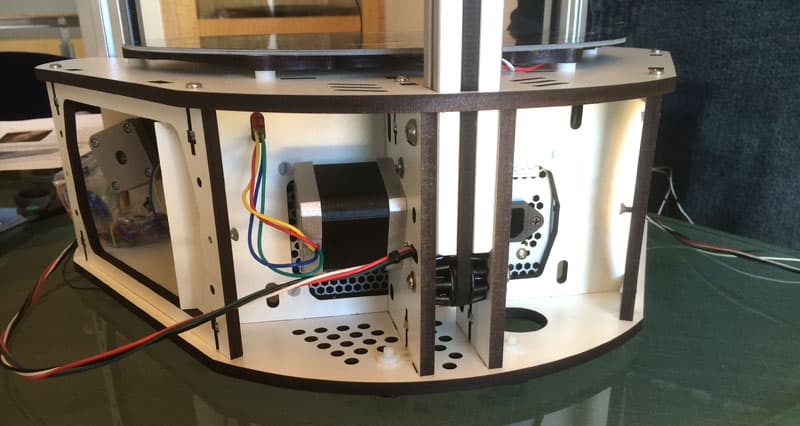
Inside the base is a standard PC power supply and three little stepper motors with cog belt pulleys and belt tensioning ball bearing idlers. This all goes together very easily. The most challenging thing, and its not very challenging if you do much wiring at all, is to remake the wiring harness for the power supply with the appropriate connectors to power the needs of the 3D printer. Basically this means cutting some of the wires lose from standard PC power supply connects and installing some crimp-on spade connections and a screw-terminal connector for the RAMBO controller board used by the Rostock. No biggie.
The kit has been very straightforward so far. We didn't even bother bringing up a bunch of tools from my garage shop. Just a couple of screw drivers, a Leatherman (!), and my wiring toolbox for the wire cutters and crimper were all that we've needed so far. The most time-consuming part of this first phase was peeling off all the masking paper from all those melamine parts. Hopefully the second part will go faster. I recommend getting the whole family involved peeling off that masking paper. It's really no big thing and just takes a little fingernail effort to get it started. A few extra hands will make that work go a lot faster.
Part 2
Part 1 got us to the point where the base was assembled, though there is quite a lot of wiring yet to be done there. For part 2, I worked about 7 hours evenly split across a Saturday and Sunday afternoon. This got me to about page 120 in the manual. The printer is considerably further along and taking shape.
First up for this construction stage was to glue the two resistors that heat the hot end and melt the plastic filament into the hot end assembly:
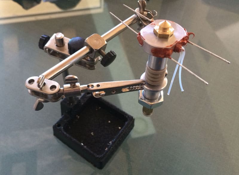
High-Temp RTV secures two resistors and a thermistor in place…
This is no big deal, but it’s worthing doing it early as they suggest so the RTV will have dried completely by the time you start fussing with the hot end. Note the size of the filament nozzle on that hot end–it’s a tiny little hole that’ll be laying down the plastic on your 3D part.
Next up was the Onyx Heated Bed. A number of the components from this complete kit can be purchased for use in other 3D printer projects, and the Onxy is one of them:
This view shows the Onyx Heated Bed on some standoffs as well as a little of the detail around the towers and stepper drive for one of the “axes”…
All was easy with the kit up until came time to feed a bunch of wires up the center hole in the extrusions for the axis rails:
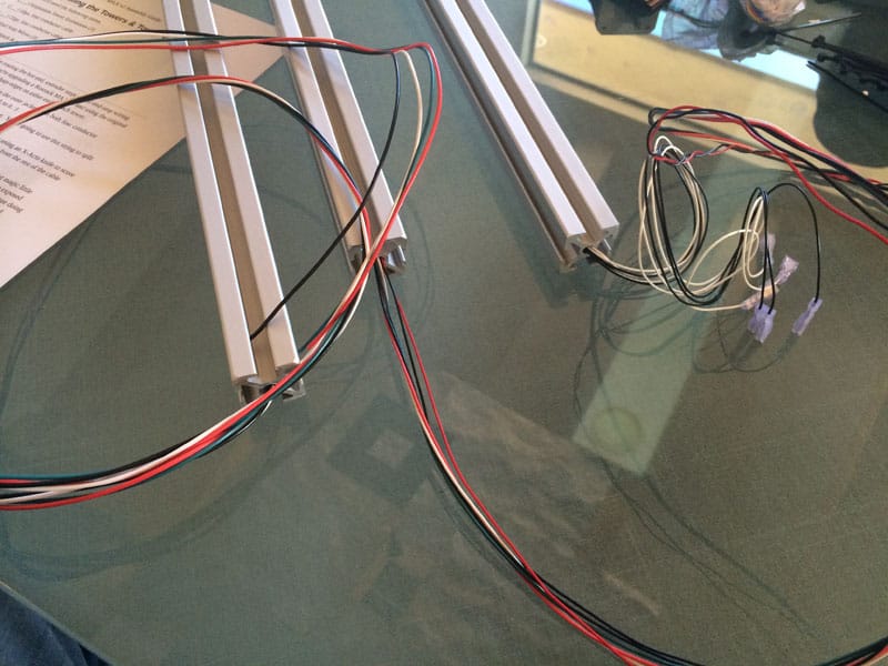
Getting the wiring bundles through the center of each rail is easier said than done…
This was painful to do because you’re pushing a rope. Trying to feed the smaller gauge wires through the hole just didn’t work. Once enough resistance was encountered, they would simply coil up in the hole without going any further down the (very long) length of the rail. There are two tips I can offer. First, if you can, pull the wires through with a coat hanger or other wire. Pushing them is an exercise in frustration. Second, try to twist the wires so that the smallest gauge wire is inside the larger gauge wire and doesn’t touch the walls of the passage.
Having routed the wiring through the rails, it was time to assemble the “Cheapskate Carriages”:
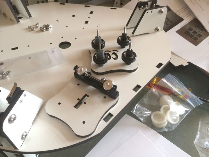
Cheapskate Carriages use 4 ball bearings to ride on the T-Slot rails…
The carriages are very simple. They use 4 ball bearings to ride on the T-Slot rails. If you look closely you’ll see the bearings have “tires” and there is a black axle and a gray axle on the bearings. The gray axles are eccentric so you can adjust tension with a wrench. The tires are set up to mesh with the slot on the rail just right. They seem very stable and precise once assembled on a rail. If I worry about anything it would be how well they hold their tensioning (something I worry about for the belts too!). Time will tell.
While I am on this photo, you can see the limit switches on two of the axes. The instructions have you bend the pins so they’re at right angles. That’s a mistake as there is not enough clearance for the spade connectors they provide from the wiring to push them onto the limit switch pins. If they’d been left alone, it would’ve worked much better. After break one spade trying to make it work, I wound up dumping the spades and soldering all these connections.
Here’s what our Rostock looks like by the end of this Sunday afternoon:
Rostock is 4 feet tall!
One thing you start to notice early in the project is that this printer is quite large and has a very large work envelope. If you excuse all the wiring that’s still hanging out, the fit and finish are pretty decent too.
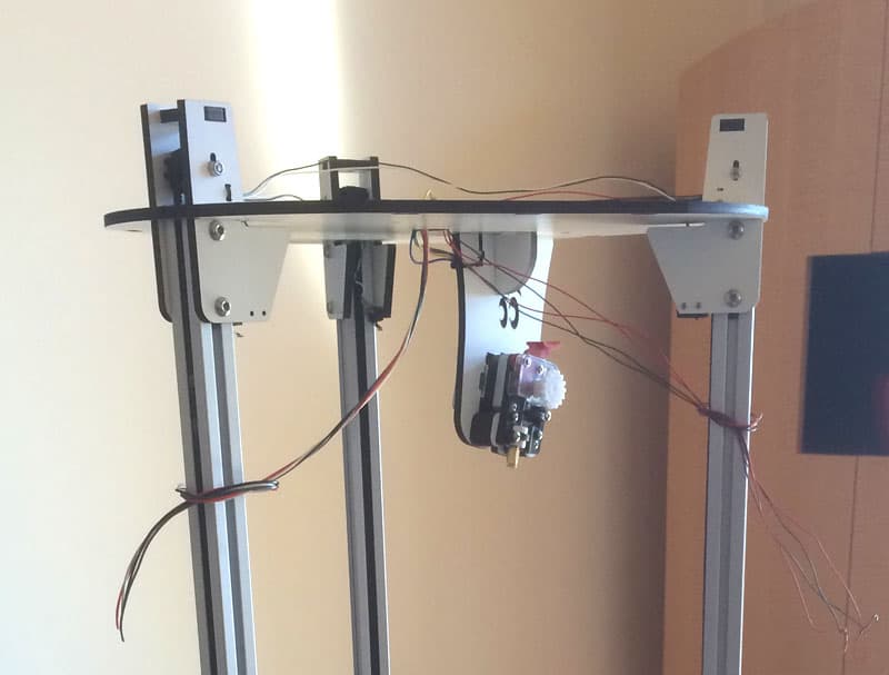
Closeup of the EZStruder…
A stepper motor is used to feed filament down into the hot end so it extrudes out the tip. This is a closeup on the EZStruder which is a neat little assembly that grips the filament so it can be fed via stepper motor.
Next weekend will likely be comprised of a lot of wiring, together with the assembly of the delta arms and the mounting of the hot end. Aside from some very minor frustration with shoving wires through the rails and the limit switches, the kit has been fairly easy. Even the job of routing the drive belts and getting the carriages and belt tension adjusted was pretty straightforward. And the manual has been clear and well written. Hopefully things will continue in that vein all the way through to the end.
Things are really taking shape at this stage!
Part 3
Progress continues on the CNCCookbook Rostock 3D printer. This is our third installment representing our third weekend of progress. Each weekend my brother and I have spent both afternoons for a total of about 6 to 7 hours. Based on that, we’ve now spent probably 20 hours. The printer is mechanically complete and has entered the debugging stage where we test and fix the mistakes we made along the way. So far we’ve only discovered 3 mistakes:
– We had some connectors installed backwards, easily fixed but tedious.
– We had the limit switches connected to the “Min” sockets instead of the “Max” sockets. Very easy to fix but took a moment’s thought to figure out what the problem was.
– We made the wiring harness for the extruder a bit too short. We’ll be grafting on an extension the next time we work on the printer.
Hopefully once the extruder harness has been extended, we’ll be ready to calibrate the printer and actually start making some prints.
This third session consisted largely of wiring:
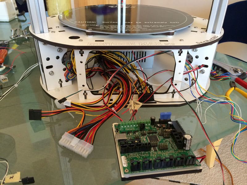
This third and final construction session was largely about wiring…
By and large the kit has been fairly easy to build, the instructions were clear, and there’ve been very few problems. Anyone with a little experience doing mechanical or electronics projects should be able to tackle a Rostock successfully. The proof is in the pudding, and we’ve not yet printed any pudding (if you’ll pardon the expression), but it was gratifying to see the controller was fine, accepted its firmware, and once we got our minor problems sorted, we were able to home the machine. Unless you’re very proficient with these sorts of projects, I would budget a solid 8 afternoon’s worth of time. SeeMeCNC, the makers of the Rostock kit, suggest a build time of 20 hours. Allocate 30 just to be on the safe side and I think you’ll have a good understanding of what’s required. We used very few special tools, at least tools that are outside the realm of basic electronics (soldering iron, needle nose pliers, wire strippers, etc.) or basic mechanical assembly (screw drivers and wrenches). The one thing we did find useful to purchase was a crimper for the very small connectors used in the cabling. In fairness, the Rostock’s instruction manual points out that you’ll need a crimper.
Here’s the Rostock overall to give a sense of its size:
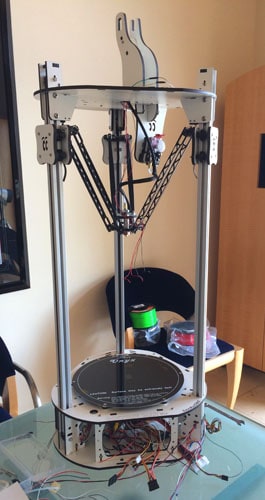
The Rostock stands a good 4 feet tall…
This is no small printer and the work envelope seems huge. I have it happily sitting next to my PC where I think it will live permanently. Once all the acrylic covers and such are in place, it’s a very professional looking unit that would not look out of place at all in a home office or workshop. I suspect the amount of dust and debris downstairs in my machine shop would not be an especially happy thing for it, so I will keep it up here.
The Repetier Software that’s included to manage the printer from your PC seems reasonably simple to operate. I’ll learn more about it as I go, but for now I’ve been playing with slicing various 3D models and preparing g-code that I can look at in GW Editor. I need to tweak a few things to make a RepRap compatible post, but it works pretty well without that even so. I’ve fiddled a bit more with my iPhone case project and also put together another design for a cable minder:
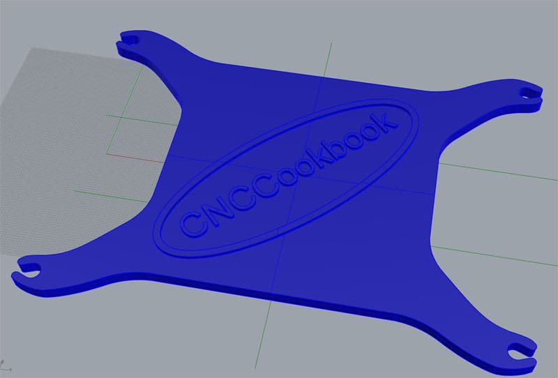
3D Model for a Cable Minder…
The idea behind the Cable Minder is simple: I’m a musician (keyboard/synthesizer player) and there are tons of 1/4″ cables to keep up with. Currently, when not in use, they’re thrown in a box and it’s a real pain to sort them out. With the cable minder, you wind the cable onto it like it’s a reel and snap the two ends into one of the 4 lugs on the corners. This keeps the cables neat and easy to see what you’ve got. Very short cables can go two to a reel as there are 4 snap-in lugs for the ends. We’ll see if it improves my organization, but these kinds of little quickie projects are what 3D printers are perfect for.
Next week we’ll go through (assuming more snags aren’t discovered) calibration and printing our first parts. I’m hoping this coming weekend will be a lot of fun with the Rostock!
Part 4
With one more session of fiddling, the CNCCookbook Rostock MAX v2 was mechanically and electronically complete and it was time for the next stage: calibration followed by printing the first part. We got through the fiddling, calibration, and first part in one long afternoon–about 4 hours.
The calibration took the longest, and we encountered some problems. The main problem was with the “PID Autotune” process. The bed and hot end (extruder) have not only resistive heating but thermistors to measure the temperatures reached. Printing is a bit finicky about temps and wants them to be precise. The PID is sort of the equivalent of a servo for a mechanical CNC axis–it provides feedback that drives the temperature controls. The Rostock’s controller has an “autotune” process for getting the PID dialed in, but we couldn’t get it to work on the hot end. It would zoom the temp up too high and complain things had gotten too hot and then bail out. Eventually I found a reference suggesting I turn down the max PID value from 255 to 128. I did so and Autotune then worked. The claim was it would work properly once the PEEK fan was installed. This was a pain and I wanted to get it back up to 255 from the get go. With a LOT of fooling around, I was able to get it to 210, but no further. Eventually I just kept the PID parameters it had found and did some trials to see how well it could establish and hold temps outside the autotune mode. Things seemed fine, so I cranked it back to 255 and went with it. When I get the PEEK fan installed, I’ll try again.
Note to SeeMeCNC: you need a better Autotune routine that can handle this problem properly. In particular, it should special case the runaway temp problem by dramatically reducing the “P” variable until you get it to quit overshooting. There’s no end of PID tuning information available on the web, and that’s what I resorted to when I was doing my “LOT of fooling around.”
Next up was calibration for bed leveling. This was also a fairly tedious process, although it worked as advertised. What seemed a bit silly was having to adjust the screws the operate the home switches. Geez guys, why weren’t those software offsets that we could change in the EEPROM? It would’ve gone so much faster and saved us constantly forgetting which way to turn the screw to get the desired result. In any event, it got done and judging from the part we made, was done to an acceptable standard.
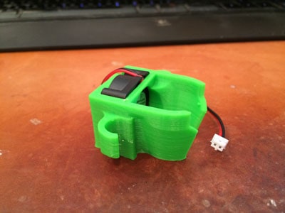
Now we were ready to actually try to make our first part, which is a fan shroud for a PEEK fan on the printer. Here’s a few pix we snapped along the way:
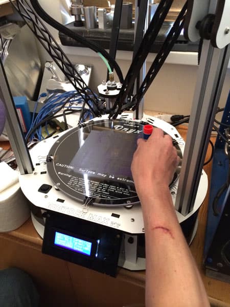
Applying Elmer’s Disappearing Purple Glue to the bed so the print will stick…
For those who read the post about getting things to stick to your 3D Printer’s bed, you may be thinking it’s something of a black art. I think it is for a lot of folks. In addition to all the methods I wrote about in the post, I received correspondents from several people who had more methods to add to the mix. I’m still intent on trying the miracle PEI layer, but that hasn’t arrived yet from Amazon, so I fell back on the Elmer’s Disappearing Purple Glue that the manual suggests. It worked great! Other than the fact that the PEI requires less fooling around and sounds like it releases parts easier (they stick really well to the Elmer’s LOL), I wouldn’t bother switching, but I still intend to go for it. Note that before applying the Elmer’s we swabbed down the glass bed with some isopropyl alcohol to make sure it was clean.
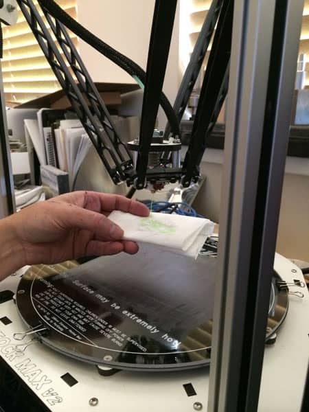
We run 20-30mm of extrusion just to make sure all is well there before starting a print…
I’ve adopted the idea of re-priming the extruder by running 20-30mm of filament through before a run. Just want to make sure things are flowing nicely before we dive in.
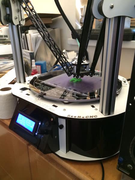
First part chugging away…
That’s about all there is to it. The Repetier software works nicely and before we knew it we had our first part chugging away. The first part is the PEEK Fan Shroud as described in the manual.
Some Observations
The kit was fairly straightforward to build, although you will encounter some minor obstacles along the way. SeeMeCNC probably has room for a v3 that will eliminate those obstacles.
The finished printer seems quite capable. It has a large build envelope and produces very decent quality parts. Here is a view of our first part at 2X magnification:

First part at 2X magnification…
And here it is actual size…
The part came out pretty nicely. Yes, you can see the layer lines, but frankly they’re more obvious in the photos than holding it in the palm of your hand. They wouldn’t be hard to sand away or you can also give them a quick dose of acetone vapors to smooth them away and add some gloss.
So how can we compare this 3D printer to say a CNC Milling Machine?
Different horses for different courses, I’d say.
The surface finish of a good milling job is nicer, but not necessarily hugely nicer. I need to experiment with the acetone vapor trick and see how much it helps. The Mill can work almost any material, while the 3D Printer is limited to just a few filament types. The software side is simpler for the 3D Printer–Slic3r is easier than CAM software, but it isn’t hugely simpler, especially if you use a CAM package like MeshCAM that’s designed from the start to make it easier. I suspect the material costs for 3D Printing filament are higher than for plastics to be milled, but that’s offset by the need for little or no tooling and no cutters. The 3D Printer is likely going to be cheaper, at least until you hit some very serious volumes.
Speed is an interesting question. It seems to take forever to print a part. The one above was well over an hour. OTOH, if you look at the complex 3D surface, it isn’t clear to me a milling machine would get it done a lot faster, at least not a hobby class mill. OTOH, most of what we make on mills is 2 1/2D and that goes tremendously faster.
In the end, I want both kinds of machines and I’m very happy to have the Rostock. It’s plugging away almost next to me making a second fan shroud (different). It’s pretty quiet and while someone warned that ABS is smelly, I can barely detect the smell. This thing is pretty well housebroken and might even be the only option for an apartment dweller.
I’ll be excited to see the ongoing evolution of 3D printers, as well as to continue exploring the capabilities of the Rostock. I’m happy to answer any questions you may have about it in the comments below.
Be the first to know about updates at CNC Cookbook
Join our newsletter to get updates on what's next at CNC Cookbook.