Having a good grasp of thread terminology is important for any CNC'er or Machinist. Threads are an important part of our work, and so it just goes with the territory. Fortunately, there aren't that many terms and they're not hard to understand.
This is your easy guide to screw thread terminology.
Thread Standards and Families
The exact specifications for any thread are determined by Thread Standards. The point of having these standards is interchangeability. You want to be able to purchase off-the-shelf fasteners for particular threads, or be sure that when two parts meant to thread together are made by two manufacturers that they will indeed fit.
There are a number of Thread Standards out there, and being familiar with the names of the common ones is all part of thread terminology. Here are just a few that our G-Wizard Thread Calculator supports:
Thread Families Supported by G-Wizard Thread Calculator
Thread Family
Standard
Sizes
Unified National: UN, UNC, UNF, UNEF, UNS
ANSI/ASME B1.1-2003
371
GW Thread Calculator allows Custom diameter and TPI
ISO Metric M, Coarse and Fine
ASME B1.13-2005
437
GW Thread Calculator allows Custom diameter and TPI
Premium Thread Families added by G-Wizard Thread Calculator
UNM – Miniature Thread Sizes for Watchmaking and similar applications
ASME B1.10
14
UN STI – Screw Thread inserts such as Helicoil. UNC and UNF sizes.
ASME B18.29.1-2010
43
ISO STI – Screw Thread inserts such as Helicoil. Coarse and Fine sizes.
ASME B1.13M-2005
44
Pg (Panzergewinde) Conduit Threads
DIN 40430
10
UNJ – Aerospace Thread. UNJC, UNJF, and UNJEF Sizes
SAE AS8879-D
82 Plus
Custom diameter and TPI combinations
Metric MJ – Aerospace Thread.
B1.21M-1997
157 Plus
Custom diameter and Pitch combinations
British Standard Whitworth (BSW)
British Standard Whitworth (BSW)
19 Plus
Custom diameter and TPI combinations
British Standard Whitworth Fine (BSF)
British Standard Whitworth (BSW)
16 Plus
Custom diameter and TPI combinations
British Association (BA)
BS 98:2008
17

Straight vs Tapered Threads
Two major styles of thread are Straight versus Tapered. Straight Threads are parallel to the Axis. The helix of the thread lies along a cylinder, in other words. With Tapered Threads, the helix lies along the surface of a cone.
Tapered Threads are typically used for pipe and plumbing applications of various kinds where the taper helps ensure a tight seal.
External vs Internal Threads
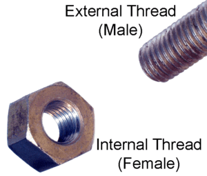
External Threads are screw threads whereas Internal Threads are the threads on the nut that goes on the bolt. They'll have different measurements to provide a looseness that reduces friction and allows for manufacturing errors that are within tolerances.
Handedness
Threads can be right handed or left handed. In other words, the helix can travel clockwise or counter-clockwise.
Most threads are oriented to that the threaded item, let's say a bolt, when seen from the point of the axis atop the bolt, moves away from the viewer when it is turned clockwise. This is known as a right-handed thread.
The opposite direction is a left hand thread.
The usual application for left handed threads involves cases where the rotation of a part would cause a normal right handed thread to loosen rather than tighten. Another example would be a turnbuckle, where threaded fasteners at either end must come together.
One might also use a left handed thread for safety reasons, to prevent a connection with a right handed thread from ever being screwed into the left handed thread.
Form or Threadform
The Form or Threadform thread terminology refers to the geometry or shape of the thread "teeth". Typically, threads are Triangular, Square, or Trapezoidal. The tips may have flats or radiuses as well.
Coarse vs Fine Threads
Many thread families define both Coarse and Fine threads. Coarse threads have a larger pitch or fewer threads per unit of length. Fine threads have a smaller pitch or more threads per unit of length. Think of it as being similar to coarse and fine grits of sandpaper.
Coarse versus Fine is strictly a matter of Pitch and not of quality. Coarse threads are more resistant to stripping because they contain more material. Coarse threads can also be installed faster because they require fewer turns to move a given distance.
On the other hand, Fine threads are stronger because they have a larger stress area for a given diameter. They are less likely to vibrate loose because their helix angle is smaller. In addition, Fine threads allow finer adjustment, and they develop a great Preload with less tightening torque.
Preferred Sizes vs Special or Custom Threads
Thread Families have Preferred Sizes that are defined as part of their standard. These sizes govern diameters, pitches, and sometimes elements of the Threadform.
The Standards often also allow for Sizes that are not mentioned in the Preferred lists. These are Special or Custom Sizes.
Multi Start Threads
Multi-Start Threads have more than one helix that operate in parallel with one another on the same cylinder.
A Single Start thread has just one helix. A Double Start has two helixes that run parallel to each other.
Diameters
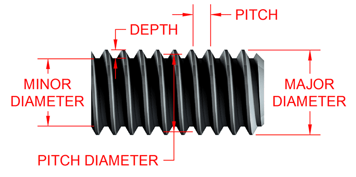
Diameters are a big part of what goes into defining a particular thread.
Nominal Size
This is typically the Major Diameter, or the largest part of the external thread.
Major Diameter
This is the largest diameter for an external thread and the smallest diameter for an internal thread.
Minor Diameter
The Minor Diameter measures the diameter of the "root", which is the innermost part (closest to axis on external, closest to part OD on internal thread) of the thread.
Pitch Diameter (also called Effective Diameter)
The Pitch Diameter is approximately halfway between the Major and Minor Diameters. It's somewhat of an abstract designation because there is no visually obvious feature corresponding to Pitch Diameter, but if the Pitch Diameter of the external and internal threads exactly matches, there will be no play between the two. Hence it is an important bit of thread terminology.
The Pitch Diameter is the preferred diameter to measure when inspecting threads, and one of the most common methods of doing this is Measurement Over Wires.
Pitch Surface
The Pitch Surface is the imaginary cylinder whose axis is aligned with the thread's axis and whose diameter is the Pitch Diameter of the thread.
Pitch
Pitch is the point-to-point distance from one thread to the next at the major diameter.
Lead
Lead is closely related to Pitch. In fact, for a single start thread, they are identical.
TPI
Metric threads are typically specified by Pitch. Imperial threads often use the reciprocal, which would be Threads Per Inch or TPI.
Flank, Crest, and Root
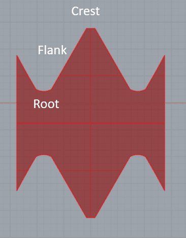
The Crest of the thread is the tip on top. The root is the bottom of the thread. Flanks are the straight sides that connect the crest and the root
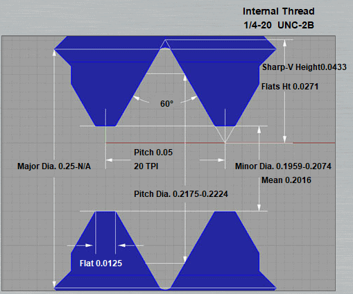
Thread Definition
Each Thread Standard has a particular nomenclature to be used to identify a thread. That nomenclature is called the Thread Definition.
For example, "1/4-20 UNC-2B" refers to a UN Coarse thread, 1/4 inch nominal size, 20 TPI, and with a 2B class of fit.
Length of Engagement
Threads have a recommended Length of Engagement for their idealized behavior. The Length of Engagement is the distance the internal and external threads are engaged with each other.
Classes of Fit or Tolerance Classes
Many Thread Families specify more than one Class of Fit or Tolerance Class. These Classes of Fit tell how precisely the threads must be machined and how tightly they will fit together.
Axis
The Axis is the imaginary centerline the thread helix spirals around.
Thread Depth
Thread Depth is the difference between Minor to Major diameter
Thread Angle
This graphic from G-Wizard Thread Calculator shows a 60 degree thread angle:
Mechanical Advantage
Mechanical Advantage is the amplification of force. Threads create Mechanical Advantage because their teeth operate like wedges. The smaller the Pitch of a thread, the greater the Mechanical Advantage.
Be the first to know about updates at CNC Cookbook
Join our newsletter to get updates on what's next at CNC Cookbook.