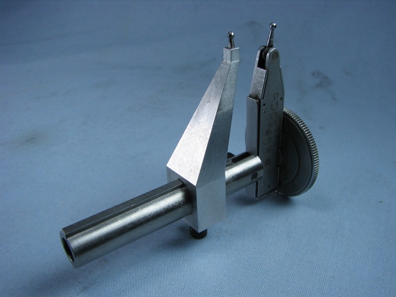
One of the most accurate ways to measure a bore is with a dial bore gage, but these can be really expensive and seldom used tools. A nice Mitutoyo dial bore gage set is almost $400 as I write this.
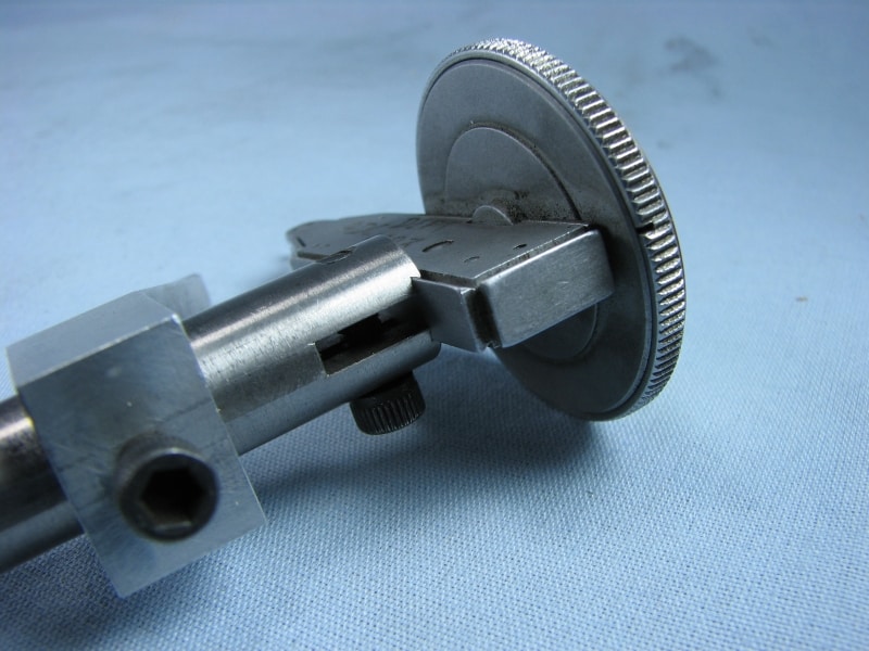
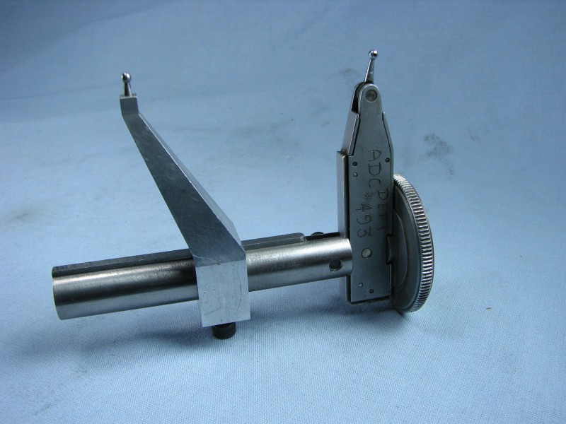
I loved this gadget by gbritnell I saw on HMEM to adapt a DTI to the task:
You didn't provide any text to be rephrased. Please include the text you want rephrased in your request.
Pretty slick!
Snap gages are cheap, but take a lot of "touch" to be accurate. Dial bore gages are one of the best metrology tools for bores, but they're costly. These guys fall somewhere in the middle, but closer to the dial bore gage. They'll need to be calibrated against a reference, but once that's done, they'll be quick and easy to use.
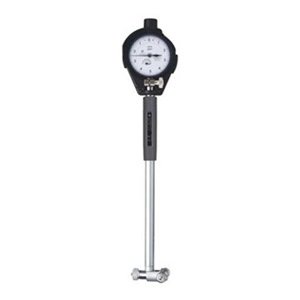
Dial bore gage...
Be the first to know about updates at CNC Cookbook
Join our newsletter to get updates on what's next at CNC Cookbook.