The Design
Here's the concept: I bought a bag of 100 slotted optical switches on eBay for almost nothing. These are normally open, NPN switches. We need a limit switch to behave in a normally closed manner, so it trips if a wire is broken. To achieve this, we block the beam (closing the switch) until the limit is hit, which unblocks the beam and opens the switch. Mach 3 can handle the polarity (normally open or normally closed) needed to trip the limit.
Now picture a little gate that interrupts the beam inside the optical switch. Something like this:
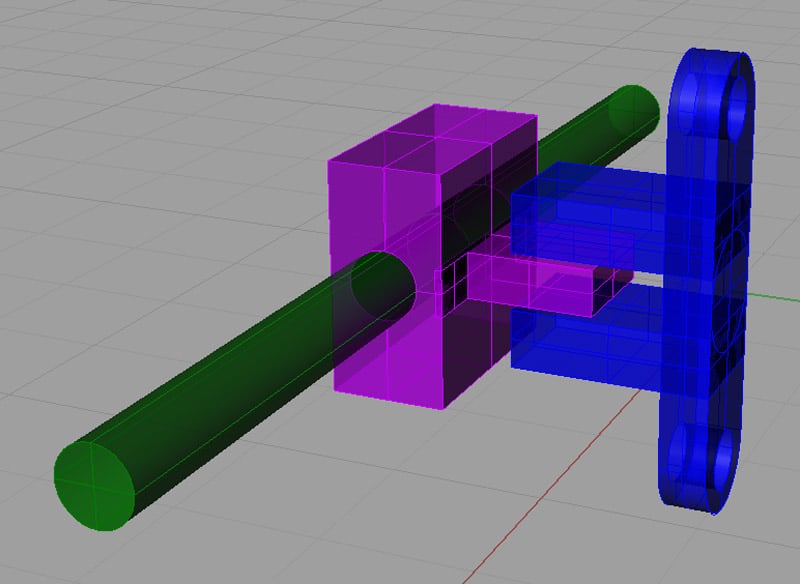
Optical Switch (Blue), Sliding Gate (Purple), Arm (Green)...
The arm has a spring on either side to center it and goes through a hole on either side of the lid:
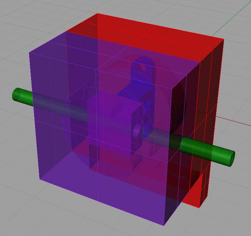
The assembled limit switch. Note plungers on either side-it works 2 ways...
The switch is mounted rigidly via the holes at the bottom. A bracket is placed on the moving part of the machine that will press against the plunger, open the gate, and enable the beam when the limit is hit:
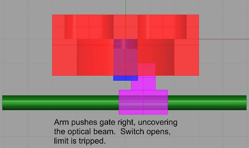
The limit is tripped when the gate uncovers the optical beam...
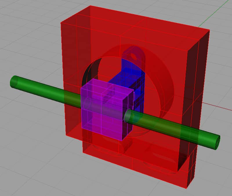
With the lid removed. Do I want to make the base taller and go with a thin lid? I chose this design because my switch (the blue thing) stands up pretty tall and I was looking to machine the top and bottom out of something readily available and easily machined-in this case 5/8" aluminum.

Dimensioned Drawings
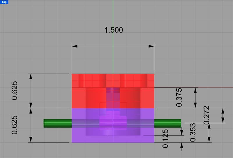
Top View...
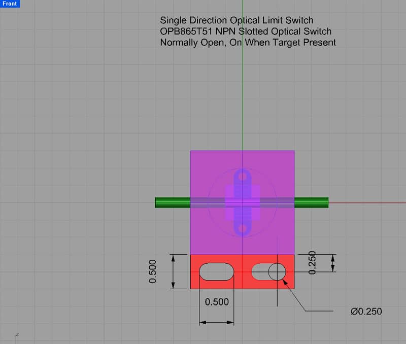
Front View...
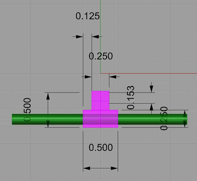
Gate Detail, Top View...
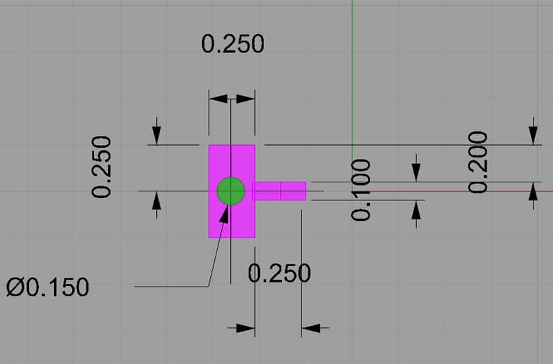
Gate Detail, Right View...
Machining Steps
Machining would appear to be simple:
Bottom
1. Start with a piece of 5/8" thick aluminum plate. Square it with a flycutter on all sides.
2. Mill down the bottom side of the lid until it is 0.25" thick and cut the slots for the mounting bolts. Probably chain drill those slots with a 1/4" drill bit and then take a smaller mill to smooth out the edges. One could also use a slitting saw to cut the large amount of stock to be removed over the mounting bracket and then clean it up with a light milling pass.
3. Bore the cavity that the optical switch sits in.
4. Drill and tap the optical switch mounting holes.
5. Drill a hole underneath the optical switch for the leads, and drill a connecting hole from the bottom for the wiring to come in and out.
6. Drill and tap the holes for the bolts that hold the lid in place.
Top
1. Start with a piece of 5/8" aluminum plate. Square it with a flycutter on all sides.
2. Bore the center cavity.
3. Drill the side holes that the push arm will ride in.
4. Drill and countersink the holes for the bolts that hold the lid in place.
Gate
1. Start with a piece of 1/4" thick aluminum plate.
2. Bore the hole for the arm.
3. Mill the edges to make the thin gate.
4. Drill and tap the setscrew holes on either side of the gate.
Arm
1. Start with a piece of pre-finished steel rod, cut to length. Round or chamfer the ends as desired.
Wiring
The optical switch takes 4 leads, so I'm planning to use CAT5 cable. It's the same stuff you use to make LAN connections. You can buy already made up CAT5 cables in various lengths. Just cut one connector off, strip the wires, and solder to the optical switch. Use a little heat shrink tubing to ensure there are no shorts among the leads.
For the lathe, I want 2 limit switches and 2 circuits. We will use 1 circuit for each axis-X and Z. X is left (-) and right (+), Z is in(-) and out (+). So, we want to set the machine home positions to be the extreme positive for both axes-far right and far out (cool!). I will be mounting the optical limit switches on the apron and mounting stop blocks on the lathe bed (X left and X right) and on the cross slide (Z in and Z out). This way we will only use 2 inputs from the GRex for the Home/Limit system. The machine knows whether to view a stop as a Home or Limit based on whether it was commanded to home or not, as well as based on what direction it was travelling when it hit a stop and on which circuit (axis) it got the stop signal.
Be the first to know about updates at CNC Cookbook
Join our newsletter to get updates on what's next at CNC Cookbook.