CutViewer CNC Simulator
With G-Wizard Editor no longer being available for purchase, we are now recommending the CutViewer CNC Simulator as a great alternative for simulating and verifying g-code programs. CutViewer is a powerful and user-friendly CNC simulation software that allows you to visualize your g-code in a 3D environment, helping you to identify potential issues before running your program on the machine.
Benefits over G-Wizard Editor include:
- Browser based, so you do not need to download anything to use it.
- Free to use, with no limitations on the number of simulations.
- Runs on any device with a web browser, including tablets and smartphones.
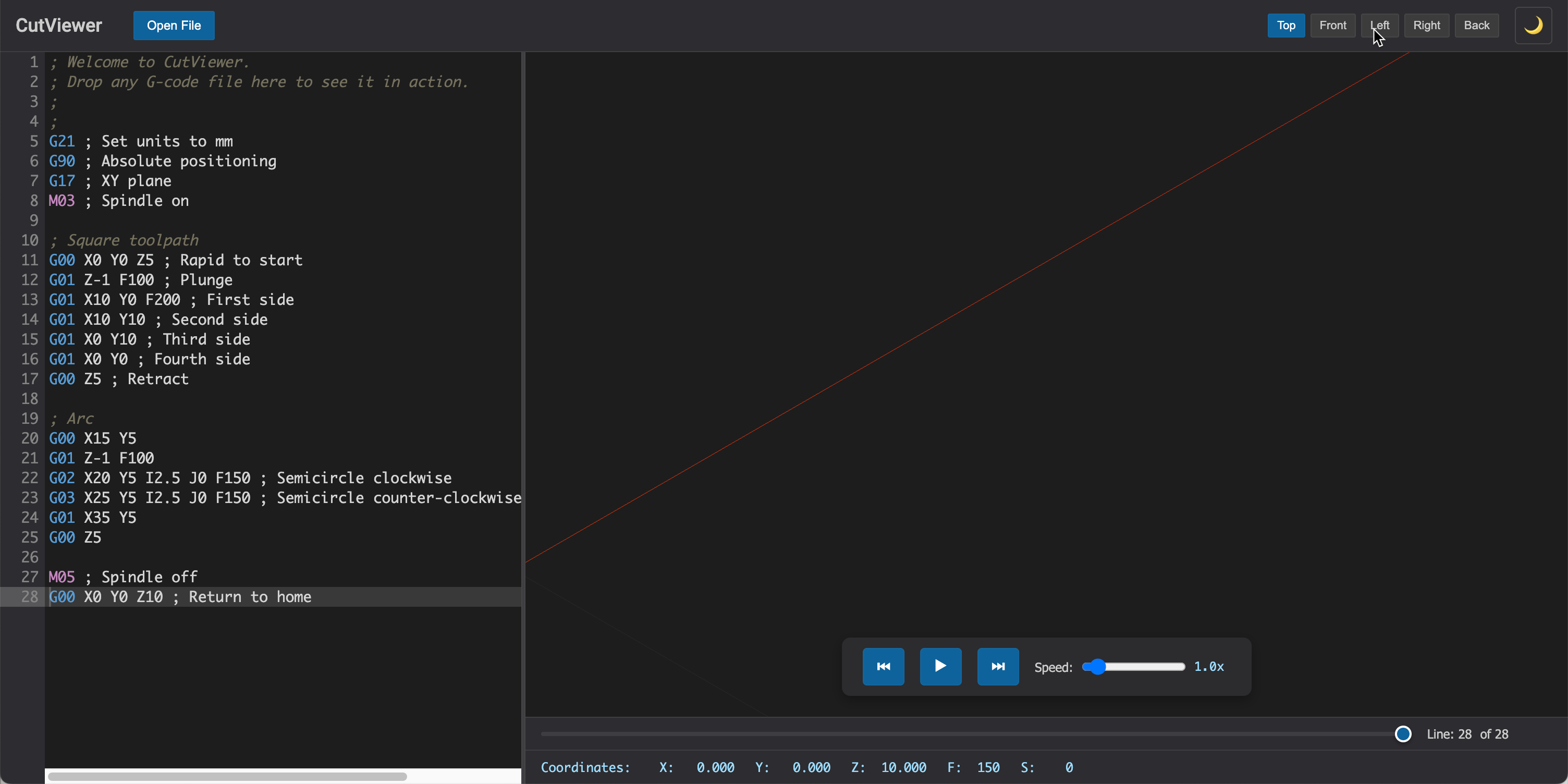
You can access the CutViewer CNC Simulator at https://cutviewer.com/. Simply upload your g-code file, and you can start simulating your CNC programs right away. The intuitive interface allows you to easily navigate through your g-code and visualize the toolpath in 3D, making it easier to spot any potential issues before they occur on the machine.