A CMM is a device used to take accurate measurements from physical objects–typically parts in your machine shop. The letters “CMM” stand for “Coordinate Measuring Machine.” They’re extremely useful to have around, so much so that many shops experience productivity boosts when they locate a CMM right on the shop floor where it can be easily accessed during the course of normal operations. For CNC’ers, having an accurate probe and the software to make it sing also enables many CMM-like measurements to be taken right on the machine. The operative buzzword is “in-process probing.”
A CMM is not unlike a CNC mill with a probe in many ways. Here’s a typical example:
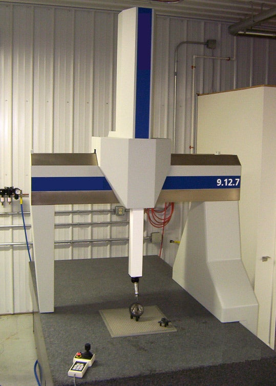
A typical Coordinate Measuring Machine. Source: “9.12.17 Coordinate measuring machine” by Vulture19
As you can see, it has 3 axes in a gantry style arrangement, the table is a granite surface plate, and there’s an electronic probe instead of a spindle.
But none of this is cheap. CMM’s are very expensive–used ones go for close to $20,000 on eBay and new ones are more. Highly accurate probes are also not cheap. But if you have a mill with an accurate DRO, you can do some surprisingly good CMM-type work with it. This is probably not something a production shop wants to do much of–it is time consuming enough that it’ll be cheaper to buy a real CMM–but for amateurs, small shops, and in a pinch it can be a helpful tip.
Consider the task of accurately finding the location of a boss on a part. You might set that up on the mill as follows:
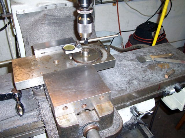
The part with the boss is positioned in the vise and an indicator holder is in place to help find the exact center of the boss…
Use your handwheels to position the part until the indicator can rotate around the boss without a twitch–now you’ve located the center of the boss. Zero the DRO and use an edgefinder to find the distance to the center of the boss from any edge of the part:
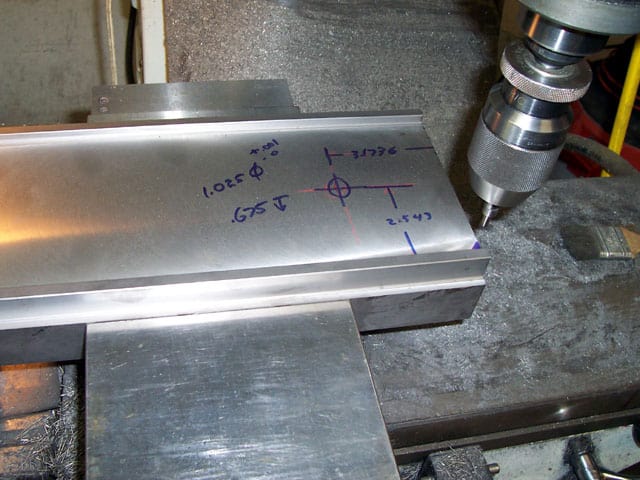
We’ve now marked up the workpiece with the dimensions measured on our makeshift “CMM”
Of course if you have a CNC, you can easily do this too, but you can also see how a probe would make it all very quick and easy to do. In a pinch, you might find it is quick enough to use that old Bridgeport off in the corner to pick up a few measurements while all the machines and the shop’s CMM are in use.
BTW, this idea came to me from the Widgitmaster who was using it to adapt a turret to his manual lathe.
Like what you read on CNCCookbook?
Join 100,000+ CNC'ers! Get our latest blog posts delivered straight to your email inbox once a week for free. Plus, we’ll give you access to some great CNC reference materials including:
- Our Big List of over 200 CNC Tips and Techniques
- Our Free GCode Programming Basics Course
- And more!
Just enter your name and email address below:
100% Privacy: We will never Spam you!

Bob is responsible for the development and implementation of the popular G-Wizard CNC Software. Bob is also the founder of CNCCookbook, the largest CNC-related blog on the Internet.
I do that all the time! Great idea for sure.
I do something similar with a cheap USB microscope. I got one for $20 from ebay and made a mount to hold it below the spindle on a Bridgeport. I draw a cross hair on a piece of clear plastic, even a plastic bag will work, and then tape that to my laptop screen. Then I focus on the part (quill for rough and knee for fine focus), and write down x-y co-ordinates of various features. With this you can do things you cannot do with calipers.
For example, one time I needed to reverse engineer a Canon DSLR camera mount. So I rested the camera on the vise, face up without the lens. Then with my cheap setup I found the left side, right side, top and bottom of the lens with the cross hair line and split the differences to set 0,0 above the center of the lens. Then I moved over to flange locations and the electrical contact pin locations and wrote down all of the co-ordinates. I put these in SolidWorks and used these dimensions to make an aftermarket lens mount adaptor for non-Canon lenses.
The beauty of this technique is that the quality of your USB microscope lens does not matter. Used this way, a ten thousand dollar microscope would be no better than the $20 one. The cheap plastic lenses could have awful pincushion and distortions like a fun house hall of mirrors and it would not matter, because the cross hair is always over the same part of the lens. For me this trick worked like a charm. My aftermarket lens mount design worked perfectly on the first try.
What you describe in this article is pretty much SOP here. Even with 2 types of scanning equipment here (2D and 3D laser scan) I still like the reality check of throwing something up on the mill and performing some contact metrology. The Haimer 3D sensors are great for this type of work.
a mill with a readout or a cnc with encoder feedback is in no way a CMM. if your machine is inaccurate so will be your parts. ballscrews can wear out, glass scales and encoders can skip. There is no substitute for a CMM in a temperature controlled lab.
So Craig, you never use a set of calipers because they’re not nearly as accurate as a CMM, right? And you never would use a micrometer either, for the same reason? There’s no point in having a DRO on a machine because it can’t measure as accurately as the CMM as well. And, we always need to make every measurement as accurately as a CMM can make the measurement, right? BTW, why not junk the CMM and go with a laser interferometer? After all, a CMM is no way a substitute for the kind of accuracy one of those can produce.
Clearly my tongue is well inside my cheek when I ask those questions. Of course there’s value in being able to make the kinds of measurements I suggest here, and we have many commenting in agreement. Any machinist needs to understand what tolerances are required and how NOT to spend too much time worrying about tolerances beyond that. To do otherwise will just needlessly drive up your costs.
I was studying the Controller software and manual for the Planet CNC system. There is a software correction if the camera bore sight is not exactly parallel to the Z axis. Of course this will create shadow areas shooting at an angle at various depths. Another little geometry problem to calculate the shadow.
Quite a well thought out system.
Measure it with Micrometers,
Mark it with chalk,
Cut it with an axe.
Understanding fits and precision is key to the basic economics of machining.
…. and cutting firewood..
I had to draw up the profile of a conga years ago.
Just made two cones and mounted them on the mill with the conga in between.
Used a long drop indicator, (ball tip) set at zero on the lowest point, and took a reading every 0.6 inches. 32 inches later I had my profile.